Tullygrainey
-
Posts
1,139 -
Joined
-
Last visited
-
Days Won
60
Content Type
Profiles
Forums
Events
Gallery
Blogs
Everything posted by Tullygrainey
-

Alan's grubby little shunters thread
Tullygrainey replied to Tullygrainey's topic in British Outline Modelling
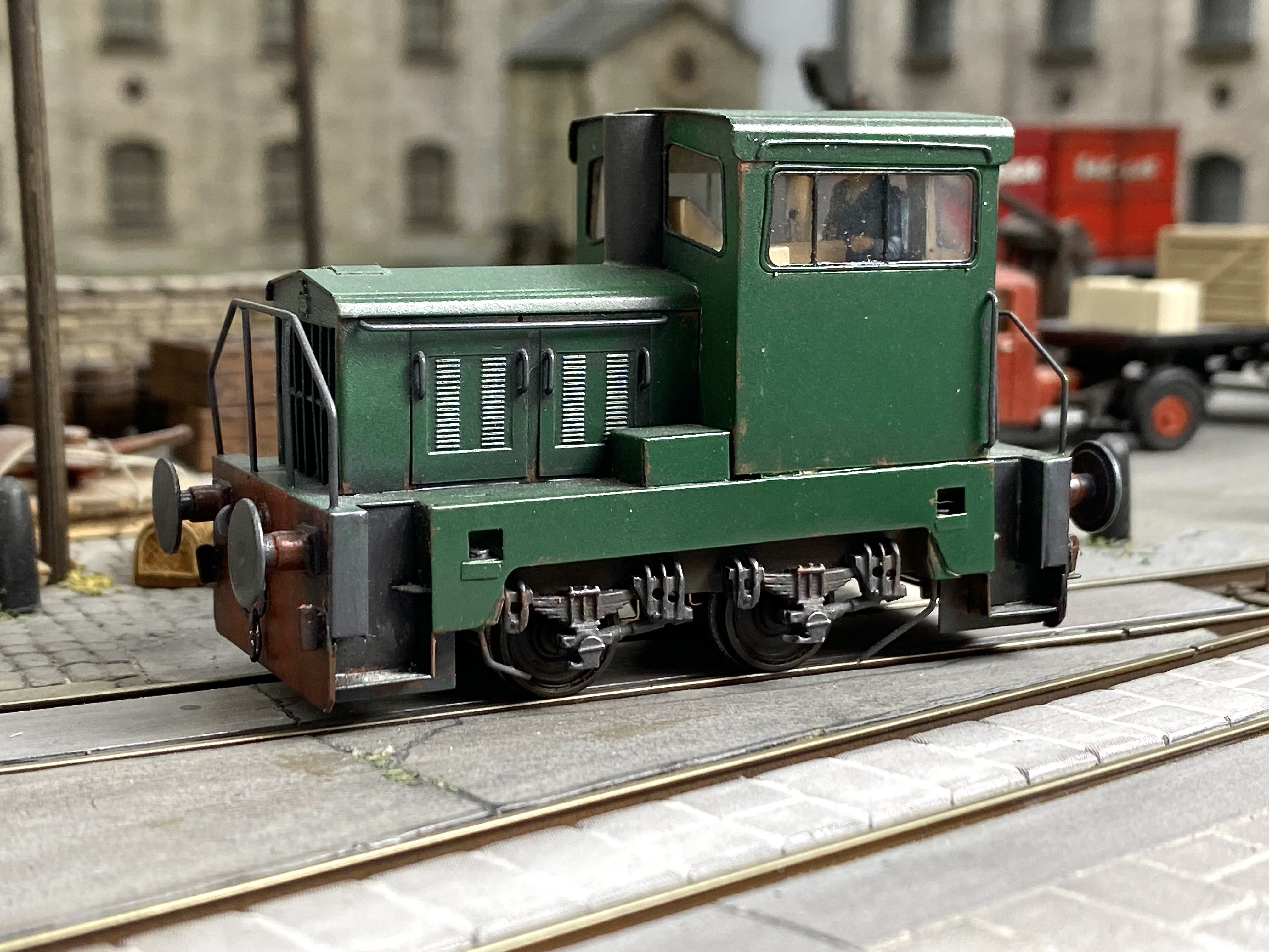
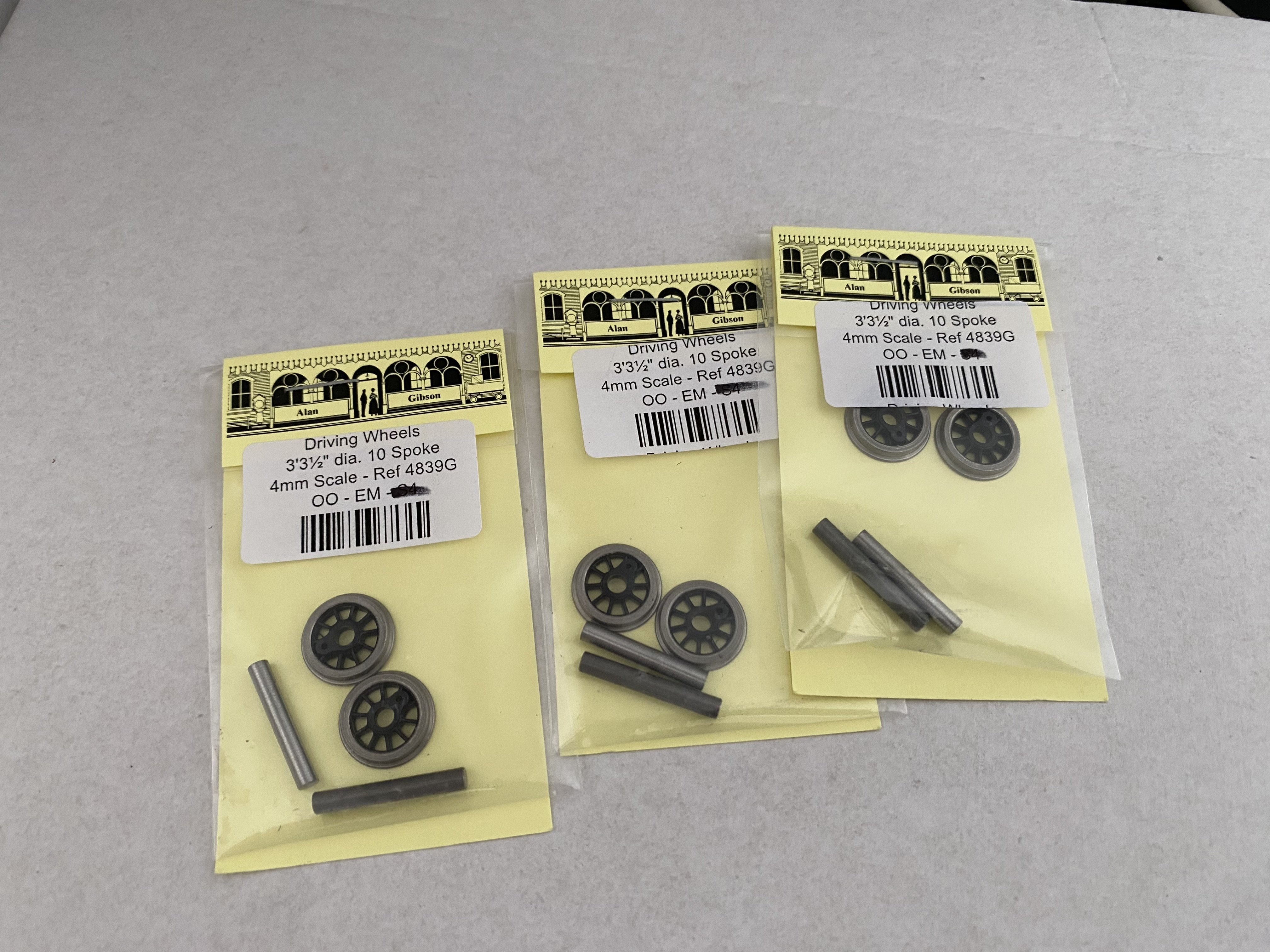
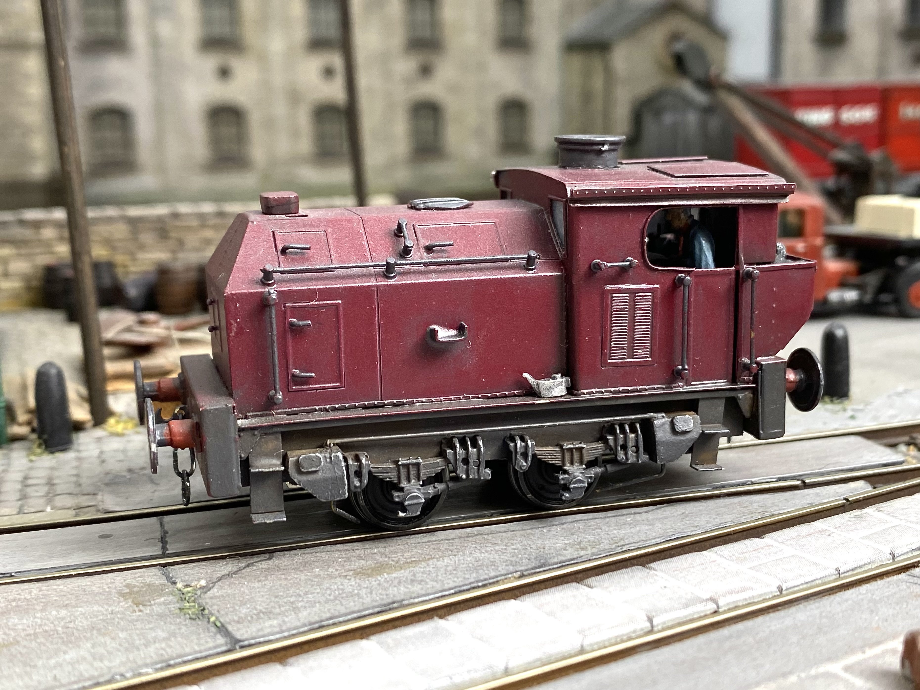
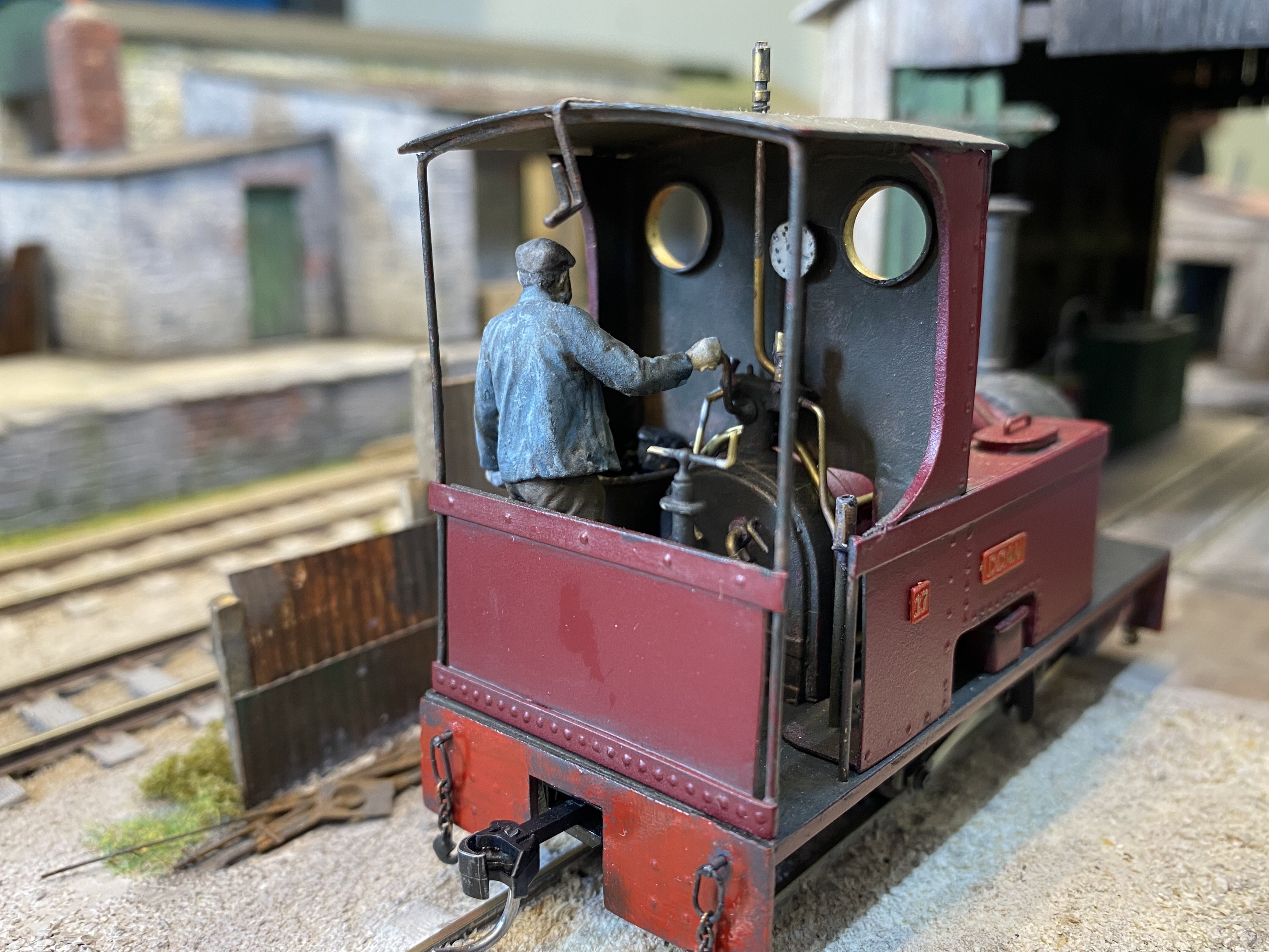
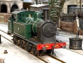
Gibson wheels have arrived. The Hunslett is a pretty diminutive loco and the boiler diameter is only 16mm in model form. The High Level coreless motor I was intending to use fits inside ok but would require hacking lumps out of the bottom of the boiler at the back to get it in there when mounted in the chassis. To minimise the amount of surgery needed (I hope), I've ordered a smaller motor. So job parked for now. Here are a couple of the locos already on the grubby shunter roster - a Sentinel 0-4-0 Vertical Boiler steam engine and a Thomas Hill rebuild of the Sentinel into a Vanguard 0-4-0 diesel. Both built from RT Models kits. High Level 4wd bogies and Mashima motors.
-
Alan's grubby little shunters thread
Tullygrainey replied to Tullygrainey's topic in British Outline Modelling
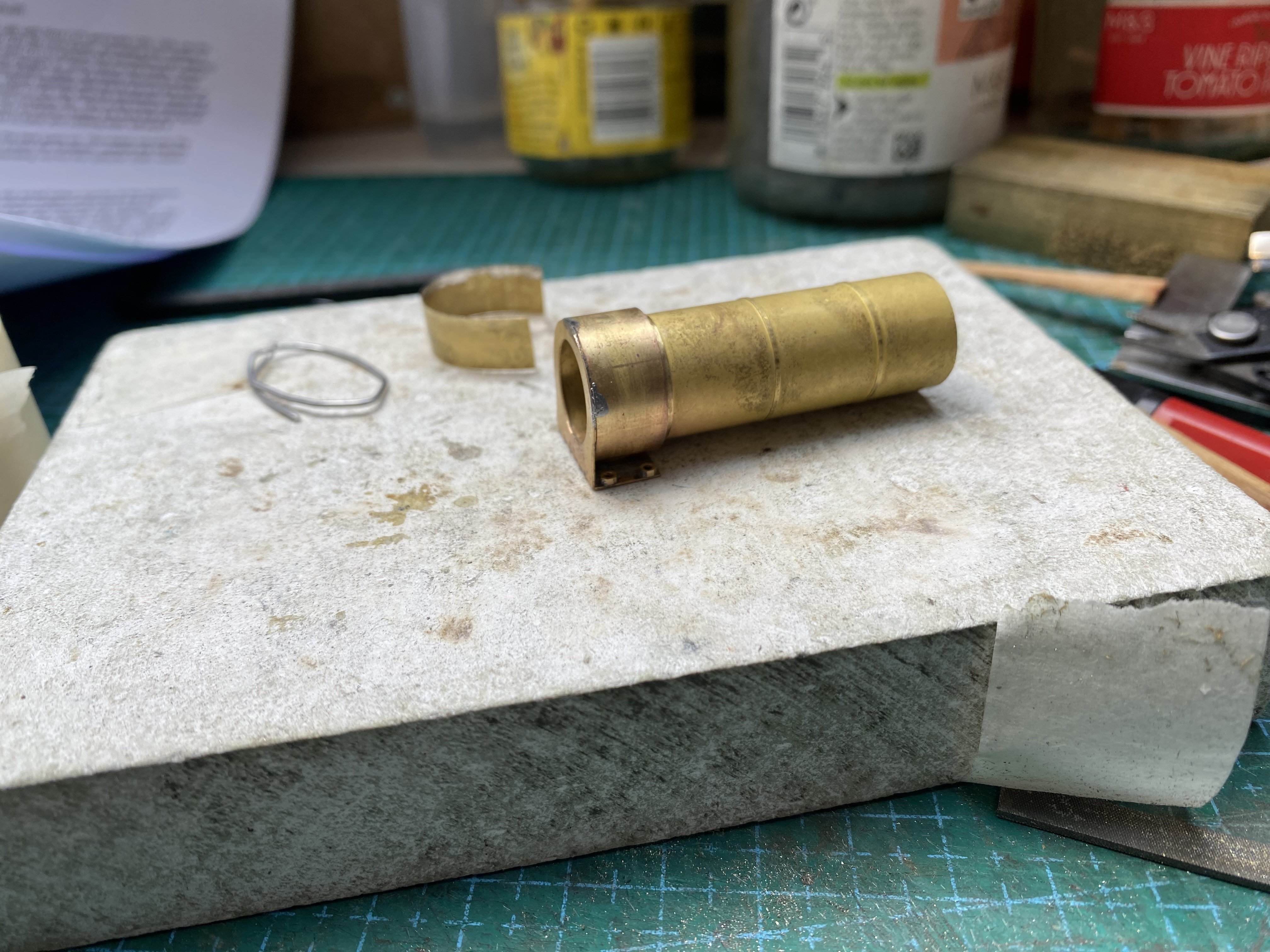
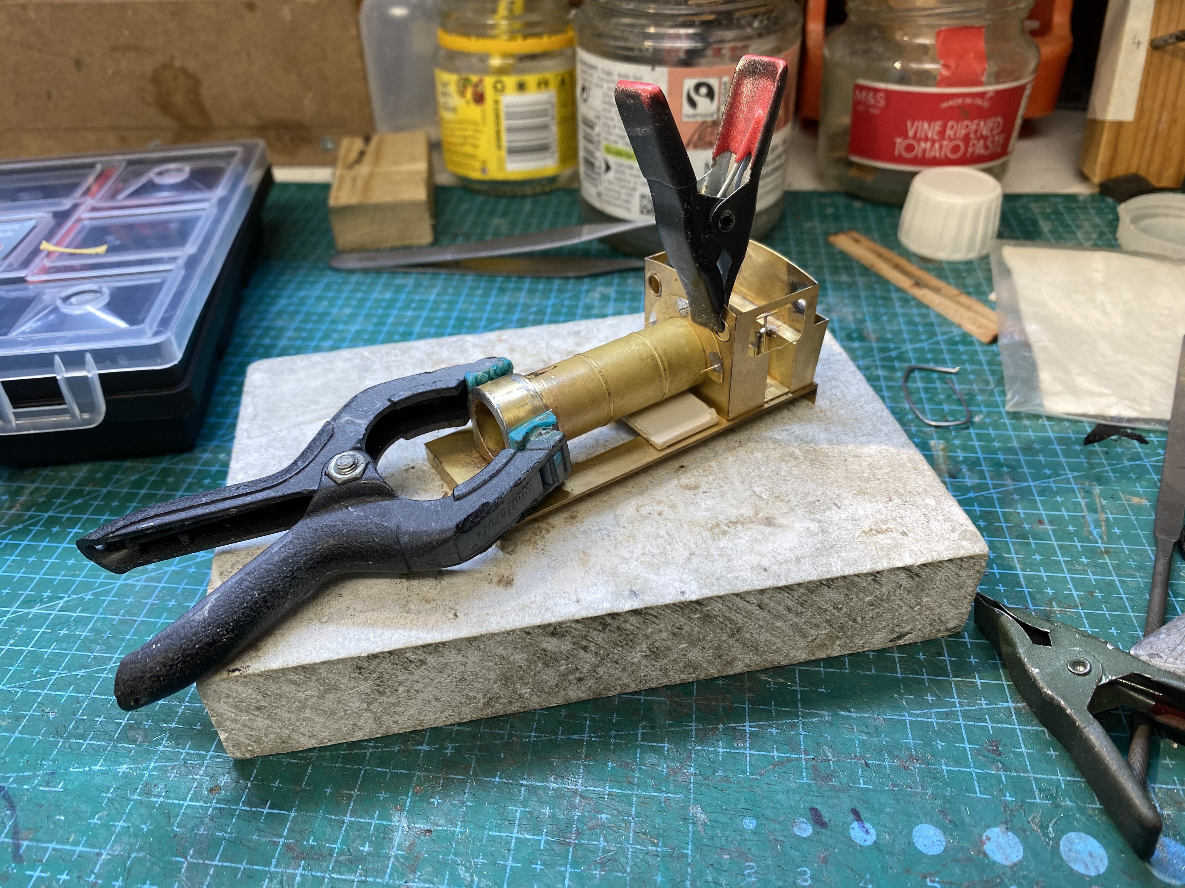
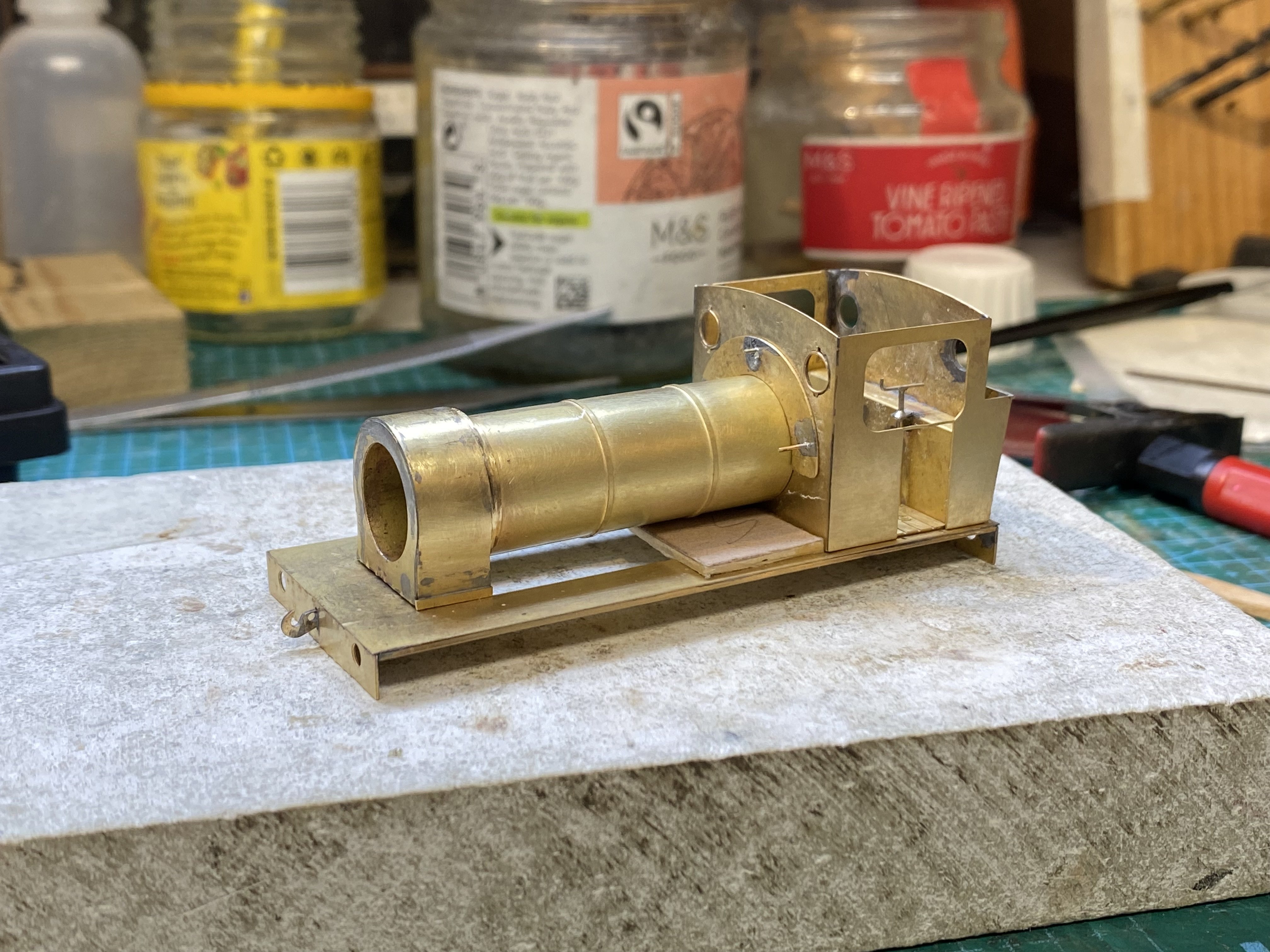
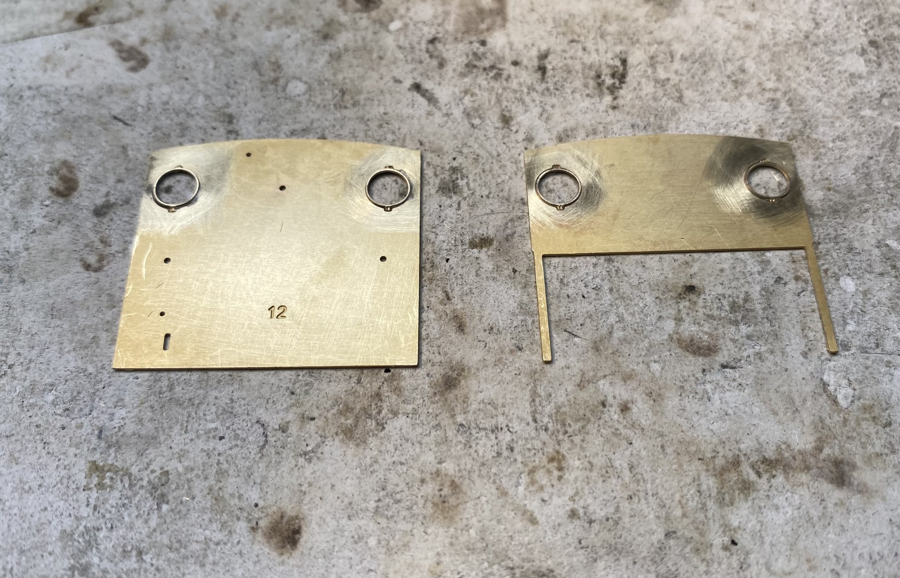
More Hunslett. The cab is well on the way now. Trial fit of the usual High Level gearbox, a RoadRunner + for this one. Gibson wheels on order. Boiler next. Laminating layers for the smokebox is always a challenge - four layers in this case if you count the boiler. Getting enough heat into the thing and keeping it neat and tidy takes time and patience. There's always work for the fibreglass pencil when the soldering is done. Thanks to the smokebox front plate not seated properly and the difficulty of wrapping each layer tightly, the final wrapper came up short. Rather than dismantle the whole thing and start again, I've added small strips either side to bridge the gap. Not ideal but better than a space. The sand boxes will hide this to some extent anyway. I might have another go at it tomorrow.
- 42 replies
-
- 10
-

-
Alan's grubby little shunters thread
Tullygrainey replied to Tullygrainey's topic in British Outline Modelling
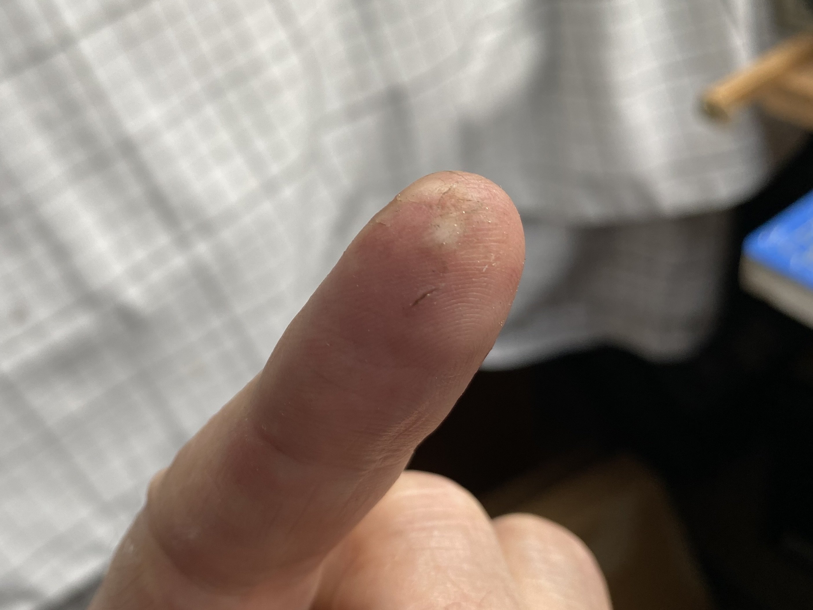
Sometimes when soldering, no clamp does the job better than your fingers. There is a small price to pay for this though
-
John's mainly Industrial EM thread.
Tullygrainey replied to Mayner's topic in British Outline Modelling
Thanks for this John. Very interesting. It's like looking at a little bit of the history of etched kits. I came to kit-building late in the day with the advantage that most of the truly grim stuff had already bitten the dust leaving only the better kits. Some pretty high spec bits in your locos - Sharman wheels, Portescap gearbox/motors and so on. Cutting edge when you built them I'd say. -
Clogherhead - A GNR(I) Seaside Terminus
Tullygrainey replied to Patrick Davey's topic in Irish Model Layouts
Looks at home I think. Hope it performs well for you Patrick. -
Alan's grubby little shunters thread
Tullygrainey replied to Tullygrainey's topic in British Outline Modelling
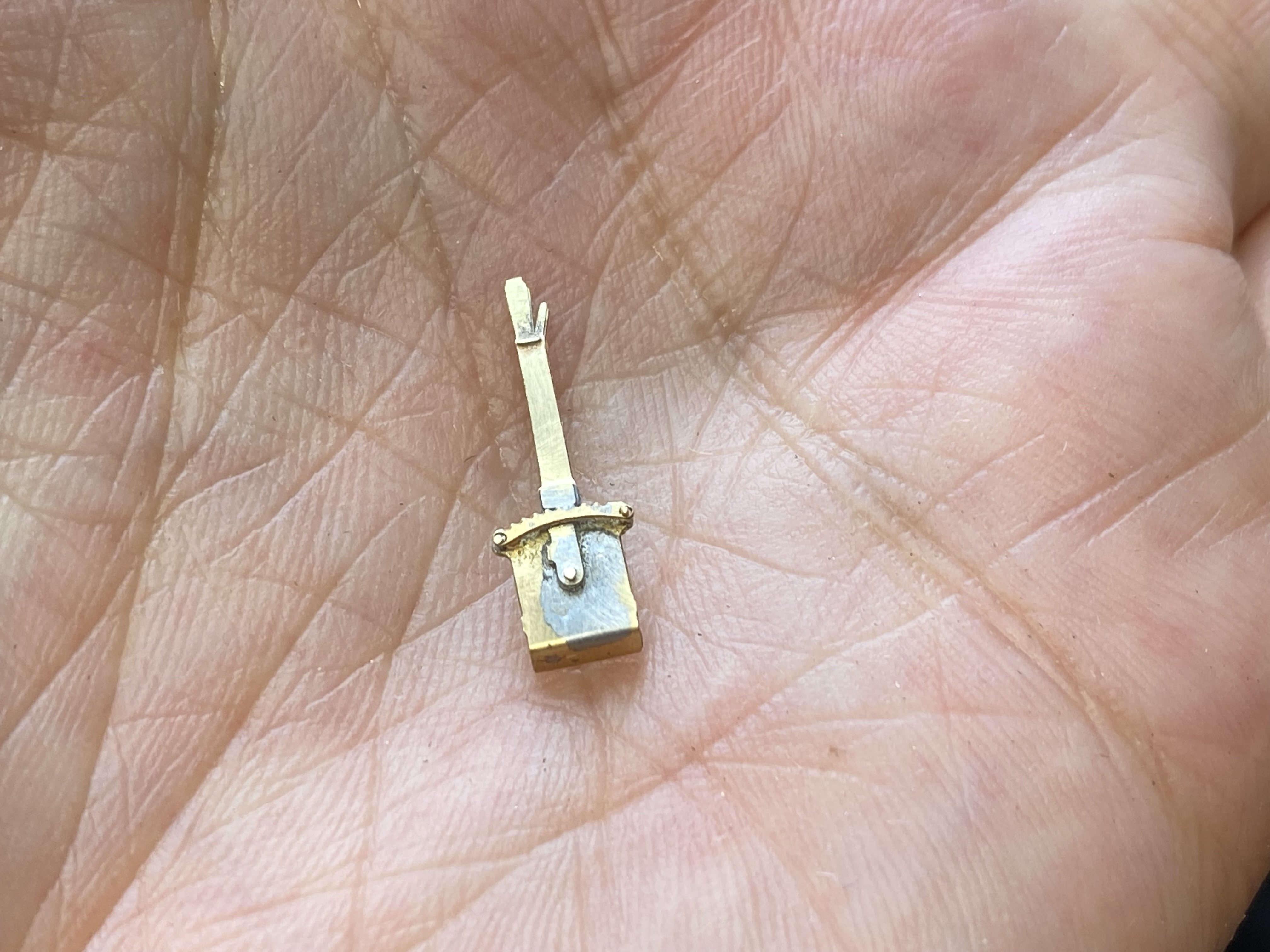
Now I am inordinately proud of this. Four separate bits plus 3 bits of wire. Just a pity it'll be hidden away inside the cab. I'd like to solder it on the cab roof
-
Alan's grubby little shunters thread
Tullygrainey replied to Tullygrainey's topic in British Outline Modelling
I like those John. Tell us a bit about how they were built. If you can remember after 25 years that is -
Alan's grubby little shunters thread
Tullygrainey replied to Tullygrainey's topic in British Outline Modelling
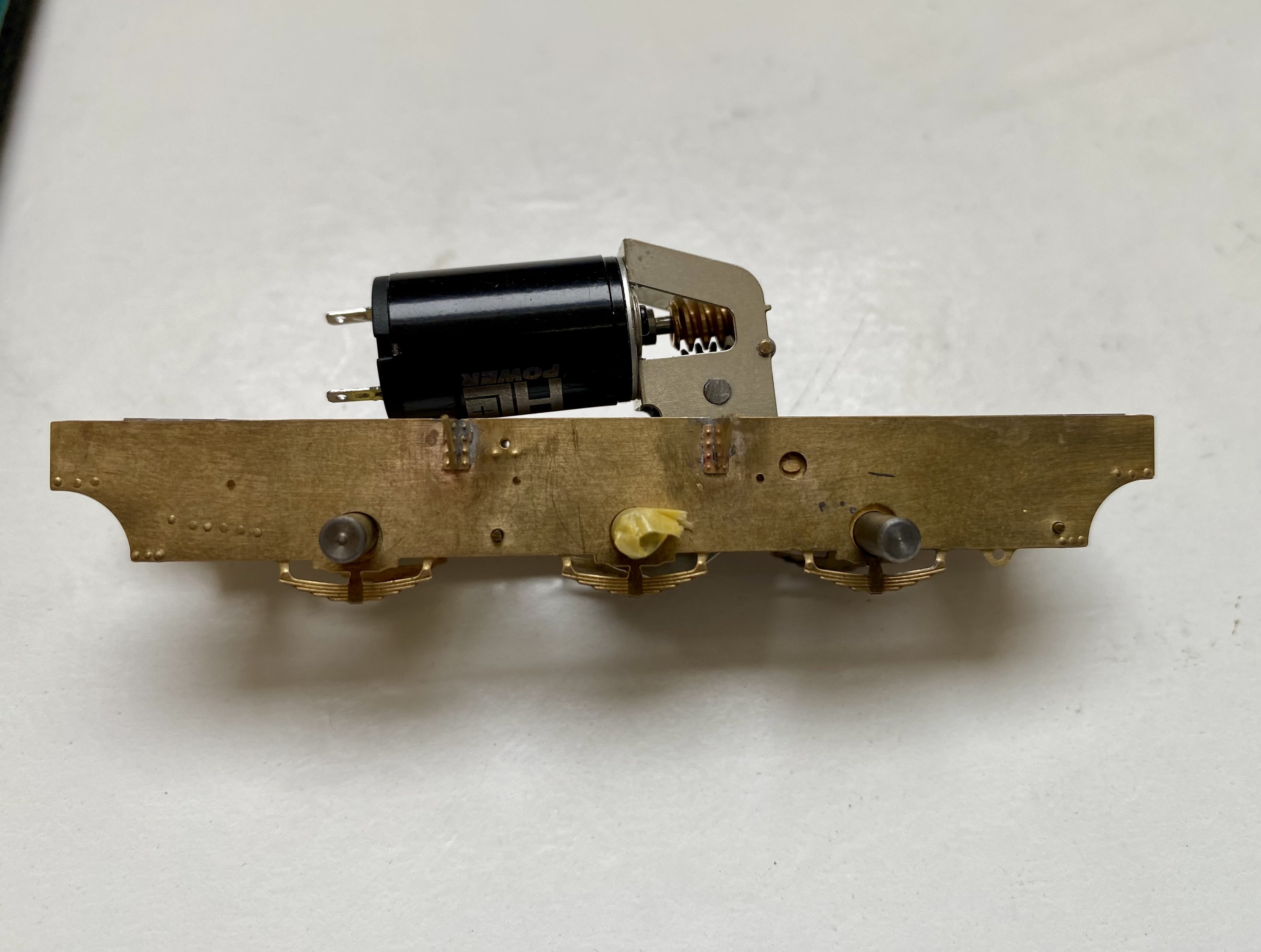
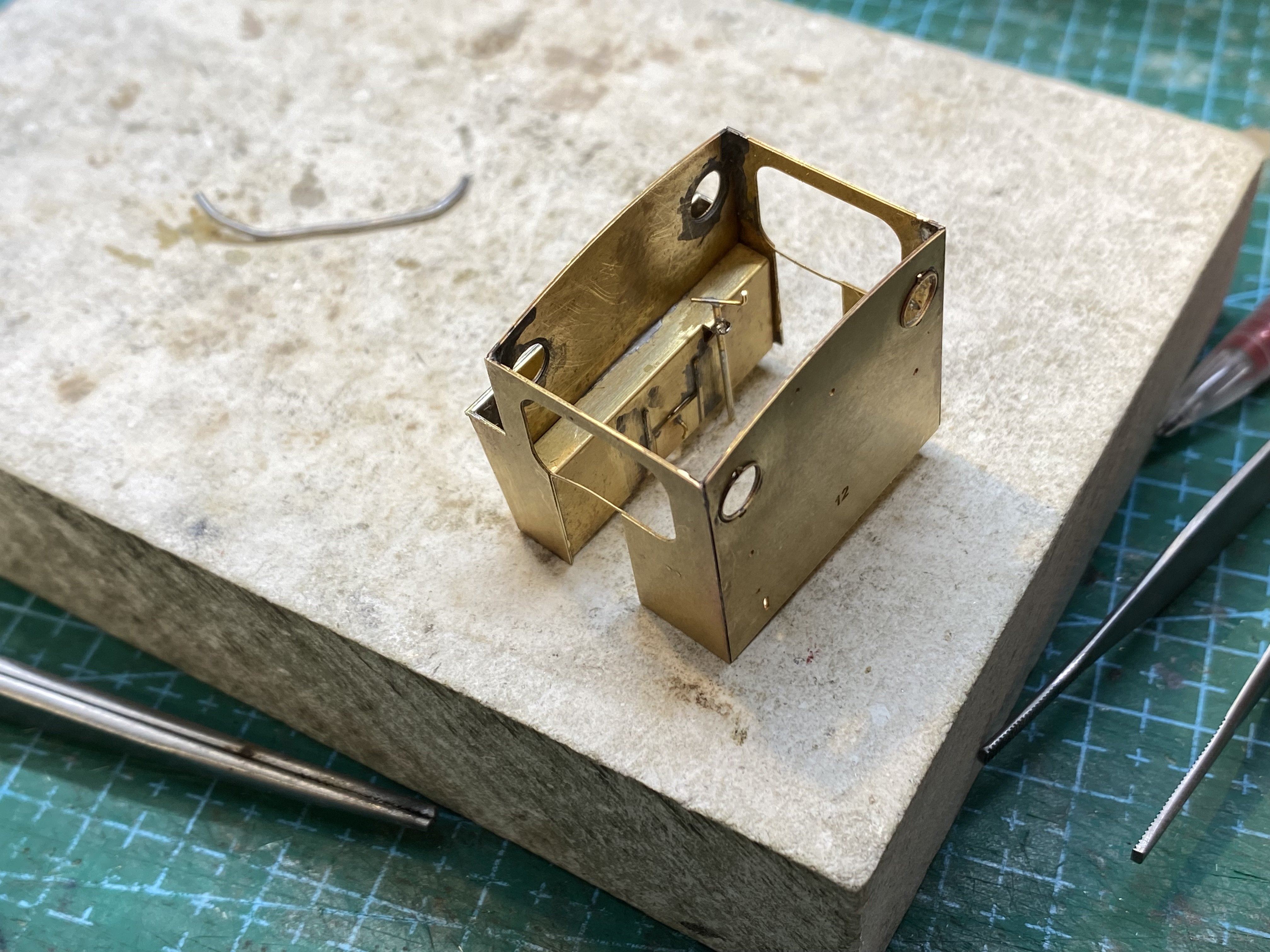
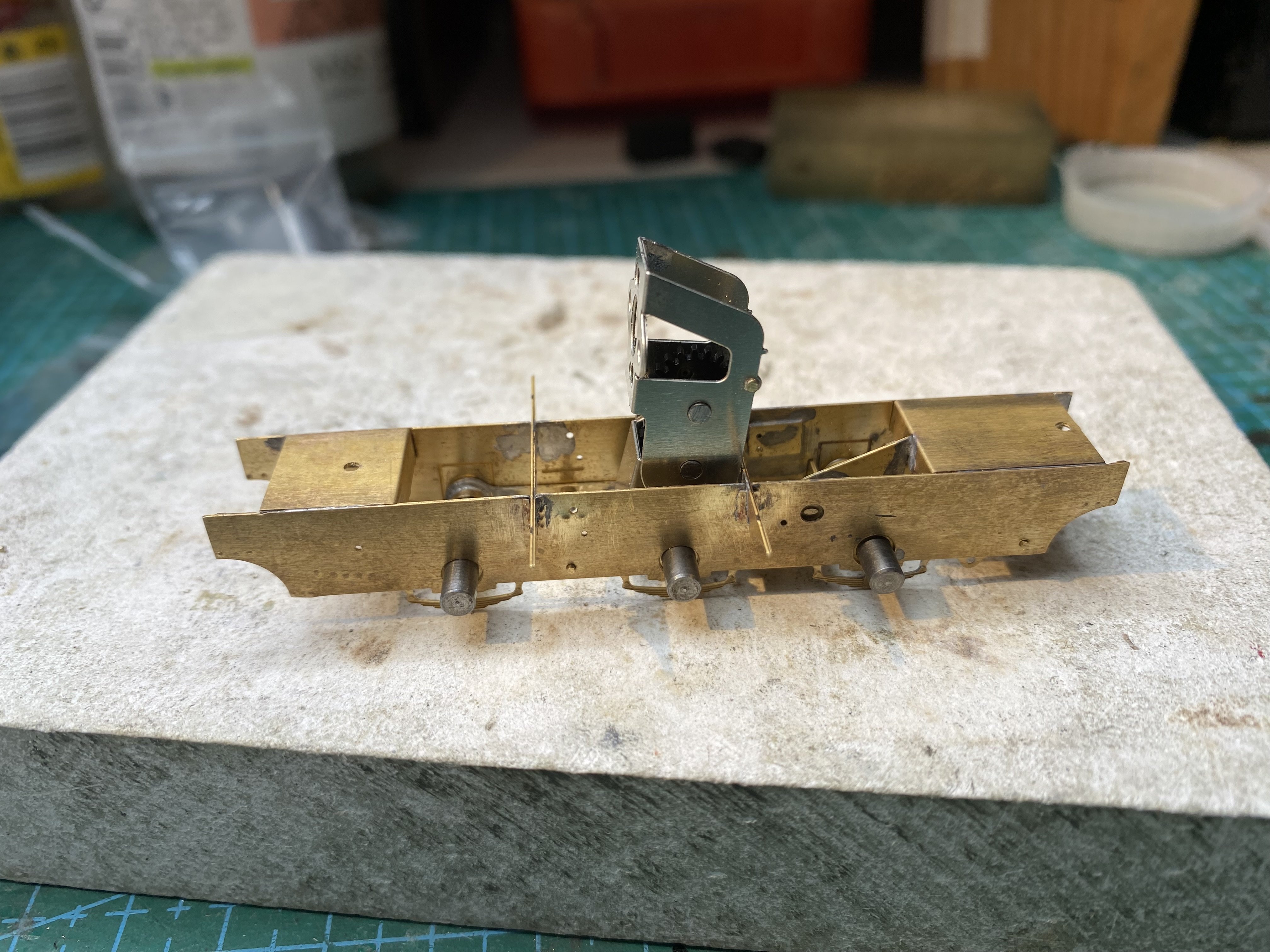
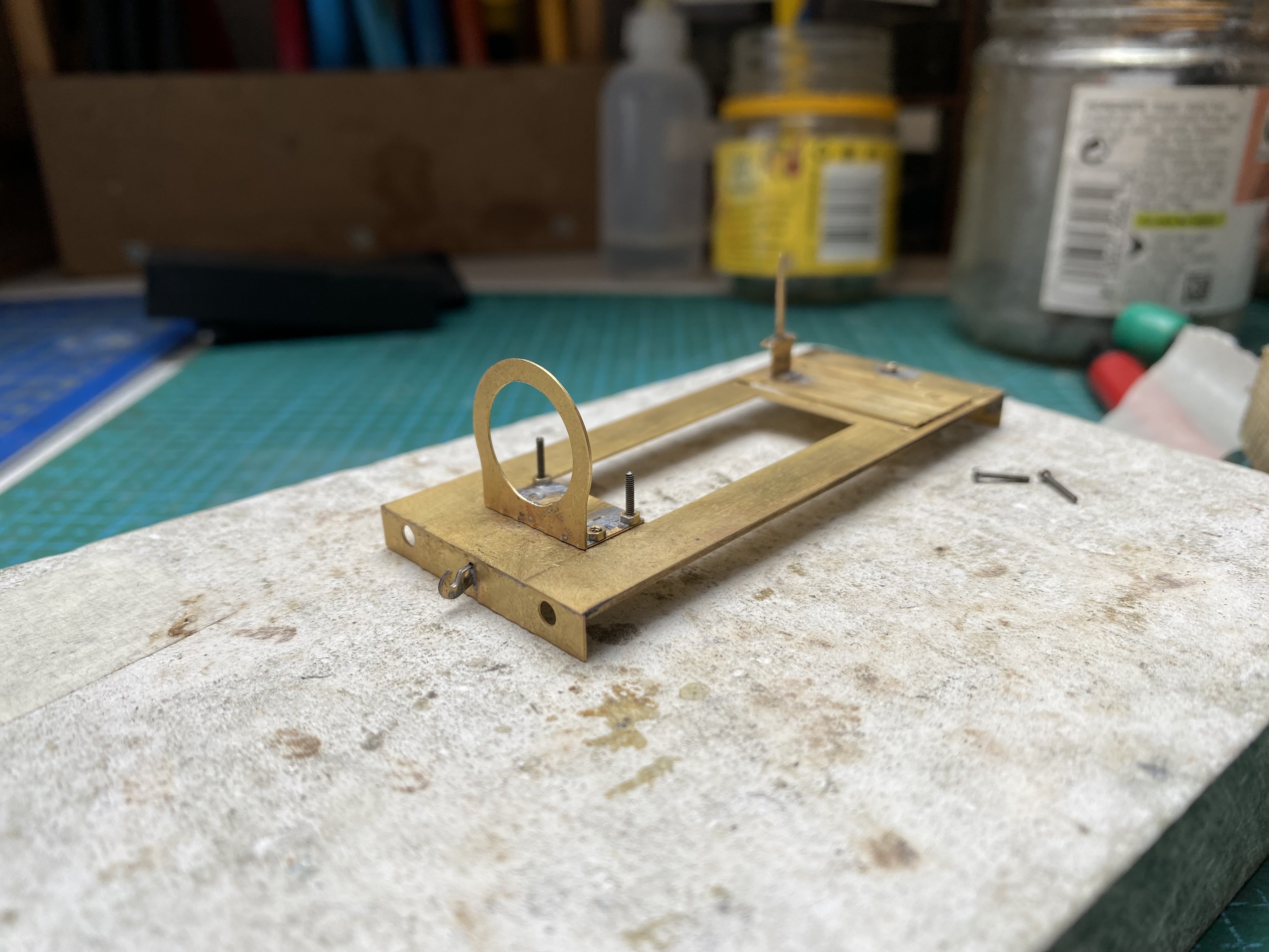
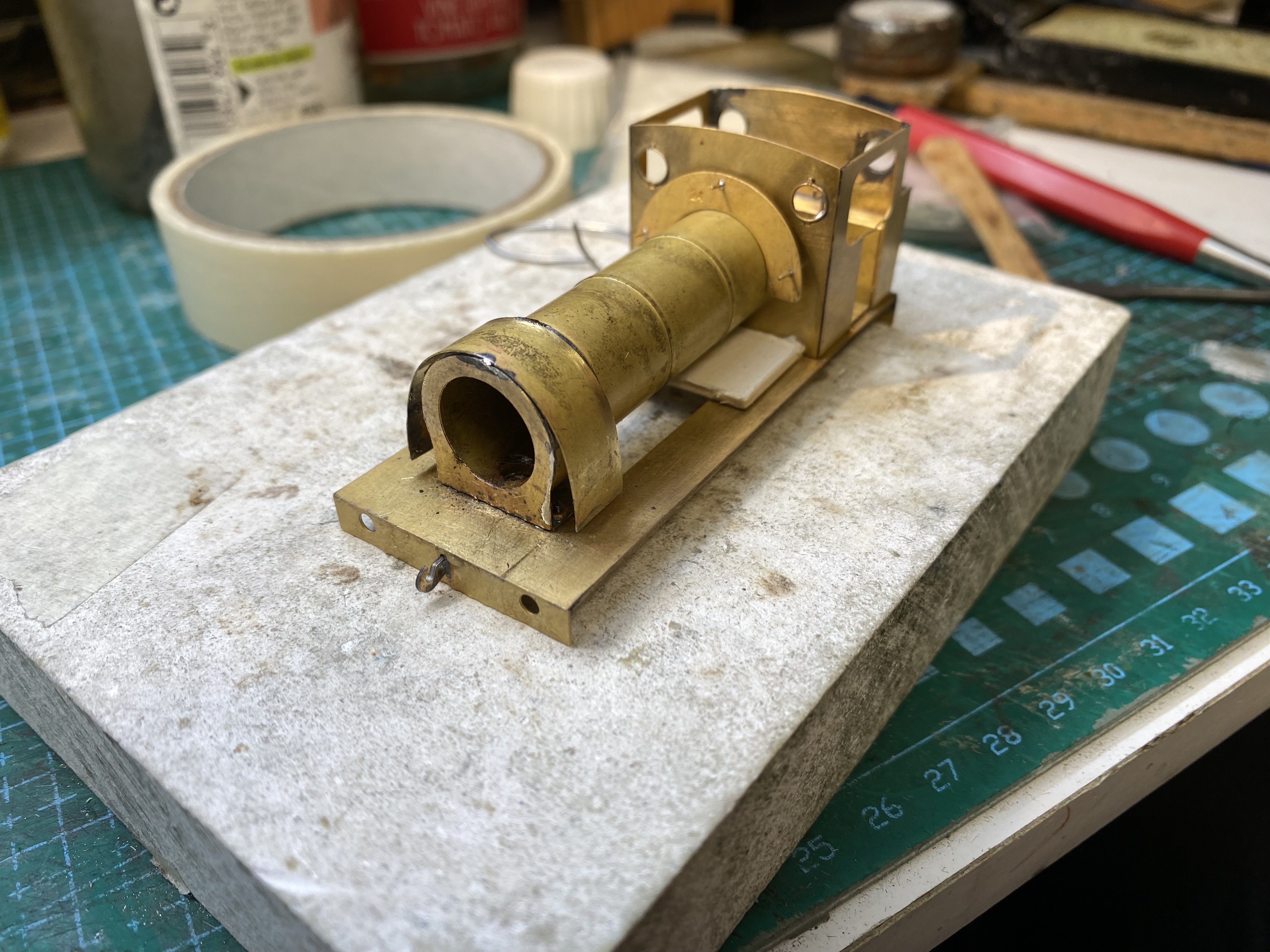
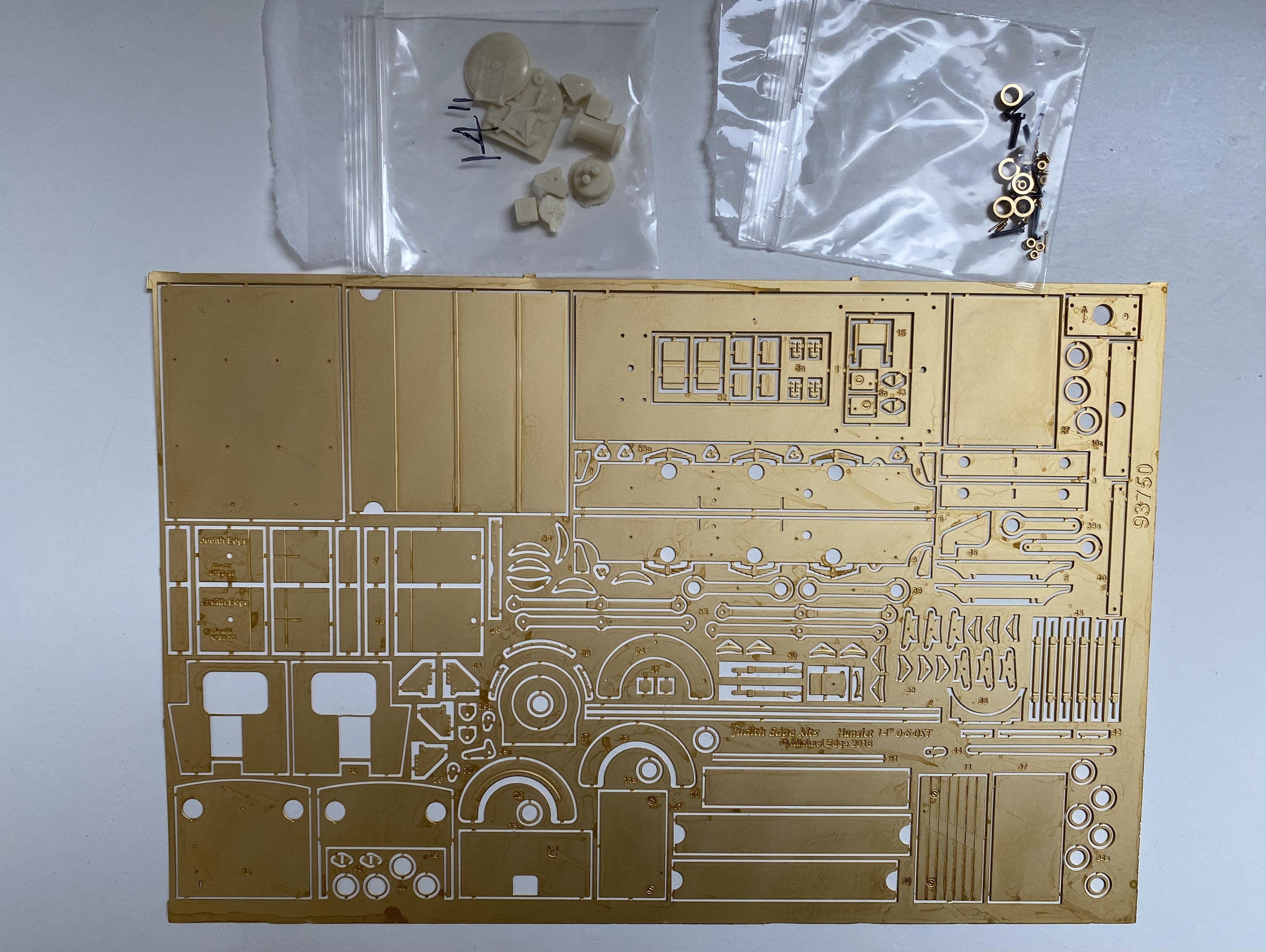
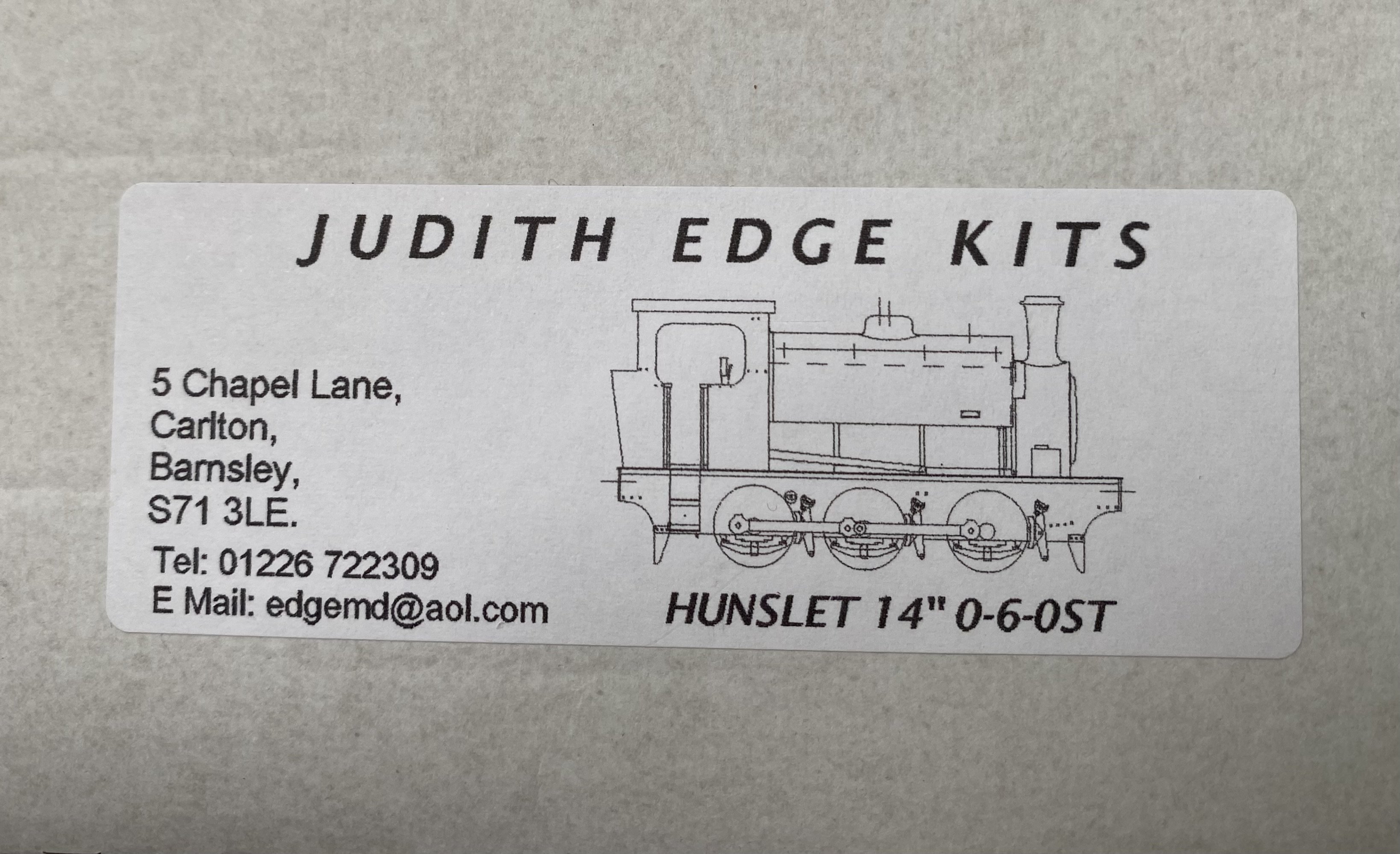
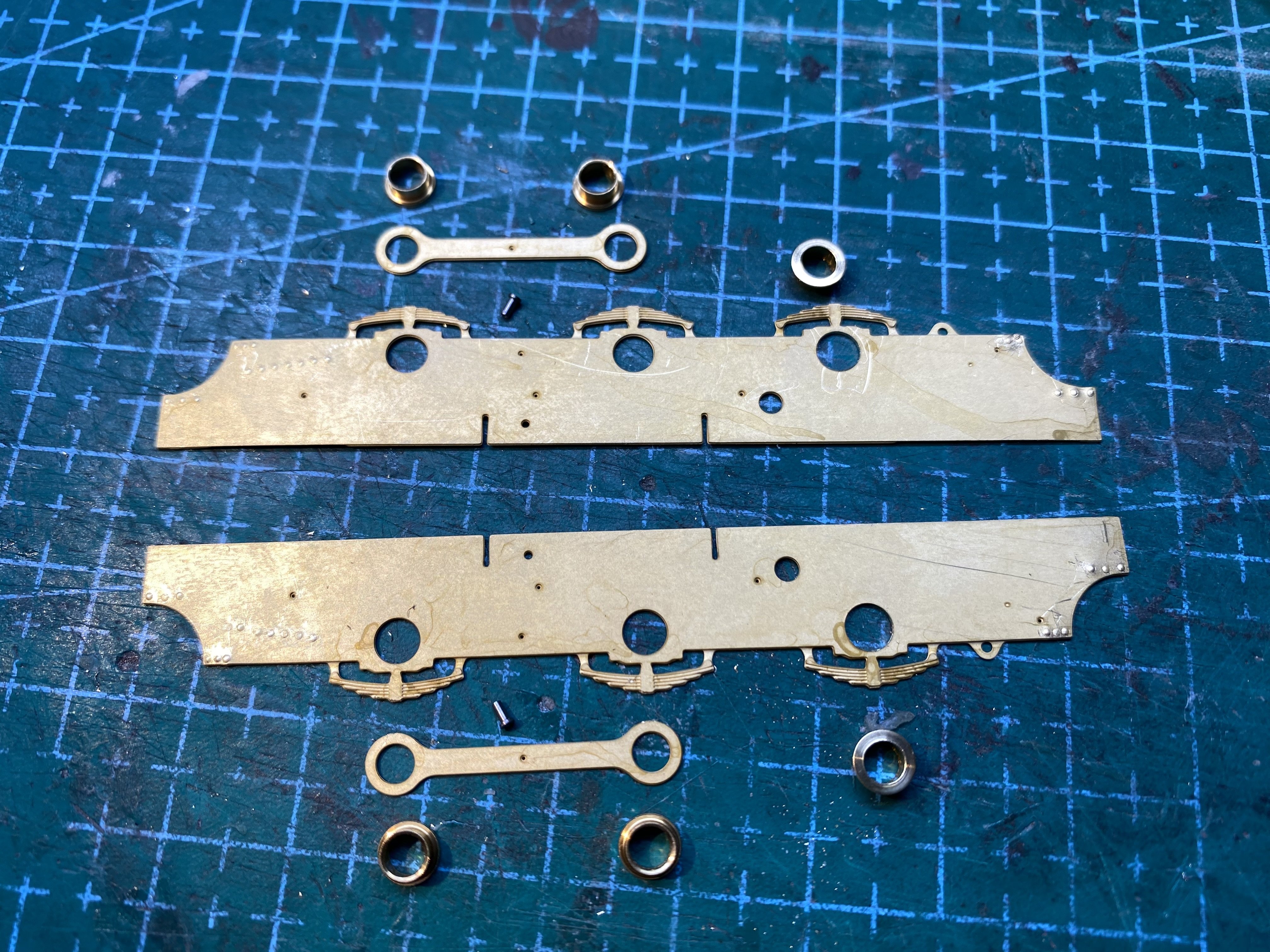
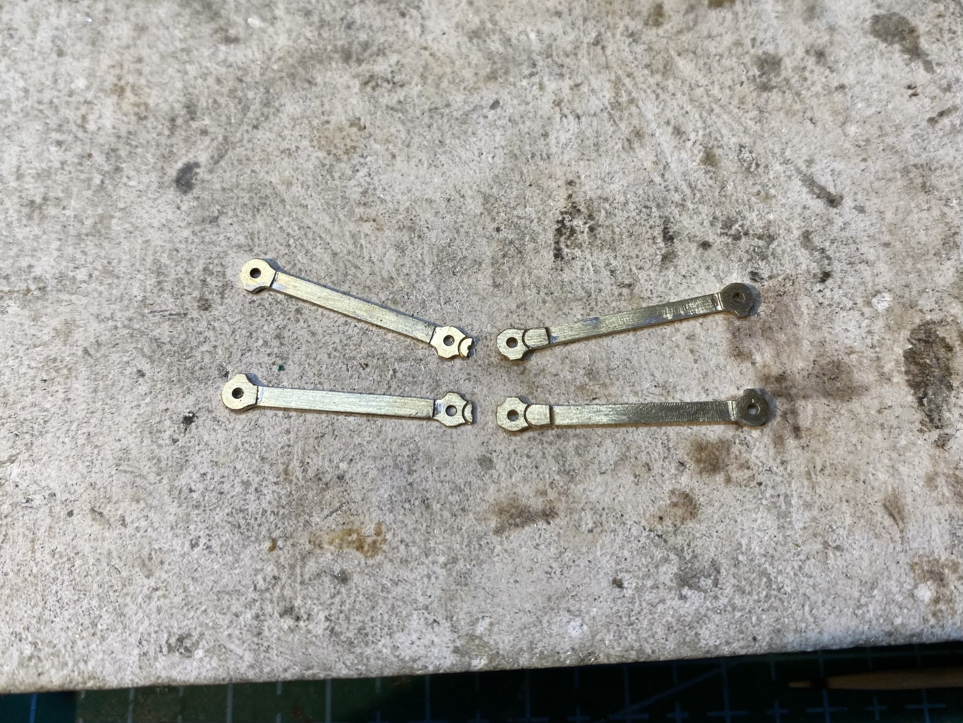
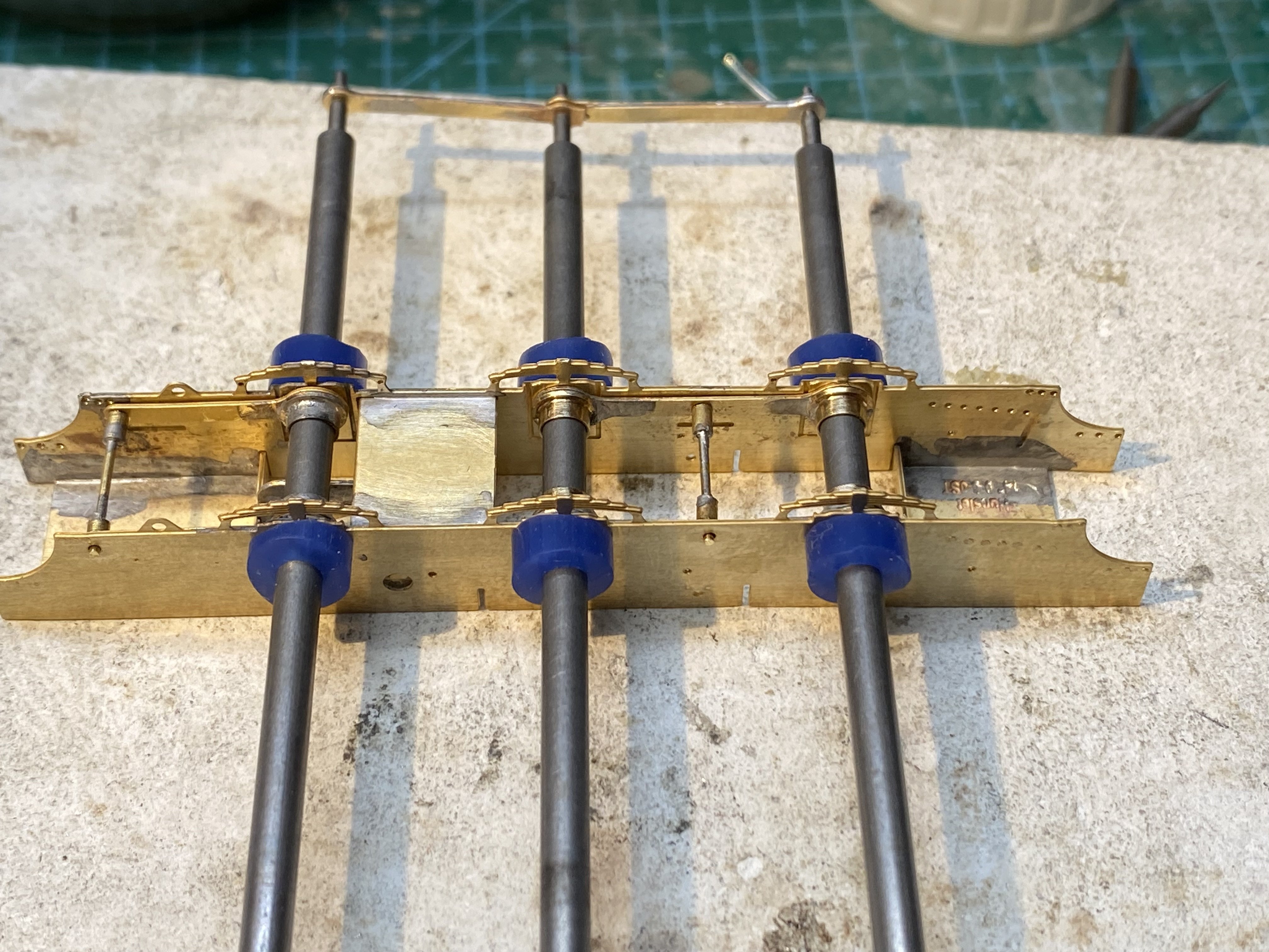
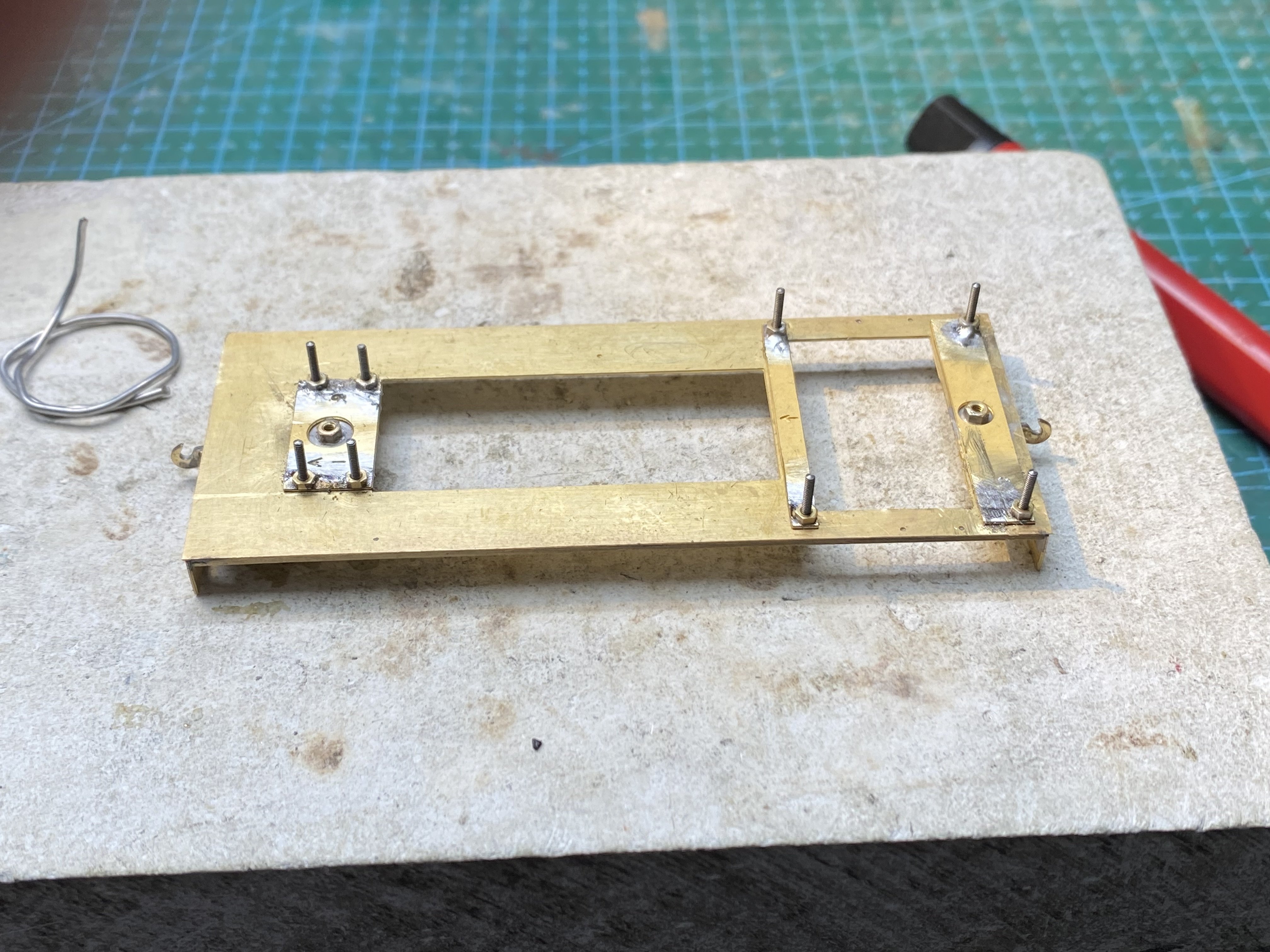
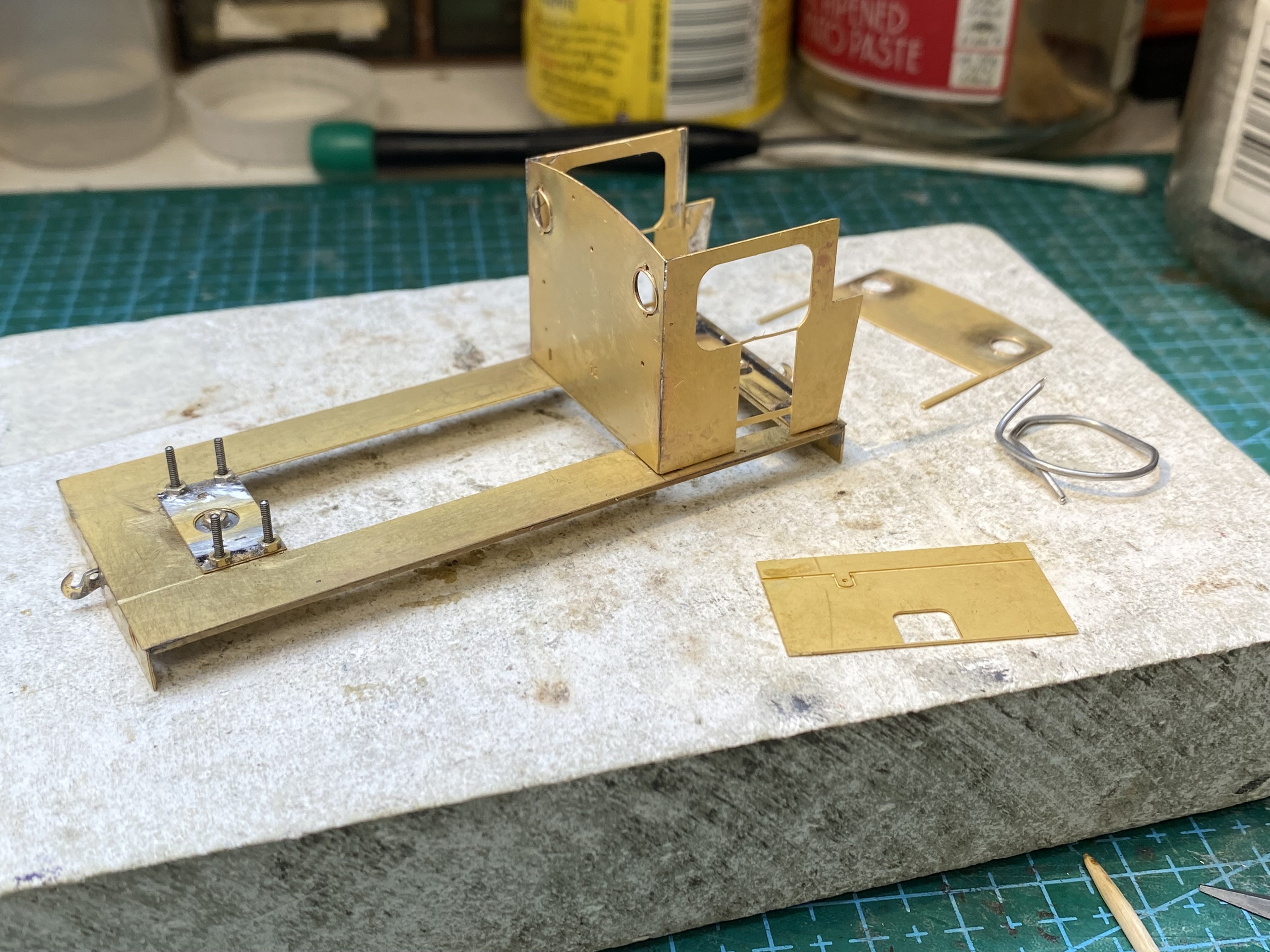
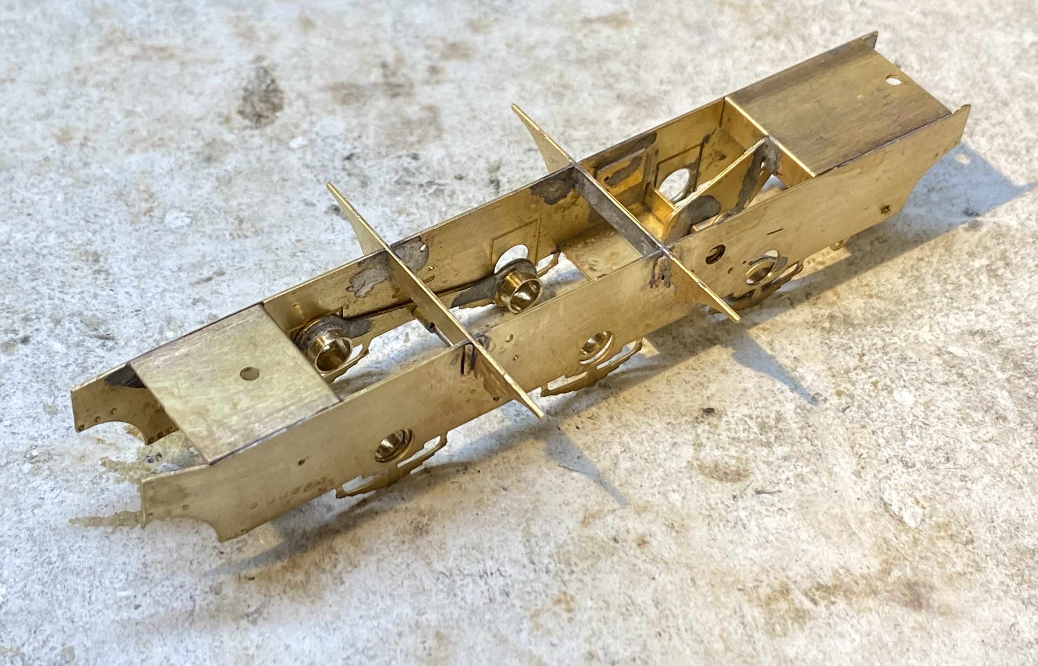
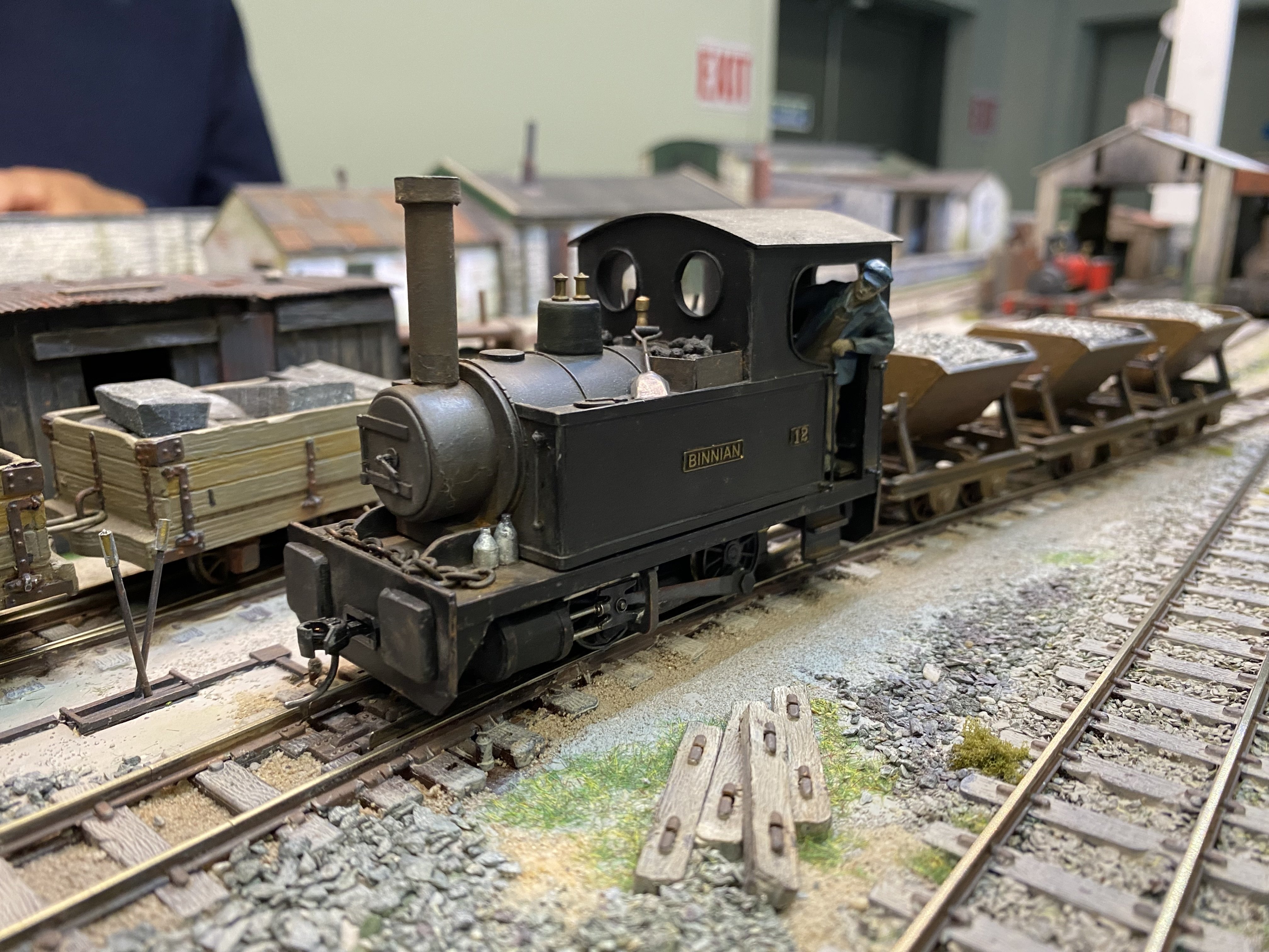
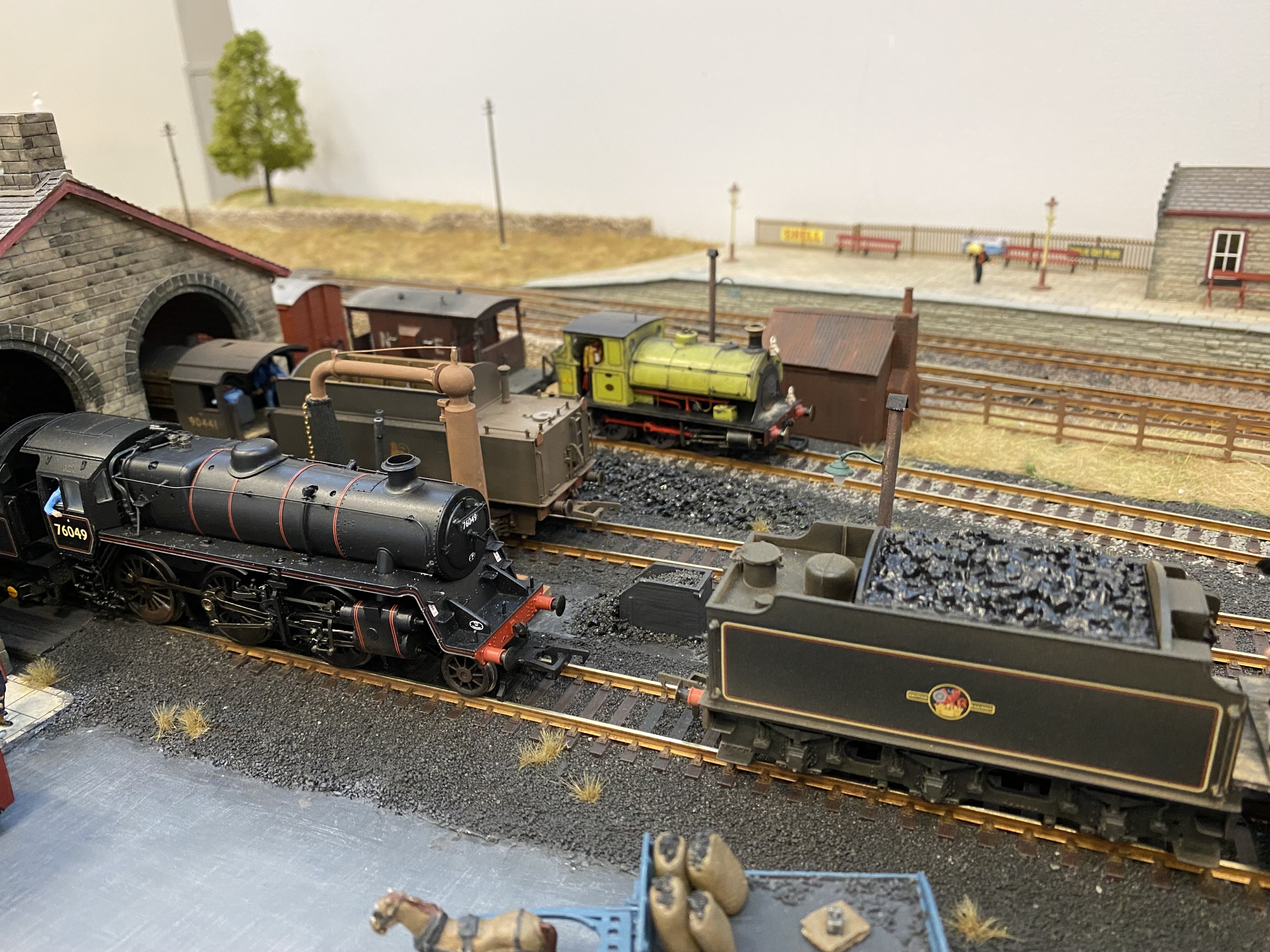
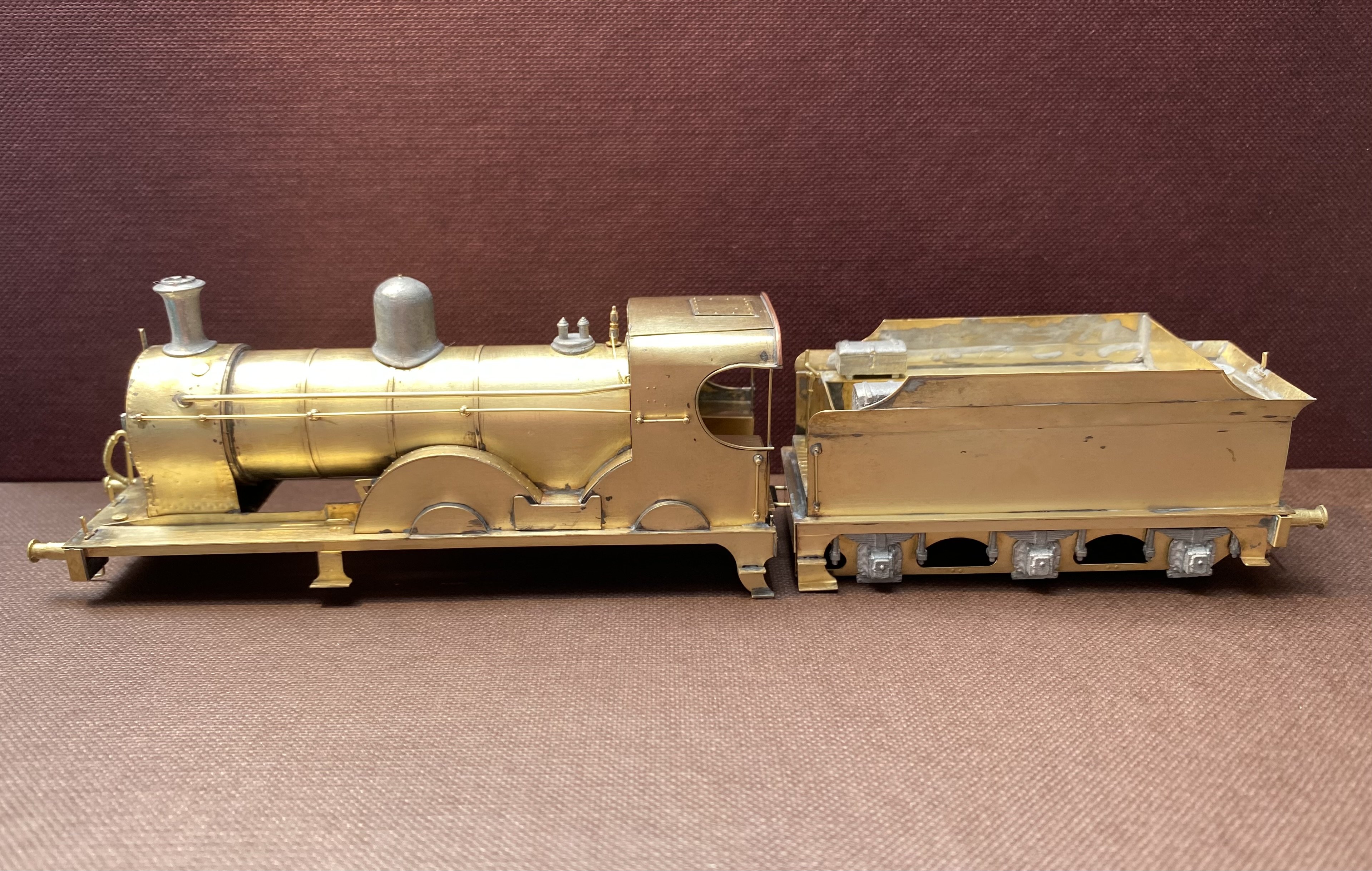
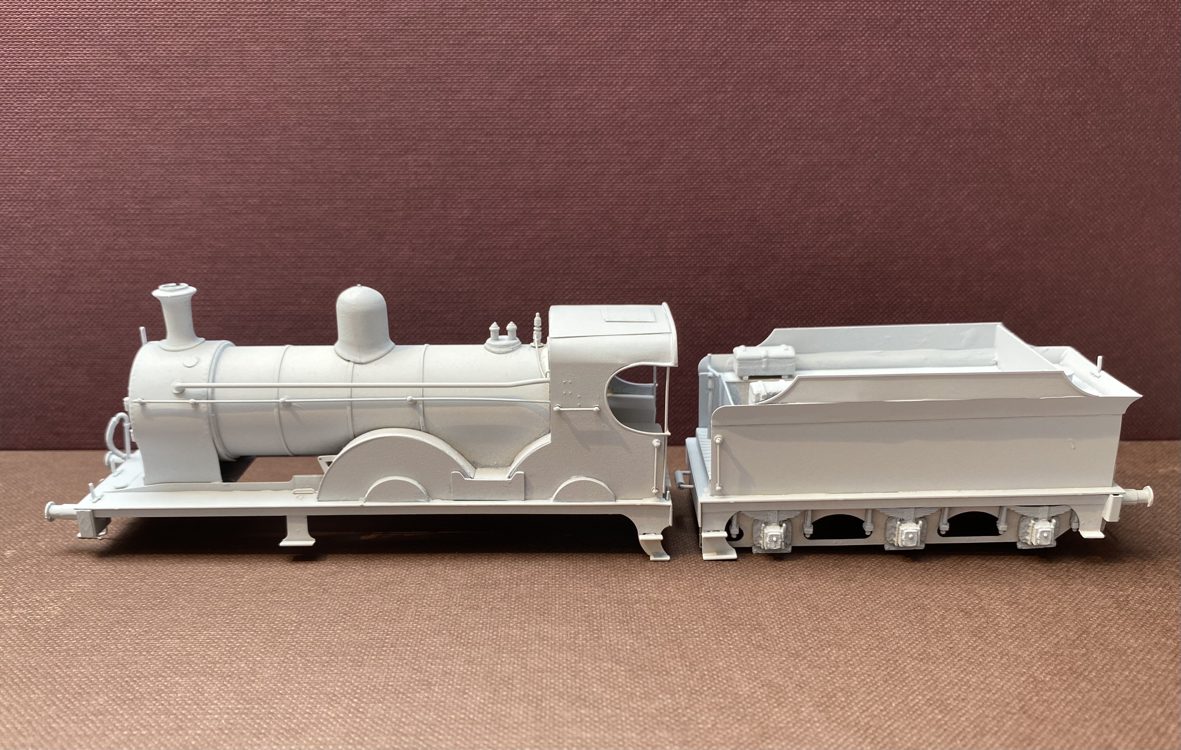
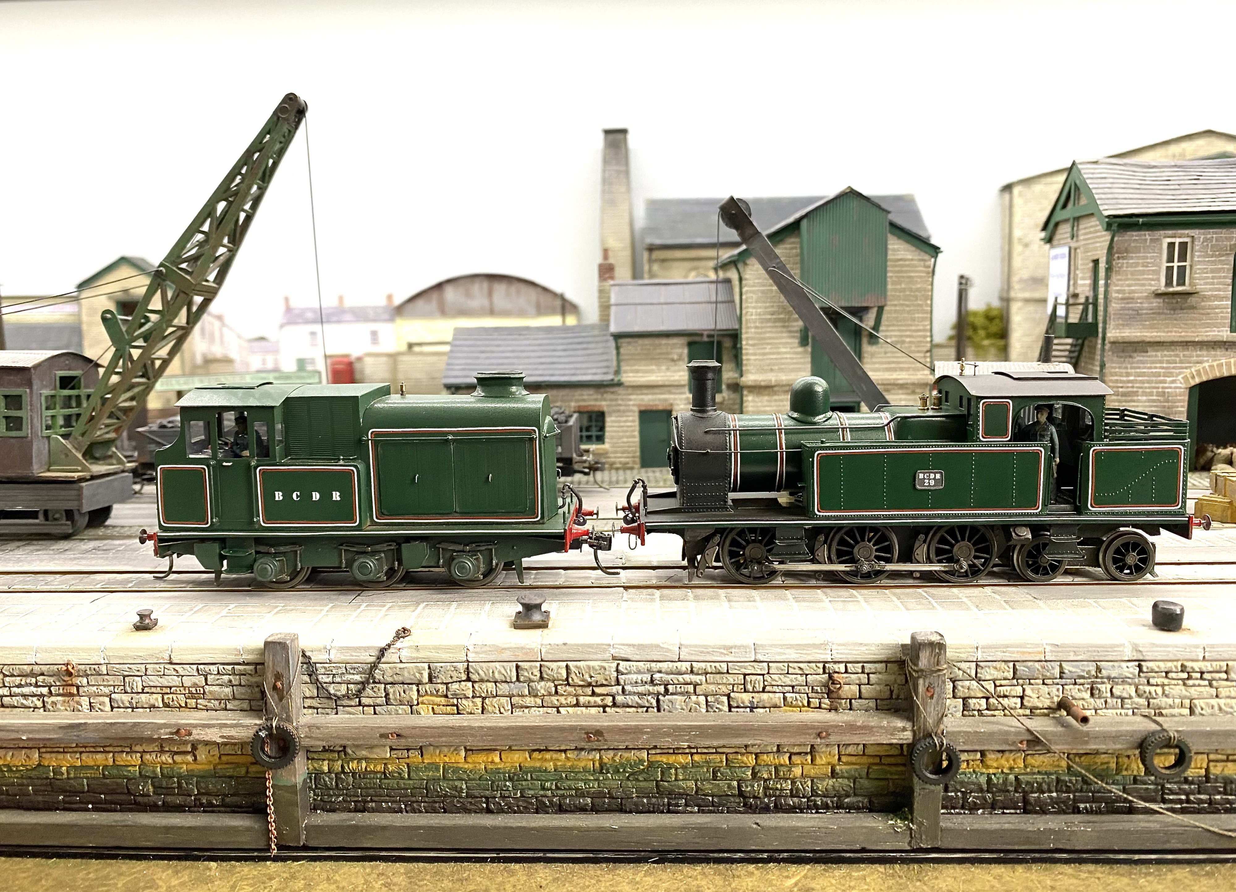
I changed the title of this thread rather than start a new one because what follows is more of the same really. After a fairly protracted period of building Irish locomotives of various persuasions and getting Kilmore, my BCDR exhibition layout up and running, I'm changing tack for a while and indulging one of my other interests - grubby little shunters, both steam and diesel. I've gathered a motley collection over the last few years with the intention of running them on an industrial themed layout which, to date, exists only on the back of an envelope. Anyway, here's the latest proposed addition to the roster. The kit consists of a single brass etch, some resin castings and all the necessary bearings, nuts, bolts and handrail knobs. Just add wheels, gearbox and motor. The chassis can be built rigid, compensated with all axles floating on pivoting beams or compensated with one fixed axle and hornblocks on the other two. Using hornblocks is my usual route and I intended to do that with this one before changing tack to try out pivoting beams. With hornblocks, the coupling rods are used as jigs to set the wheelbase correctly and so they get made first. Using the rocking beams method, the etched beams set the wheelbase so the rods aren't needed at this stage (the instructions don't mention making them until near the end of the build). However, old habits die hard... Chassis frame and rocking beams, pivoted in the middle, to hold front and middle axles. The beams for the rear axle aren't in the photo. Drive will be to the middle axle. A check after the event to make sure the wheelbases match the rods. I couldn't shake the notion that they mightn't! Chassis more or less complete. The vertical plate at the rear axle position is a knife edge on which the axle will rock. Footplate taking shape with baseplates for smokebox and cab. The 14BA nuts are captive, soldered to the plates so the body shell can be dismantled for painting. Lots of Vaseline under the plates and on the threads of the bolts to stop solder going in the wrong place and locking things up. it still did anyway once or twice, necessitating unseemly language, recovery and burnt fingers, in that order. The Resistance Soldering Unit came in handy to add the cab spectacle frames with a minimum of solder And this is as far as we got before bad light and the World Cup stopped play. More soon, Alan
- 42 replies
-
- 10
-
-
Mousa Models do actually offer etched kits for Irish coaches. Finding the list is the hard bit. First you need to be signed into the Mousa site. Then, Starting from the menu bar on the home page choose - Scales - Lists - Coach etching lists, Irish - Download now You should get this list. I've built the 3 BCDR coaches. They make up into nice models. Don't expect instructions though Alan
-
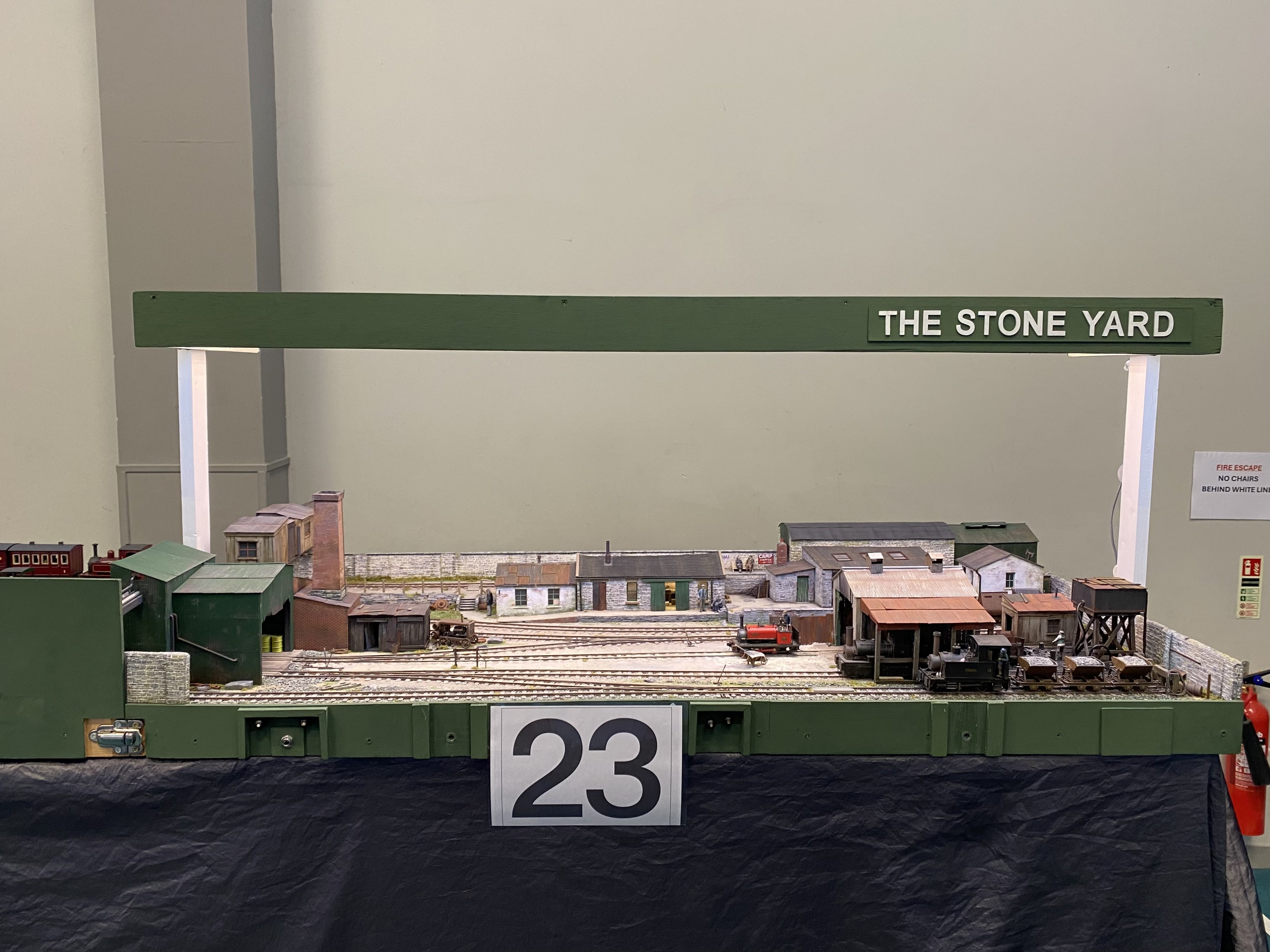
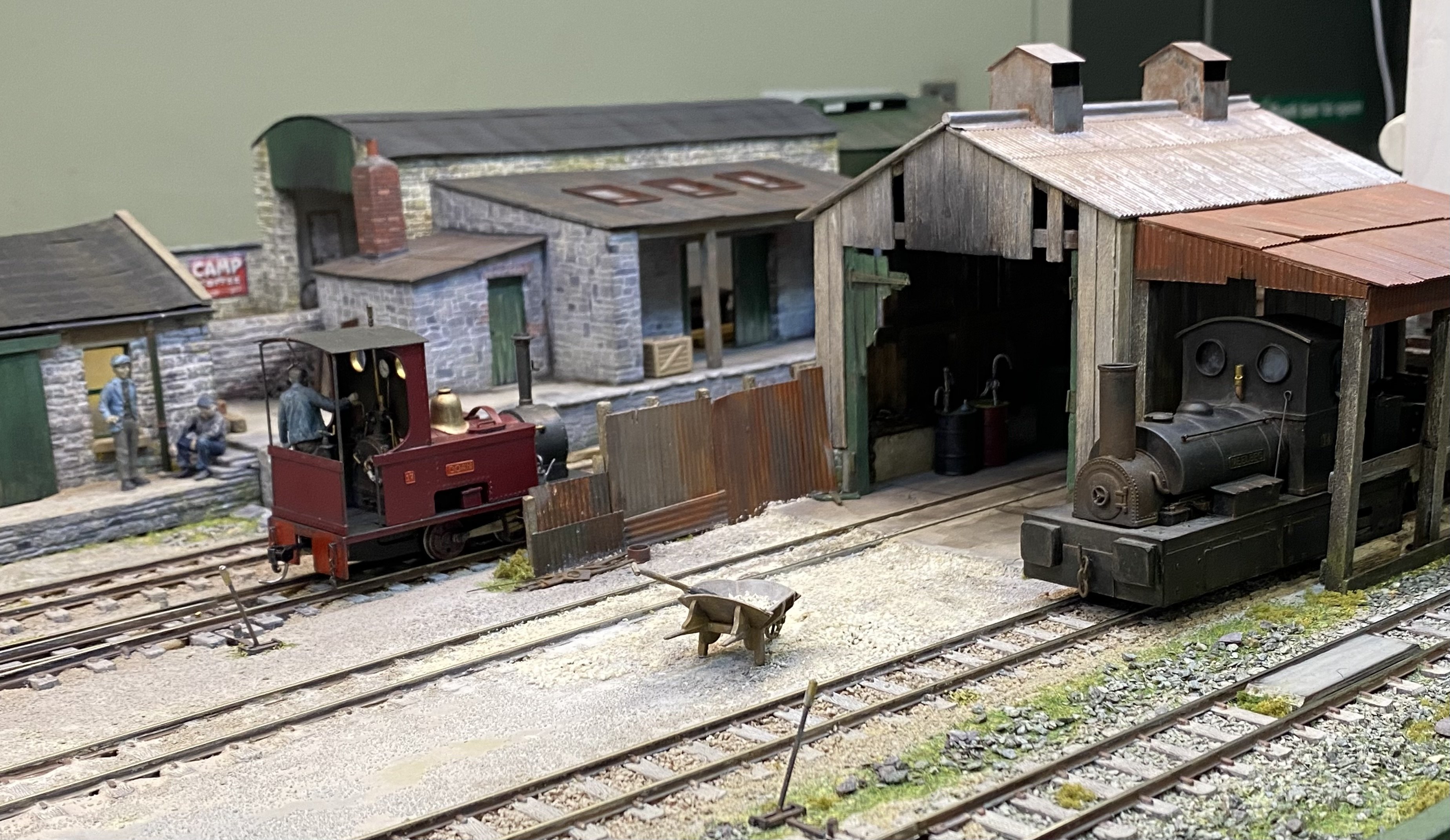
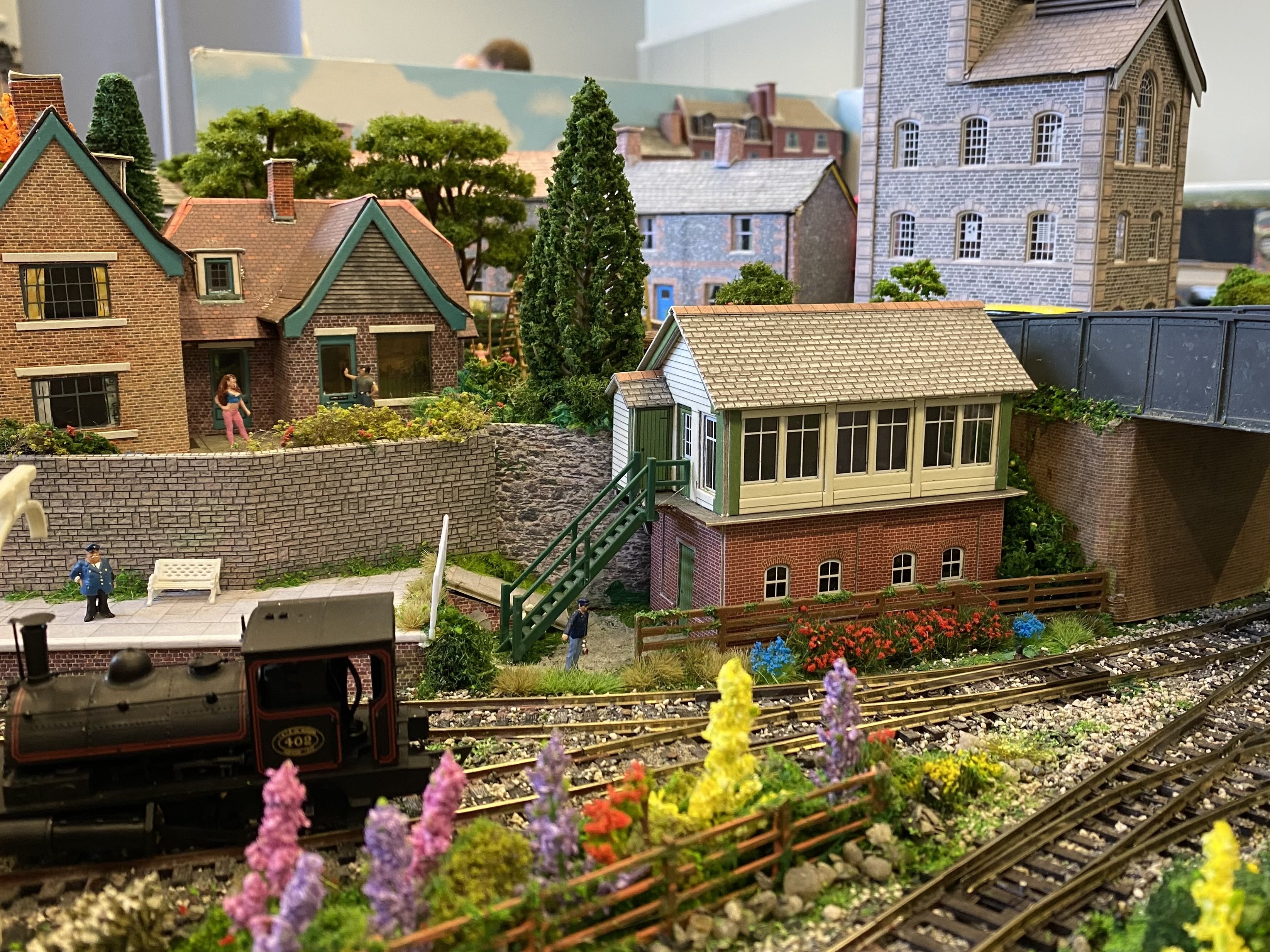
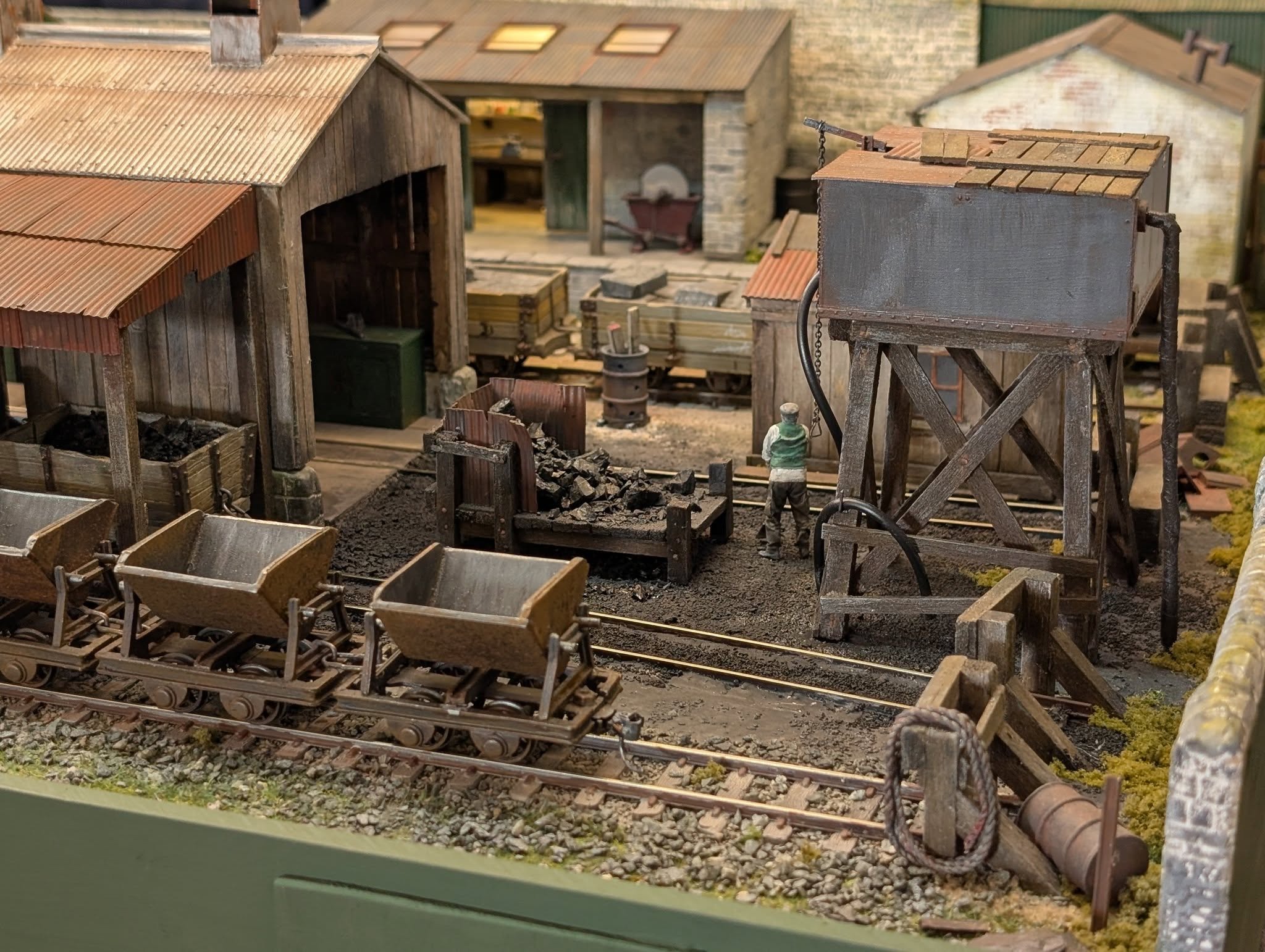
The Stone Yard made it to Glenabbey MRC's exhibition today. Great venue with good parking close by, a bright, spacious display space and a friendly welcome. Couldn't ask for better. The layout behaved itself all day. Kieran and I can operate it in our sleep now and we also had a number of visiting operators in the 6 to 10 years old group during the day all of whom took to it like ducks to water. One little lad mastered uncoupling and coupling Kadees in about 30 seconds. Took me weeks to perfect that! Many thanks to GMRC for the invitation to be part of this one. I hope you'll make it an annual event. Alan
-
Some photos from Glenabby MRC's 10th anniversary exhibition today. Congratulations to the club on a great show and a great venue. Hope this can become an annual event.
- 1 reply
-
- 8
-
-
Thanks Phil. I must admit it has a special place in my affections too. I hugely enjoyed building it. Alan
-
Time for The Stone Yard to come out to play again. Currently getting spruced up for an appearance at the Glenabbey MRC exhibition this Saturday 20 June 2026, 10.00 -16.30 Glenabbey Church, Ballygraigy Road, Newtownabbey, Co. Antrim, BT36 5ZZ Alan
- 118 replies
-
- 12
-
-

-
Time for ThreePee to get a workout on the rails Clattering through some Peco three-way points without falling off... IMG_5205.mov ... and stretching its legs at Kirley Junction. Thanks Kieran. ThreePee at Kirley J.mov Scrubbed up and ready for primer.... .. et voilà! Nearly time to go to its owner Patrick @Patrick Davey for top coats. I'll refit the chassis after that's done. Alan
-
Still having to remind myself to check this corner of the forum. Delightful. Just oozes atmosphere.
-
Hope not Patrick. Maybe your postman will just leave it on the doorstep. I have a plant pot on my doorstep for mine to hide parcels behind.
-
Agree absolutely David and all of them interlinked so changing one thing affects other things and you're never quite sure what the root of the problem actually is. You can spend whole afternoons going round in circles. There always seems to be a low point when everything you try seems to make things slightly worse. Why do we do it? Well... there's the challenge - "I won't let this little brute beat me" but also the satisfaction of looking at a nicely finished, smooth running, hand-built gem and thinking "I did that!" It can be hard though to remember that when the little brute is fighting you tooth, nail, hornblock and coupling rod. My current little brute, Patrick's 4-4-0 PPs, has decided to behave itself again after a frank and prolonged exchange of views during which it was shown the big hammer. Smooth, slow running restored in both directions. Long may that continue. IMG_5172.MOV Now, where did I put the rest of it....
-
I think it’s been a catalogue of things, among them wheels out of true and a possible bent crankpin. Anyway it’s performing better now so I’m about to tiptoe quietly away for now. many thanks for the support lads
-
Not silly at all David. Yes they are. They were painted in situ though I've just now taken them off and re-fitted them. That's an interesting thought. Worth a try. I originally spacered the back axle so there was zero sideways movement. I've now taken the spacers out to allow it a bit more freedom. It seems to have improved things a bit.
-
The geartrain looks pretty clean and with the final drive grub screw loosened, it runs like a sewing machine in both directions. Can't see anything rubbing and yes the motor is fine. Thanks for the prompt response gents. Appreciated. I put the rods back on and I think one is coming up tight at the same point in each rotation. Thought I'd sorted all that. It may be because some of the wheels are very slightly out of true so the crankpins bind on their bearings. I'm not keen to ream the rods too much more. There's already a fair bit of play. A wheel out of true could account for the odd behaviour on the rollers.
-
ThreePee, having behaved impeccably up till now, suddenly developed a stutter going backwards. I am at a loss to understand why. This is it on the rollers, coupling rods disconnected and this is the driven back axle. Anyone any idea why it's doing this? Doesn't do it going forwards. IMG_5167.MOV
-
Thanks for this. It does seem they need very careful handling. Hope you can get your 08 sorted with new rods.
-
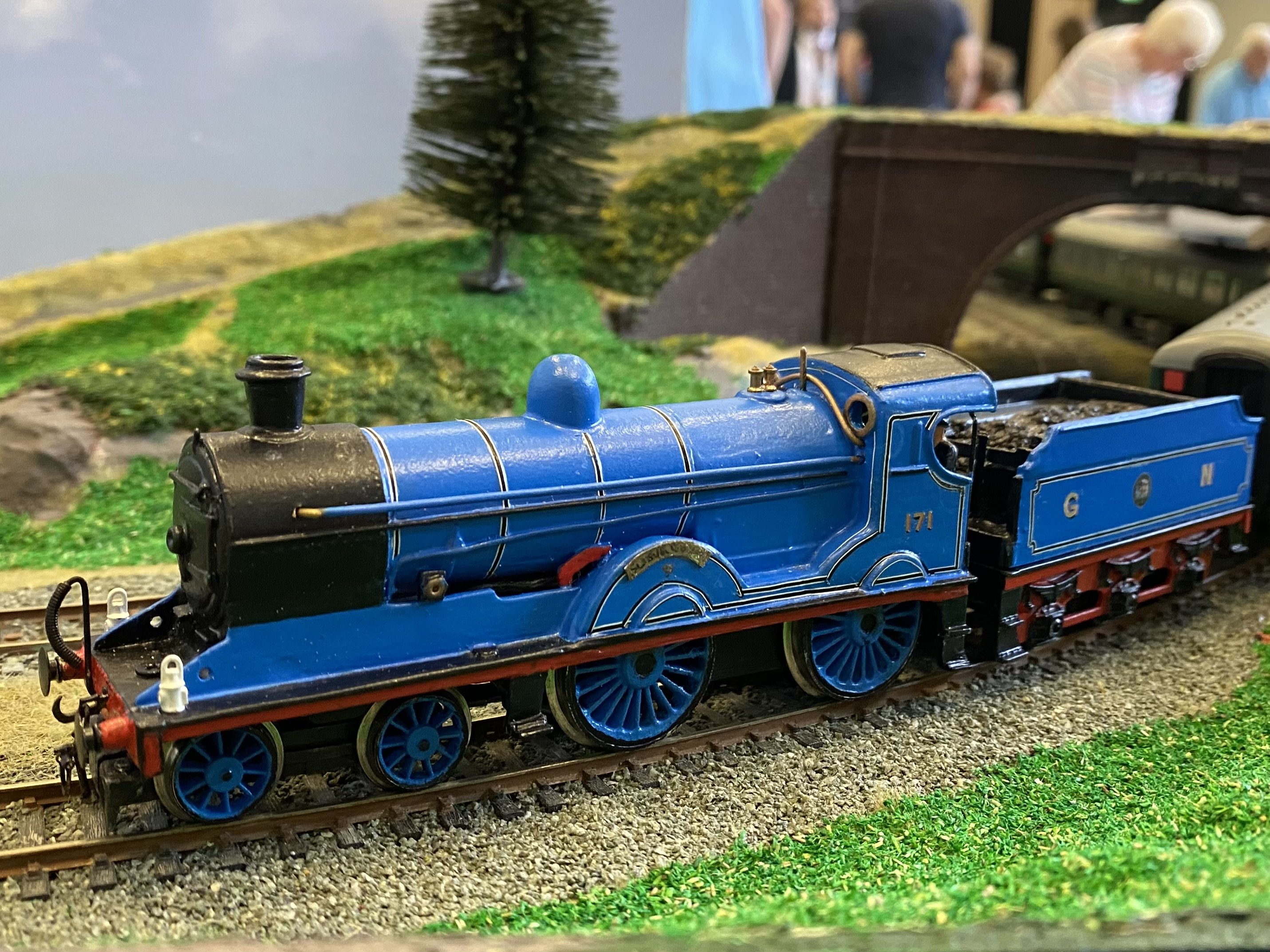
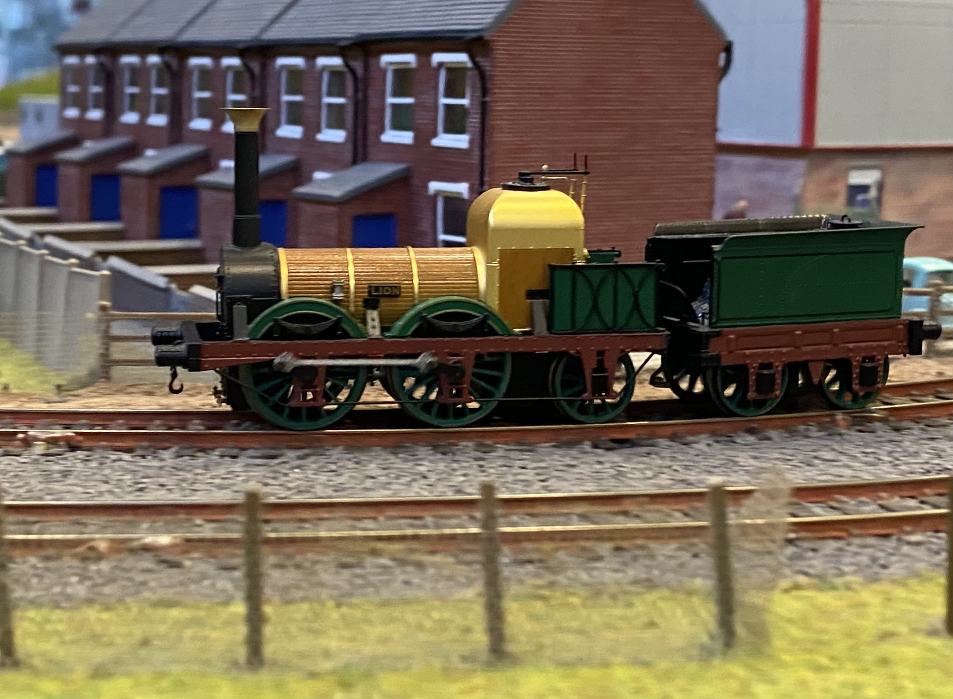
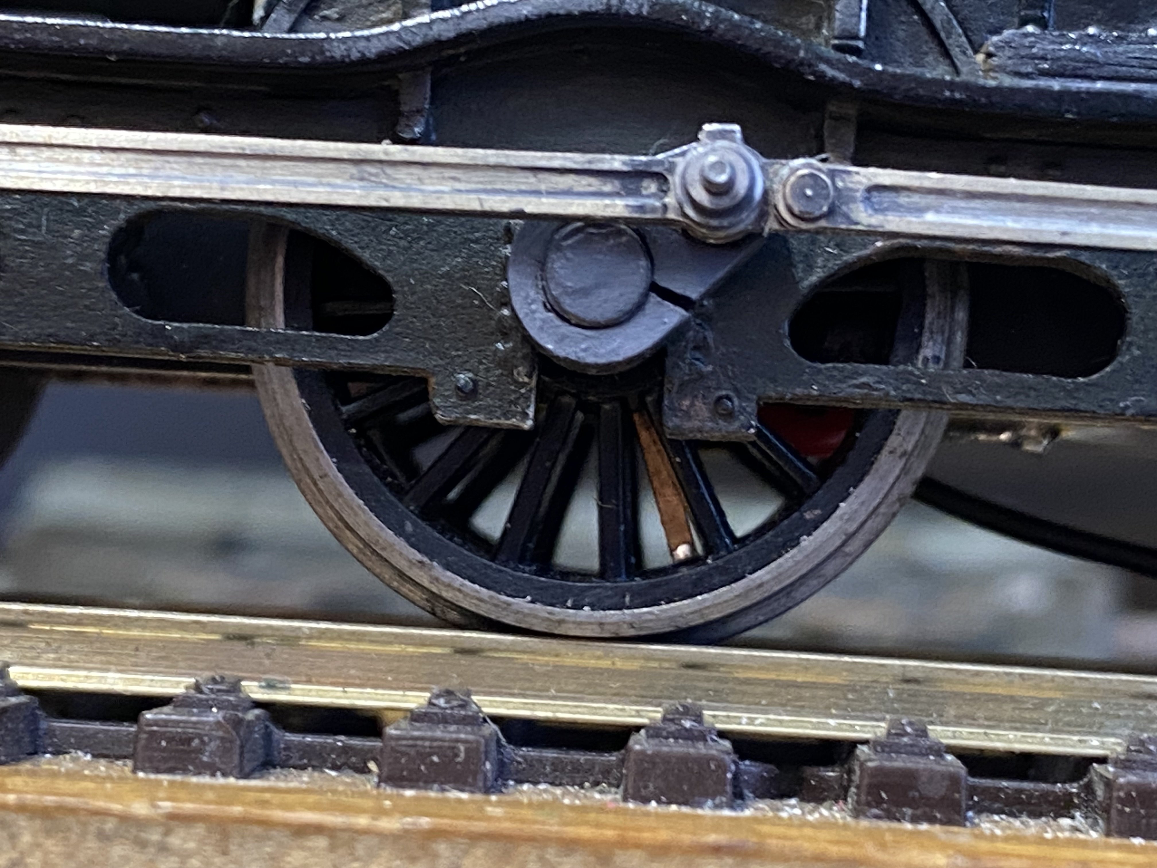
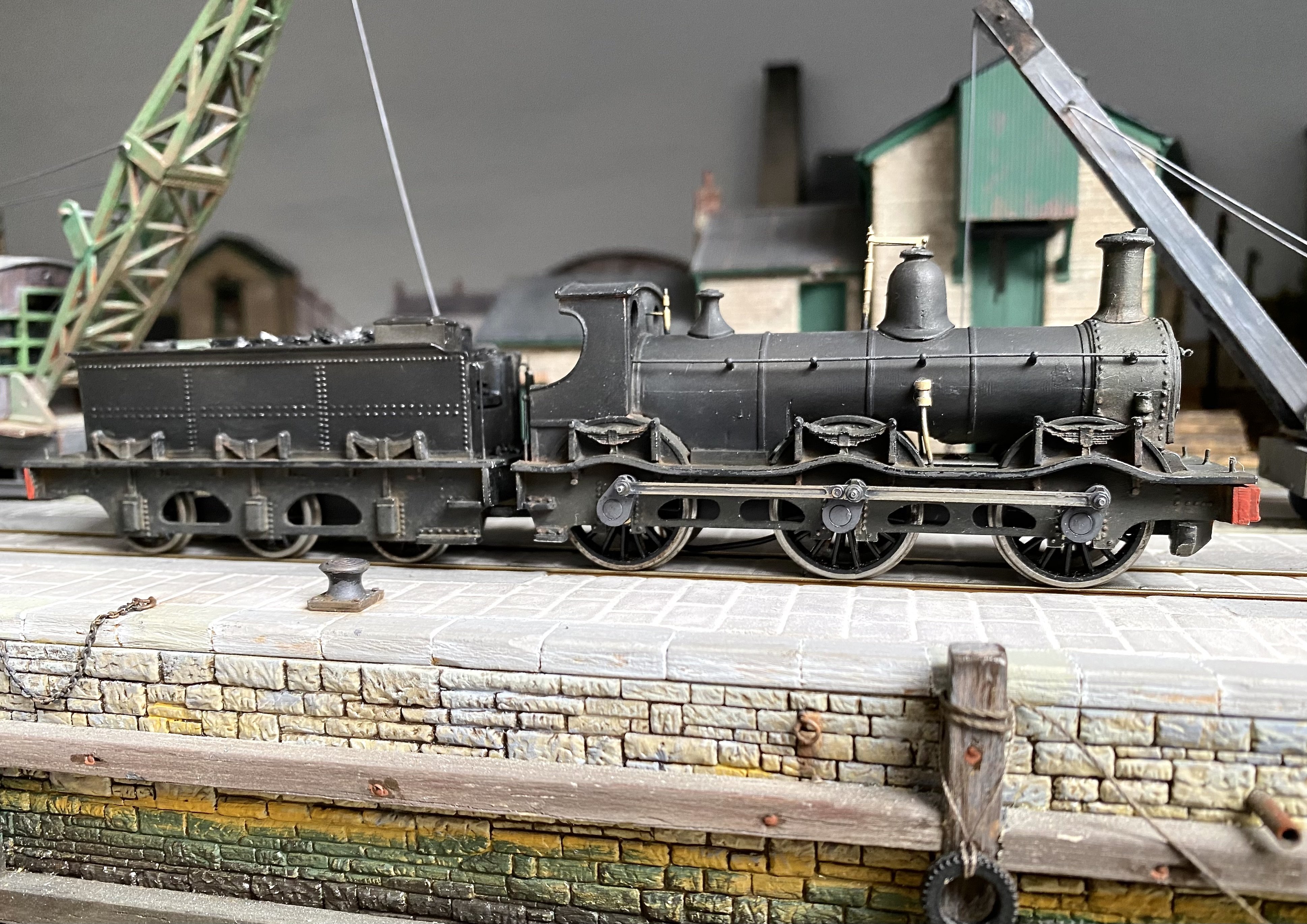
In between times, I've been dabbling with my Kirtley project using bits of the old K's kit as a starting point. With all the messing about, the original wheels were getting looser and looser on the axles calling for drastic measures. The live ones are soldered to the axles via the shorting spiders. The insulated ones were reamed out to allow a standard 1/8" axle bearing to be epoxied in and these were then soldered to the axles. A new set of Gibsons outside cranks were fitted to replace the ones that I managed to split. It'll never be a great performer with its wobbly wheels but at least it does run. IMG_5008.MOV It's been painted and weathered now. Still needs buffers and a crew but it's just about finished. However, when I was setting it up for some photos, I discovered that one of the new cranks had split! I was so careful this time, easing them out with a broach and bevelling the rear before fitting them. I don't know what I'm doing wrong. Anyhow, with another superglue repair, it still runs but it's probably one for the display cabinet. Here it is in all its glory. Alan
-
Nearly there Patrick. Not too much longer I hope