Tullygrainey
-
Posts
934 -
Joined
-
Last visited
-
Days Won
55
Content Type
Profiles
Forums
Events
Gallery
Blogs
Store
Community Map
Everything posted by Tullygrainey
-
It does Leslie but it leaves you with nothing to blame
-
I think my learning curve mirrors yours David. I can remember not that long ago thinking that, even though the idea really appealed, building etched kits would be beyond me. And I still have the first Branchlines chassis I ever assembled. It never ran properly, and has defied subsequent attempts to make it work, but I learned a lot from it, not least that it was worth trying again. So Patrick, I have a spare soldering iron if you want to borrow it Postscript: Reading this back, I need to add that the failure of my Branchlines chassis was nothing to do with the design of the chassis and all to do with the cack- handed actions of a beginner-builder! Alan
-
Never say never Patrick. We’re all on learning curves here. That’s part of the pleasure
-
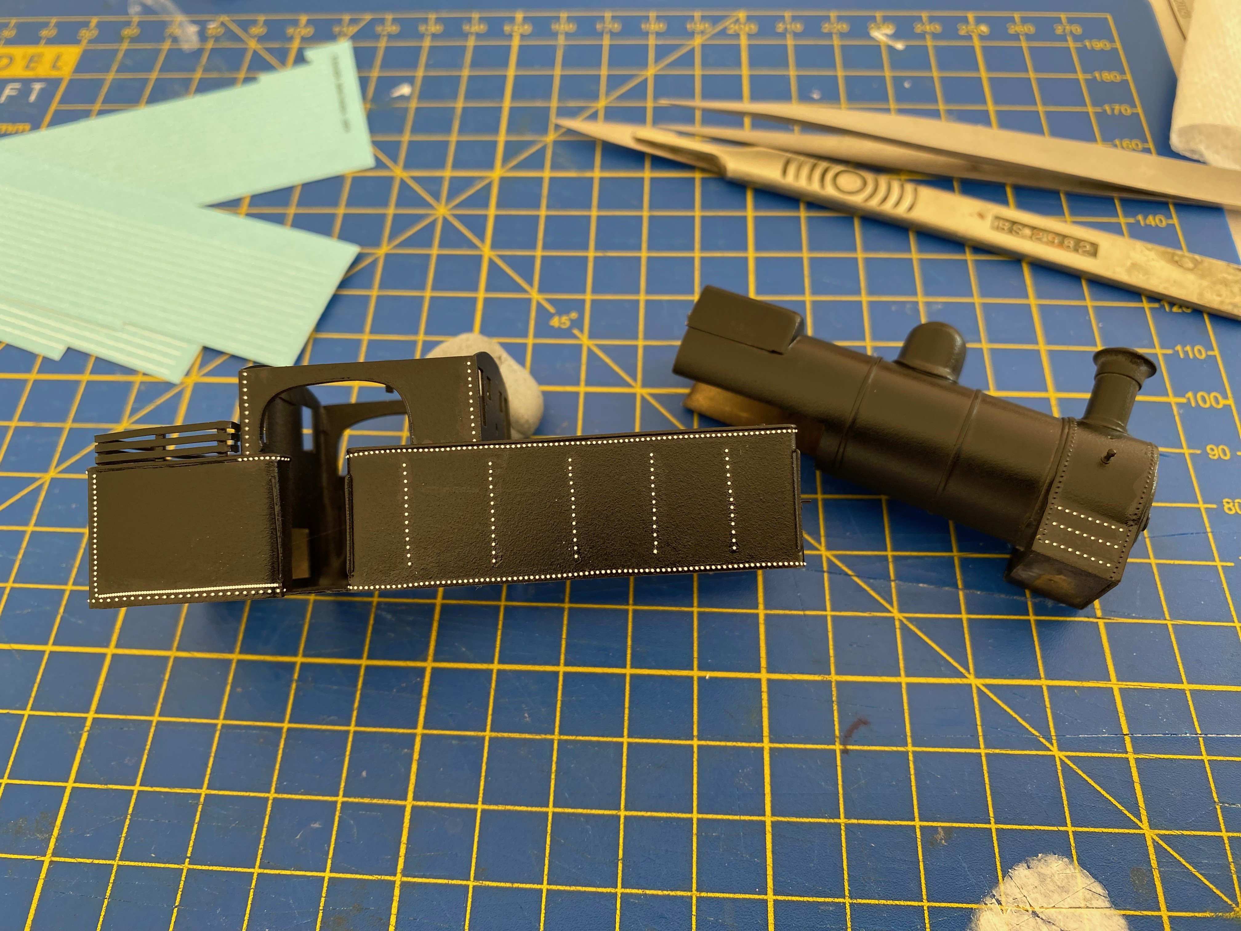
Bye bye brass Managed to get away with not too much filling. It's very grey isn't it! Actually it's now black to give a good dark base for the green topcoats when we get to them. But before that.... More Little Things Sent To Try Us: Rivet transfers My first use of Railtec's 3D rivet waterslide transfers. They come in a range of sizes and spacings and are beautifully crisp but extremely delicate so they need very careful handling. Moulded in white, they're easy to see against a dark background. By the same token, any irregularities in applying them are horribly apparent in photographs, especially in long runs. Witness some of the wobbly lines above. This should be less apparent once the paint goes on and the rivets are the same colour as the background. I hope. The larger black rivets on the smokebox are from my remaining stock of Archer transfers. Putting black rivets onto a black base was a laugh. Alan

- 613 replies
-
- 16
-

-

-
Out of adversity comes innovation! Nice work with the buffers and couplings David. Fly is looking pristine again. I get the same feeling about that first paint coat - too bright and too shiny too in my experience. Toy-like. But it soon comes in, as you say. Looking forward to seeing Fly gather a little road dust. Probably best not to think too much about the cost. It’s a small price to pay for the pleasure of building something and then looking with a bit of pride at what you’ve achieved. I think Fly has come in at a very reasonable cost. One of the advantages of taking as long as I do to make anything is that the cost is well spread out and less noticeable Incidentally, my most recent 4mm rtr loco purchase cost £325 including postage. I don’t do that very often. More power to your soldering iron. And your Black & Decker Alan
-
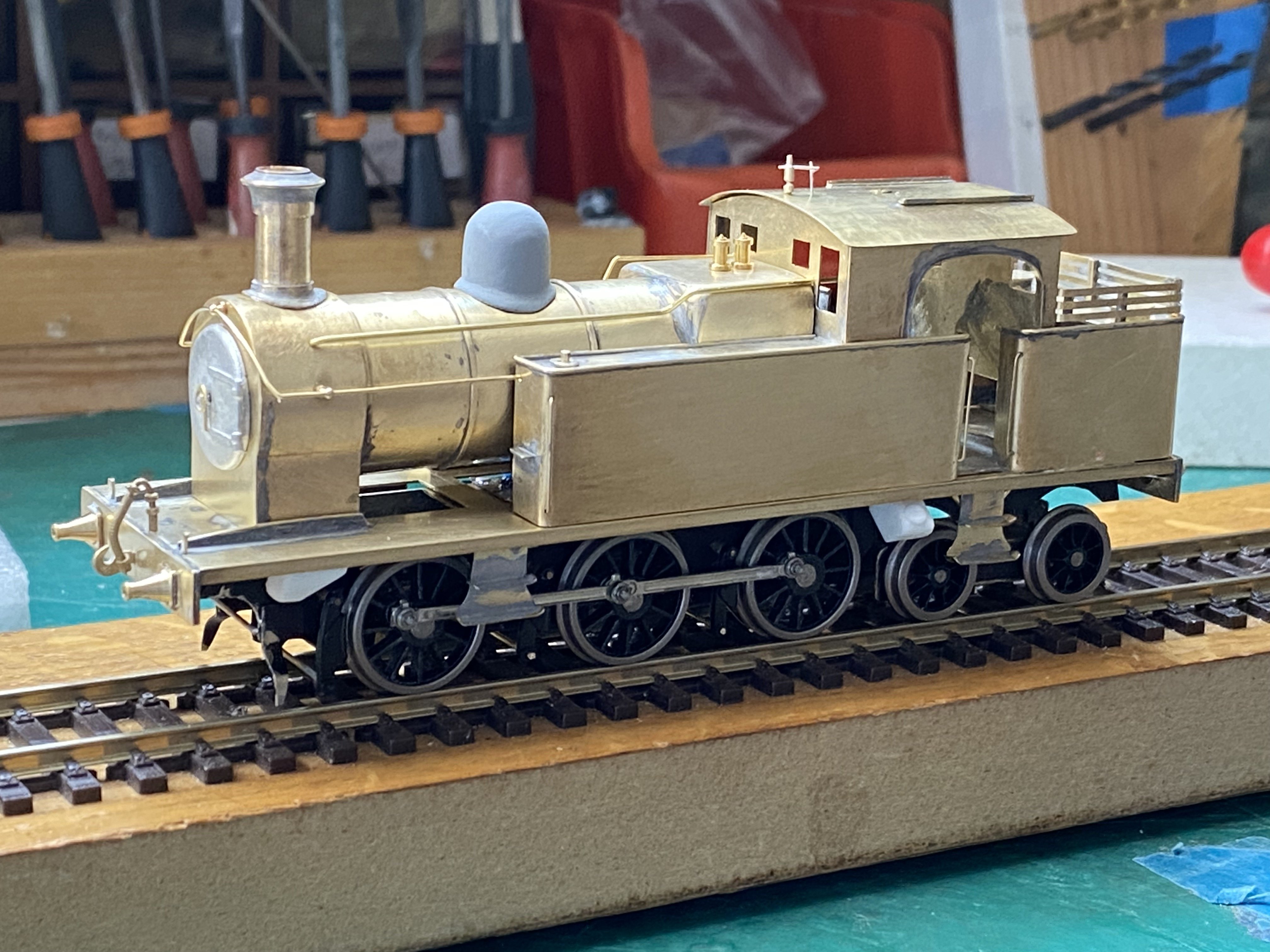
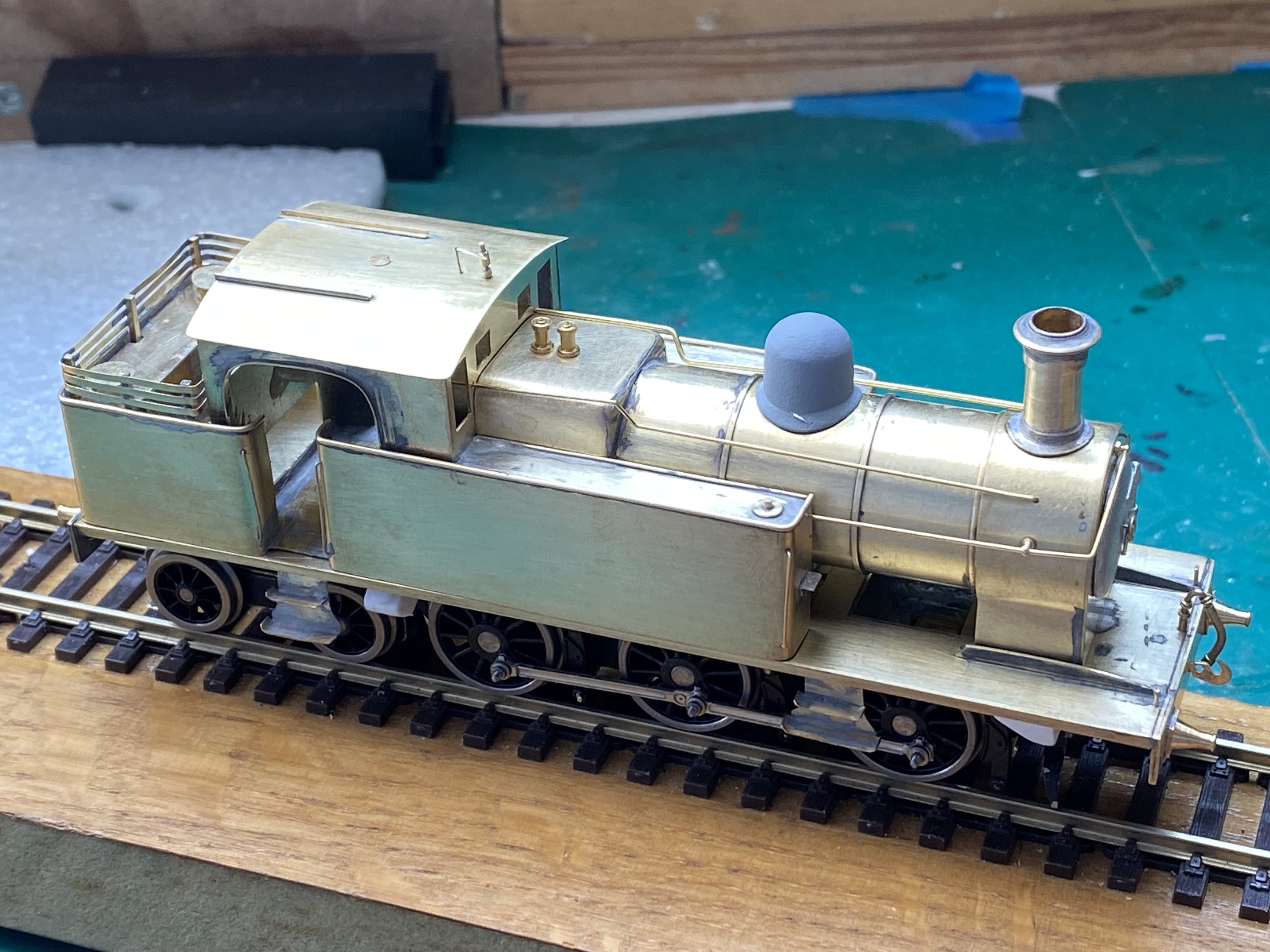
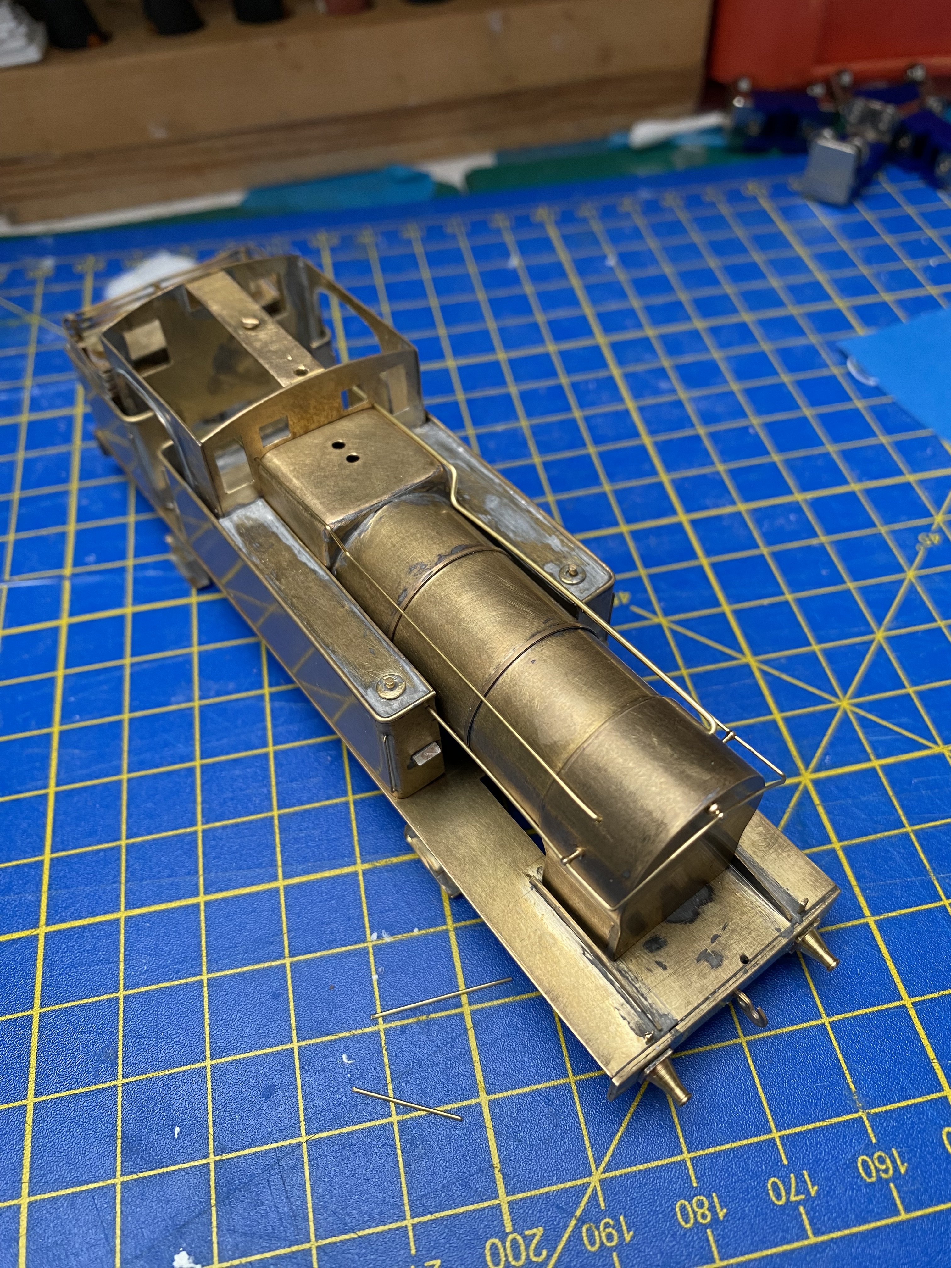
Last chance to see: No.29 in all its brassy brassiness before the great Halfords coverup. Or should that be the great Halfords show-up-all-the-flaws-I-didn't-notice? Bit of both I think. Onwards with rattle cans Alan
- 613 replies
-
- 13
-
-
-
Just wonderful! And imaginative use of 'found' materials. I like that very much!
-
More bad luck than you deserve David. Hang in there. It will definitely be worth it. The rolling stock looks great.
-
Ingenious. And lovely neat work too. If that was me trying that, the roof edges would remain unstuck but my fingers would be securely glued together and probably also to the roof Alan
-

Clogherhead - A GNR(I) Seaside Terminus
Tullygrainey replied to Patrick Davey's topic in Irish Model Layouts
Stop, Patrick! -
Beautiful work. Those models have real charm.
-
Ah David, what a thing to happen. That must’ve been hugely discouraging. I would say anguish doesn’t even begin to describe the feeling. You’ve made a great recovery though. Well done, both for fixing the damage and for recovering your composure so well. The big hammer stayed in the drawer Alan
-
Yes, I was surprised too Stephen. I didn’t expect to see it so soon
-
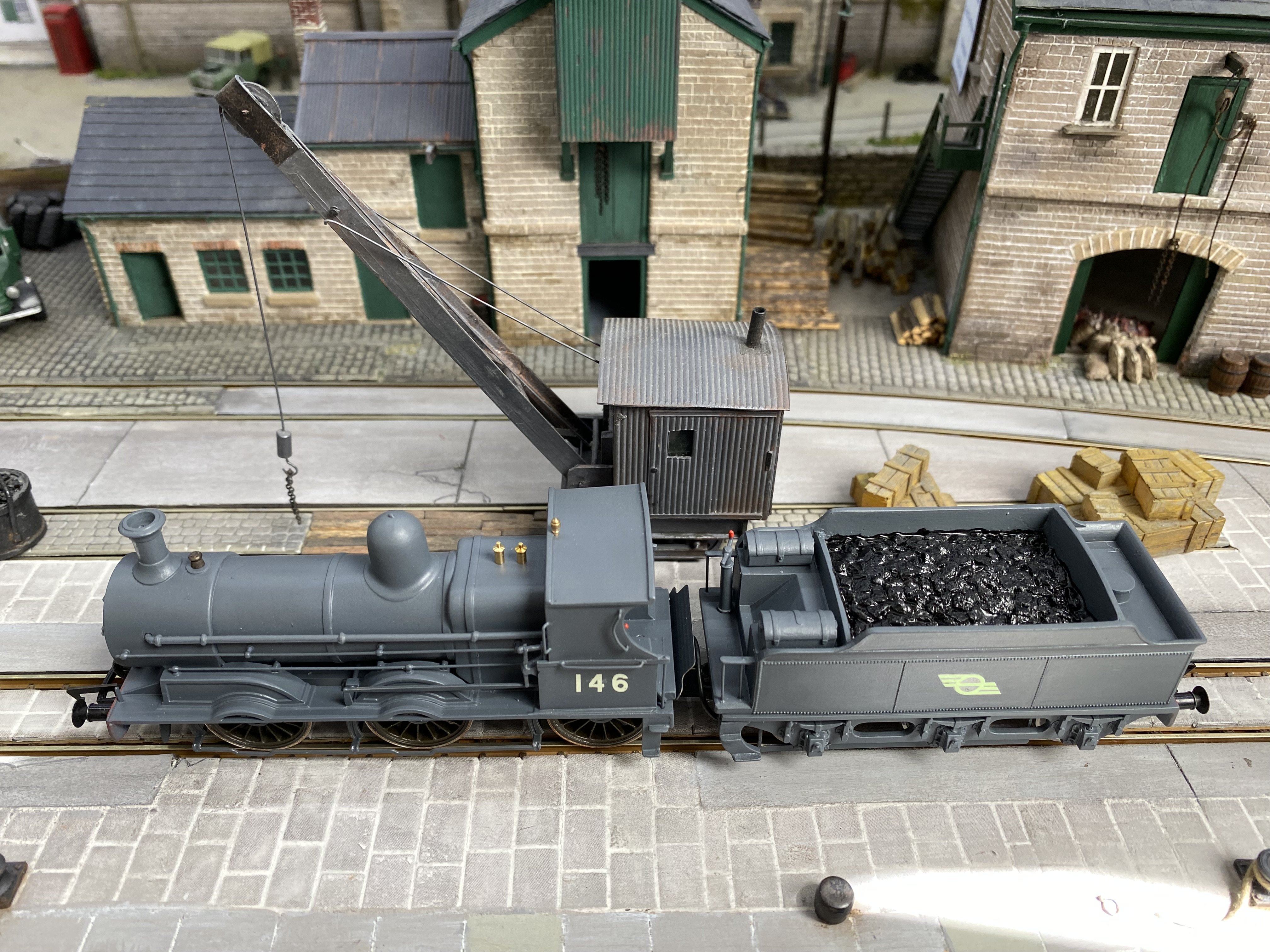
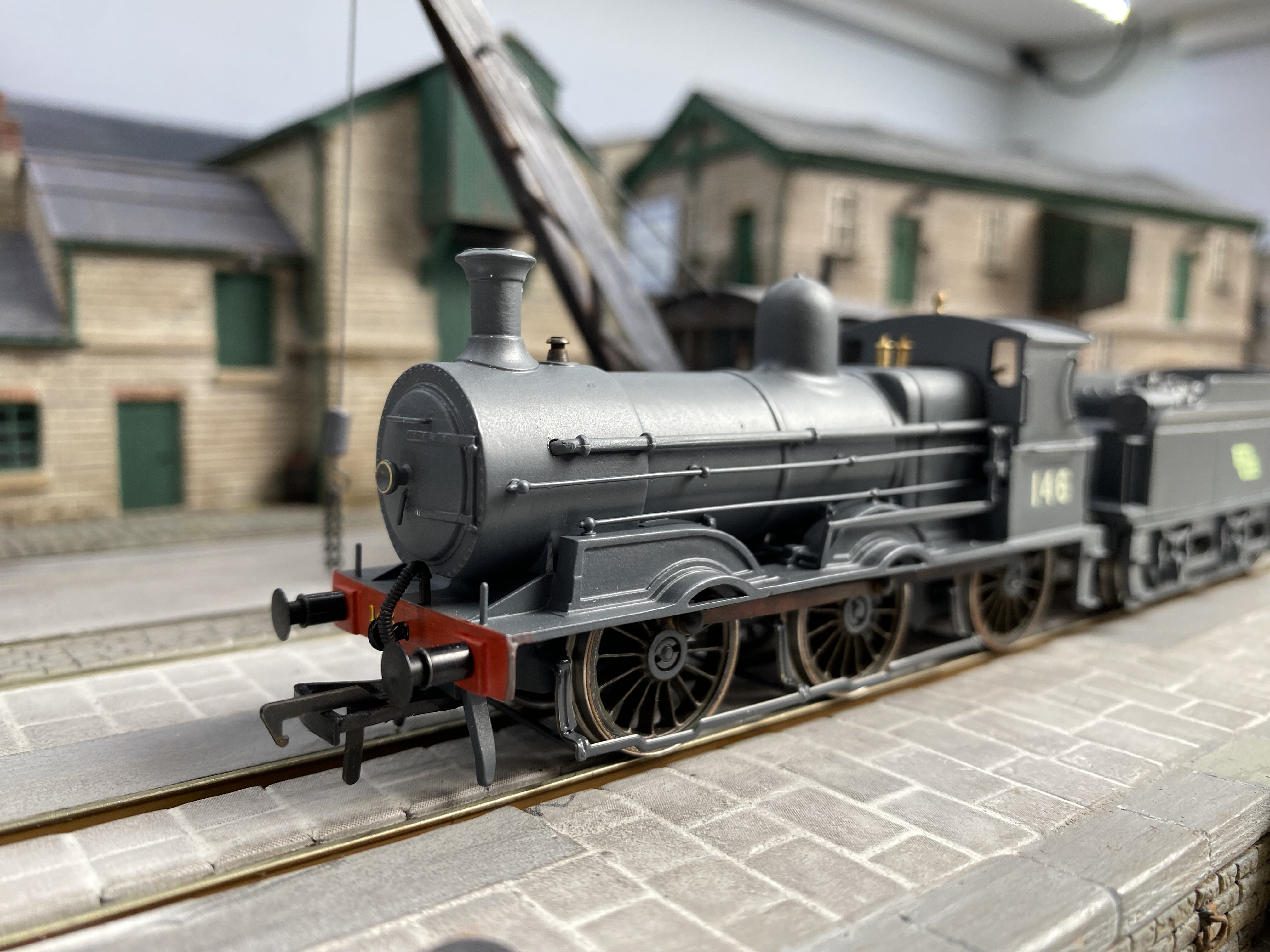
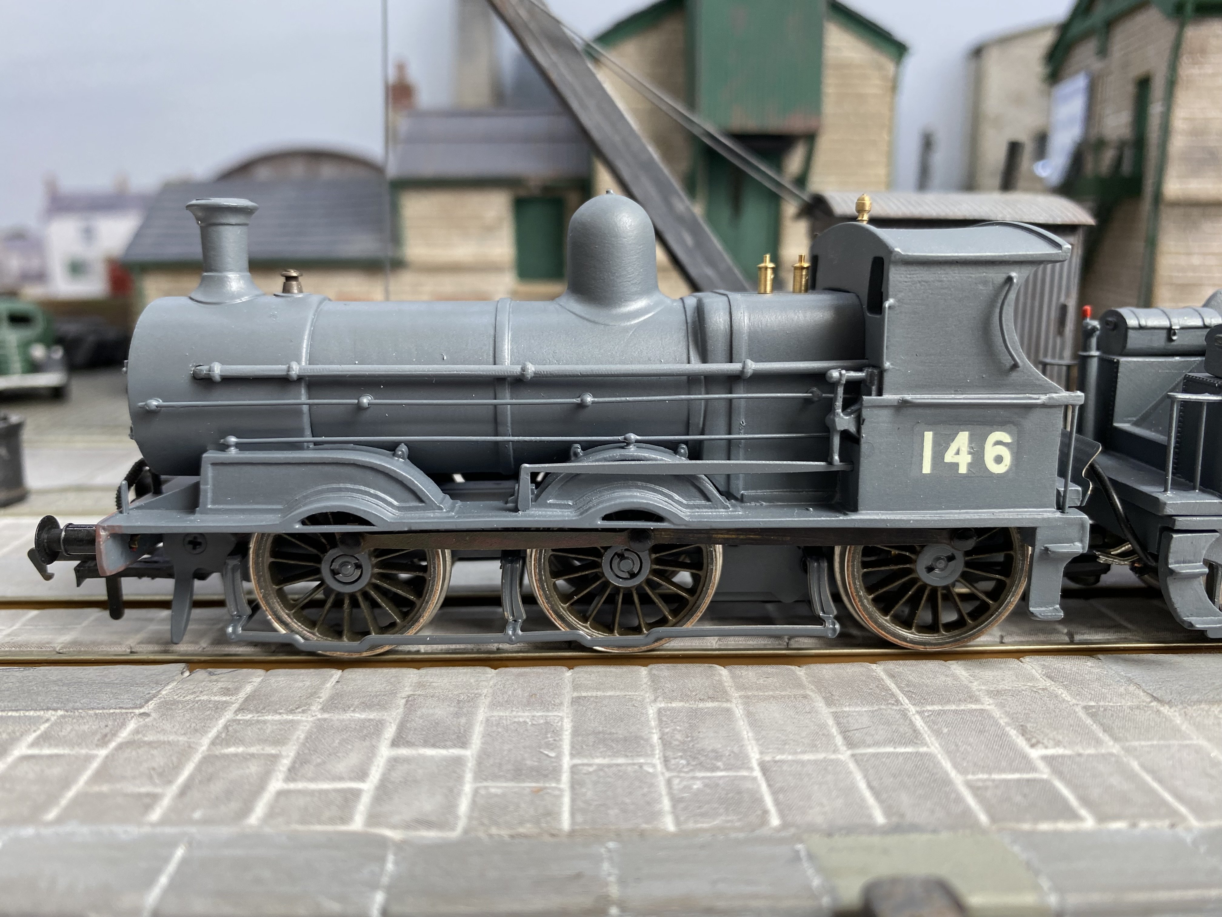
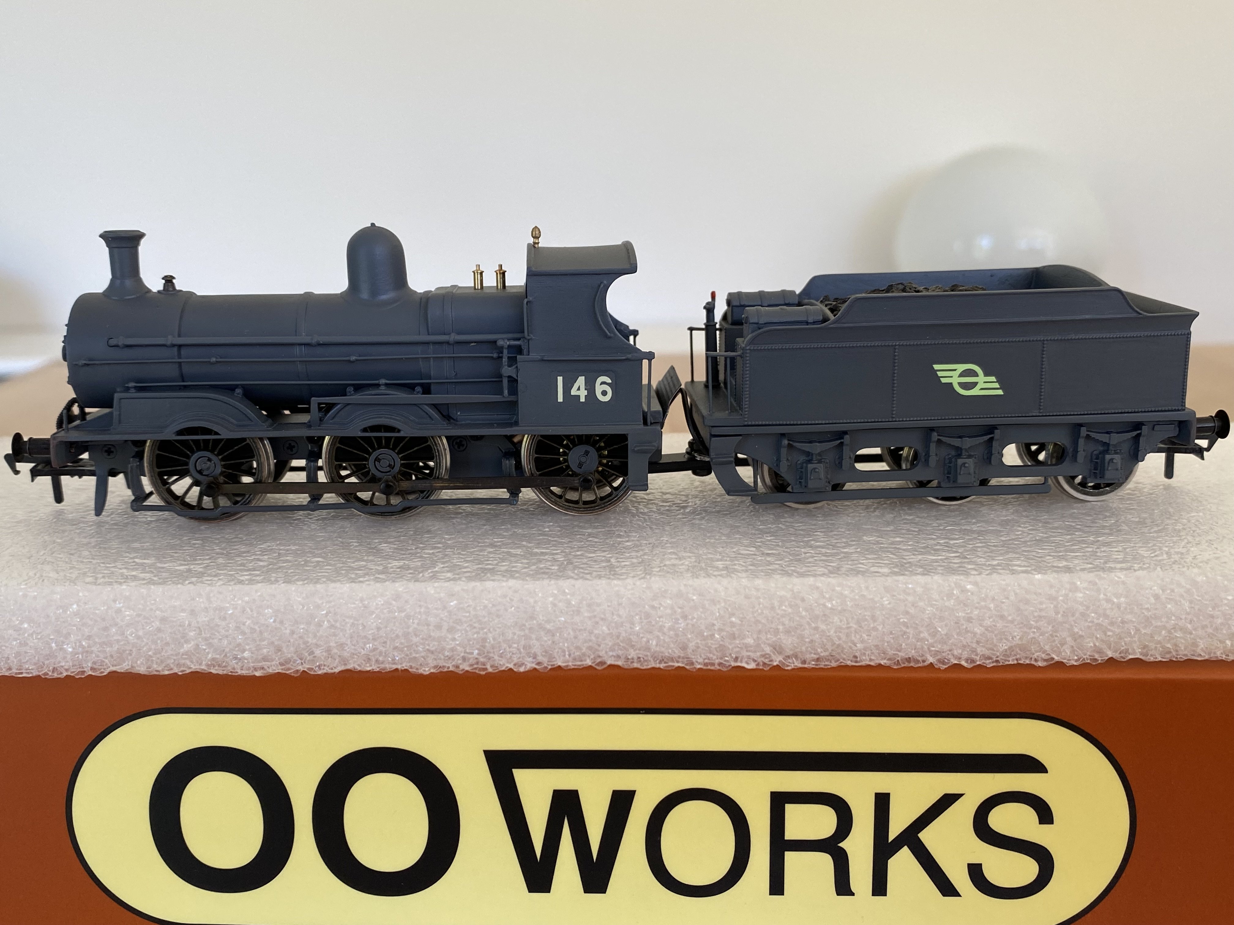
The A Class is beautiful and such a smooth runner. It just drifts along with no apparent means of propulsion. A revelation for me, weaned on hacked Hornby Pugs and cobbled together little 0-4-0s lurching and stalling over the points. I begin to see why there’s such enthusiasm for these models. Interesting how 146 looks black in your photos Patrick. It’s definitely grey. I checked.
-
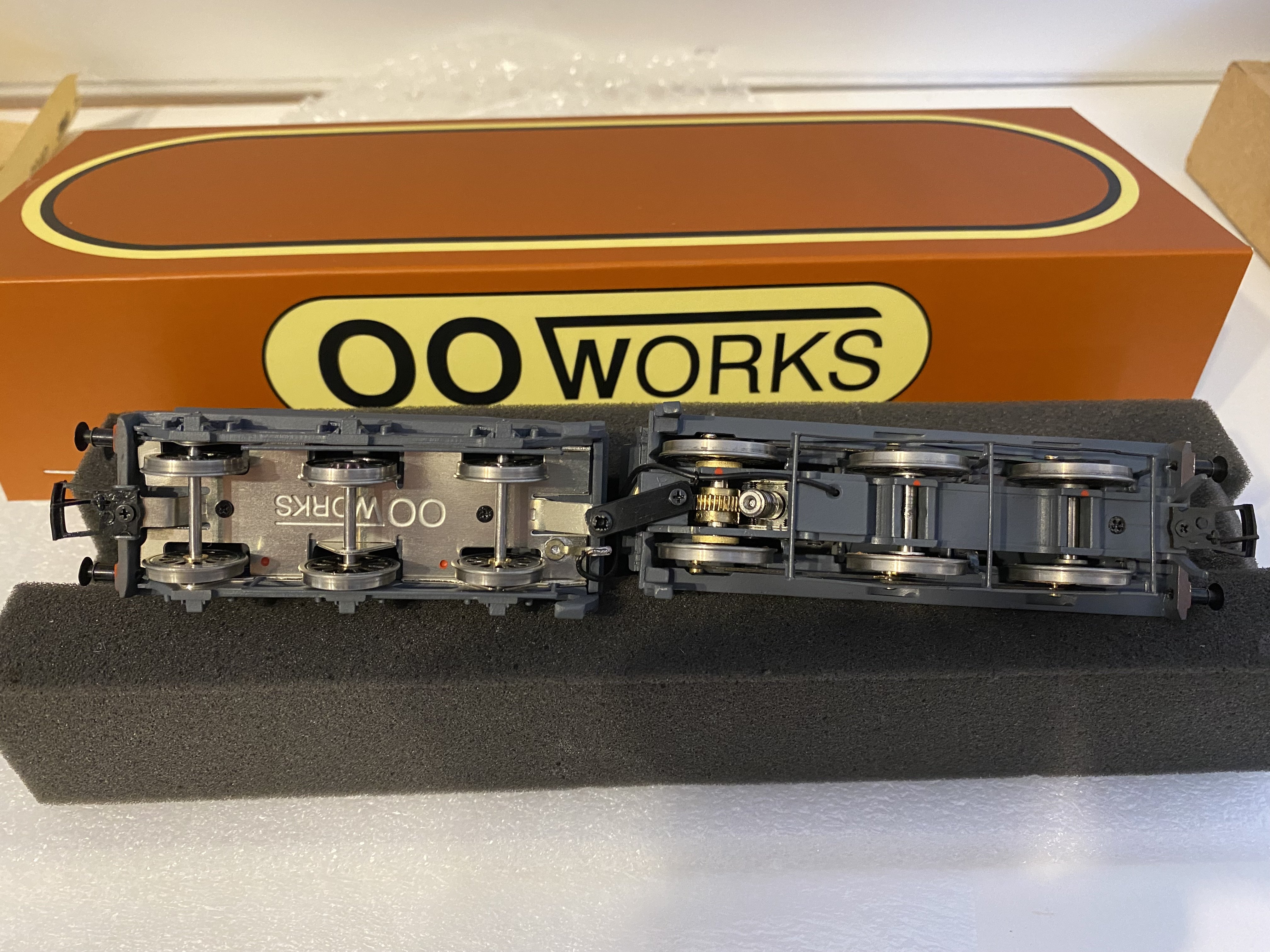
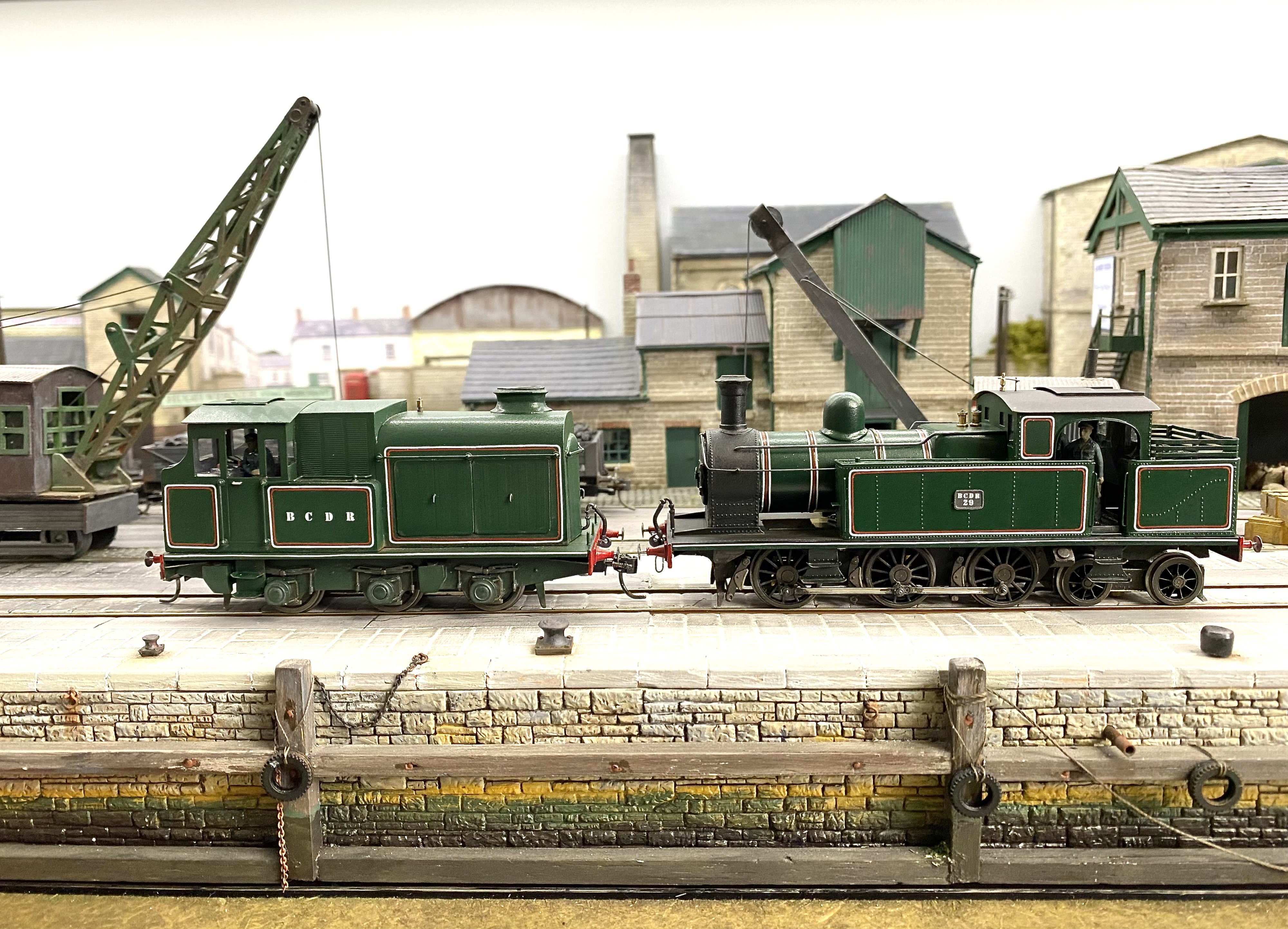
Certainly FS, here we are, fresh out of the box So far, I’m impressed with the build quality and finish. For a handmade model, it’s pretty remarkable. My example ran smoothly out of the box and once I’d taken a bit more care seating it properly on the track, it negotiated all the short radius points on Loughan Quay with a minimum of fuss. I think I’m going to have to build a layout for it. Or get Patrick Davey to invent a scenario which explains a J15 in BCDR territory. I have every confidence in him Alan
-
It is. Current batch. Delivered new this morning.
-
It was very early morning here at Loughan Quay in our quiet corner of County Down. Hardly anyone about. This came through. No-one else saw it. Afterwards, I wasn’t sure if I’d dreamed it. IMG_7680.mov
-
Thanks John. I can understand the difficulties in achieving that and I suspect making them by hand may be easier in some respects. It's a case of bend a bit, file a bit, fill a bit, bend it some more, start again. No maths or geometry involved!
-
Three attempts
-
Clogherhead - A GNR(I) Seaside Terminus
Tullygrainey replied to Patrick Davey's topic in Irish Model Layouts
Of course! Should have known. He did some work at Loughan Quay... -
Clogherhead - A GNR(I) Seaside Terminus
Tullygrainey replied to Patrick Davey's topic in Irish Model Layouts
Lovely work Patrick. Just taking in the artwork on the walls now I'm viewing this on a desktop. When I looked at it on my phone earlier, I took them for windows! Can't quite identify the artists though Alan -
Little Things Sent To Try Us Department: Bending handrails. And pipes. Trying to thread handrail knobs, I’m convinced each time that the little brat doesn’t have a hole in it. But they always do. Onwards with eyestrain, Alan
- 613 replies
-
- 12
-
-
-
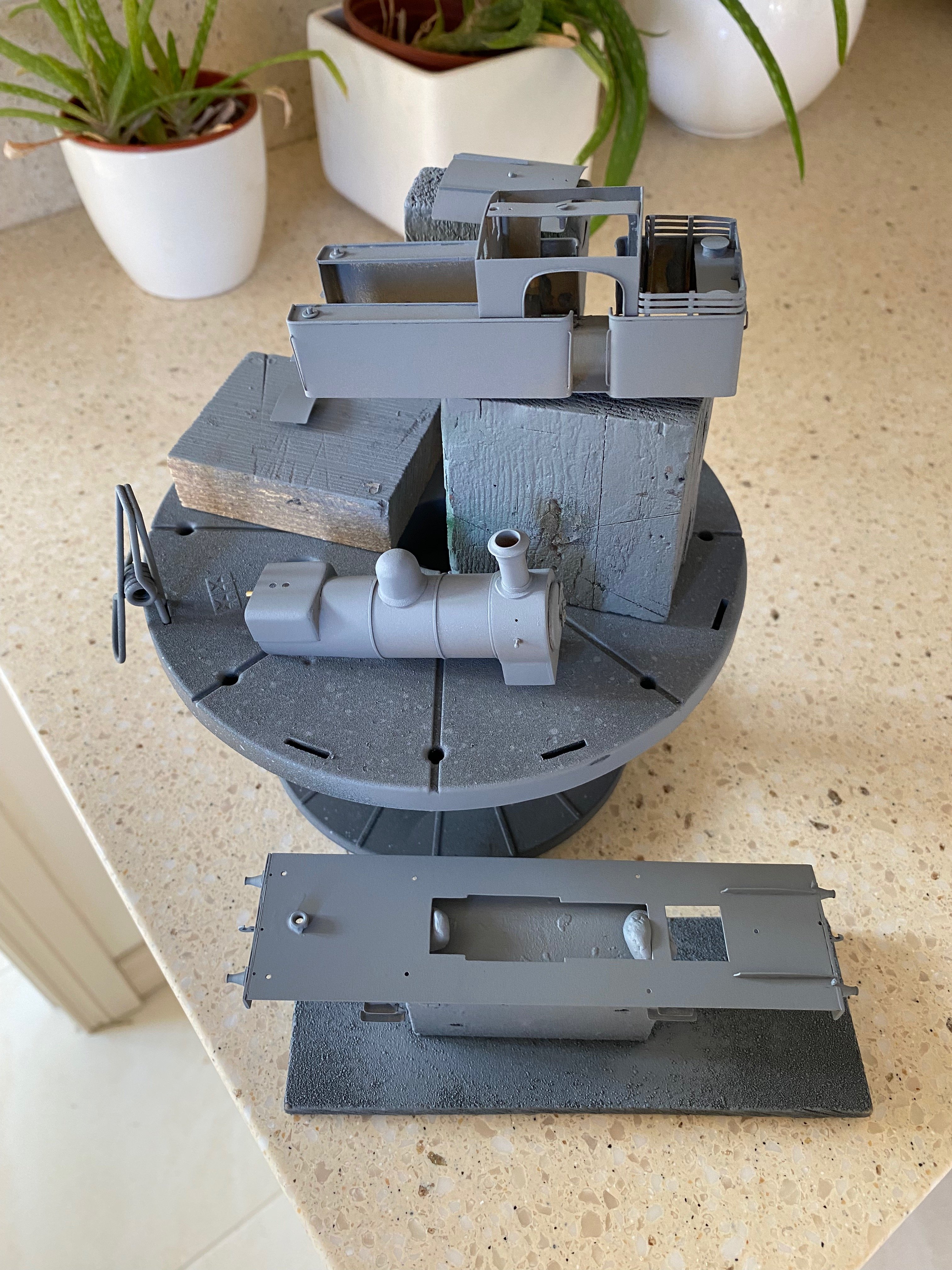
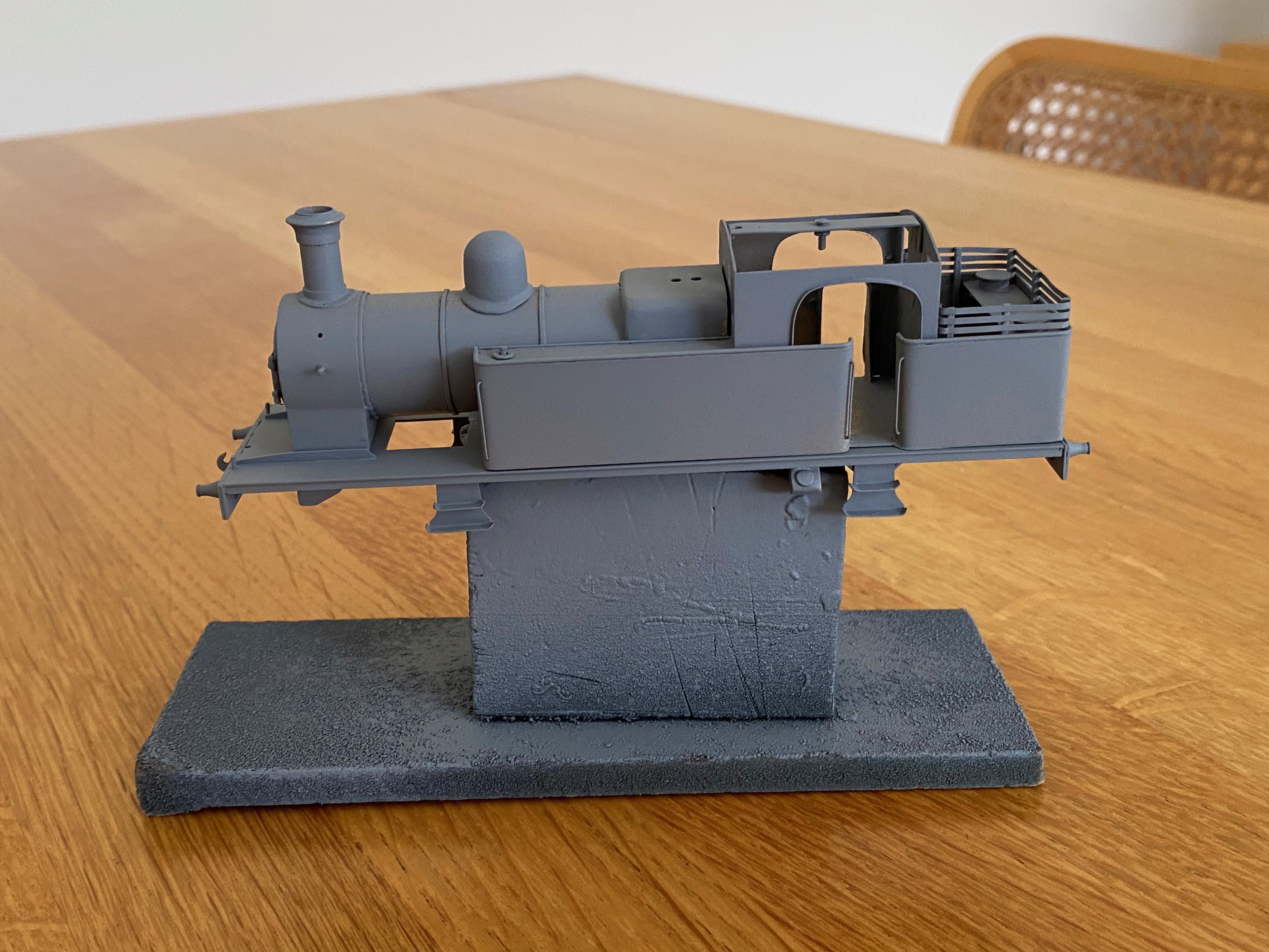
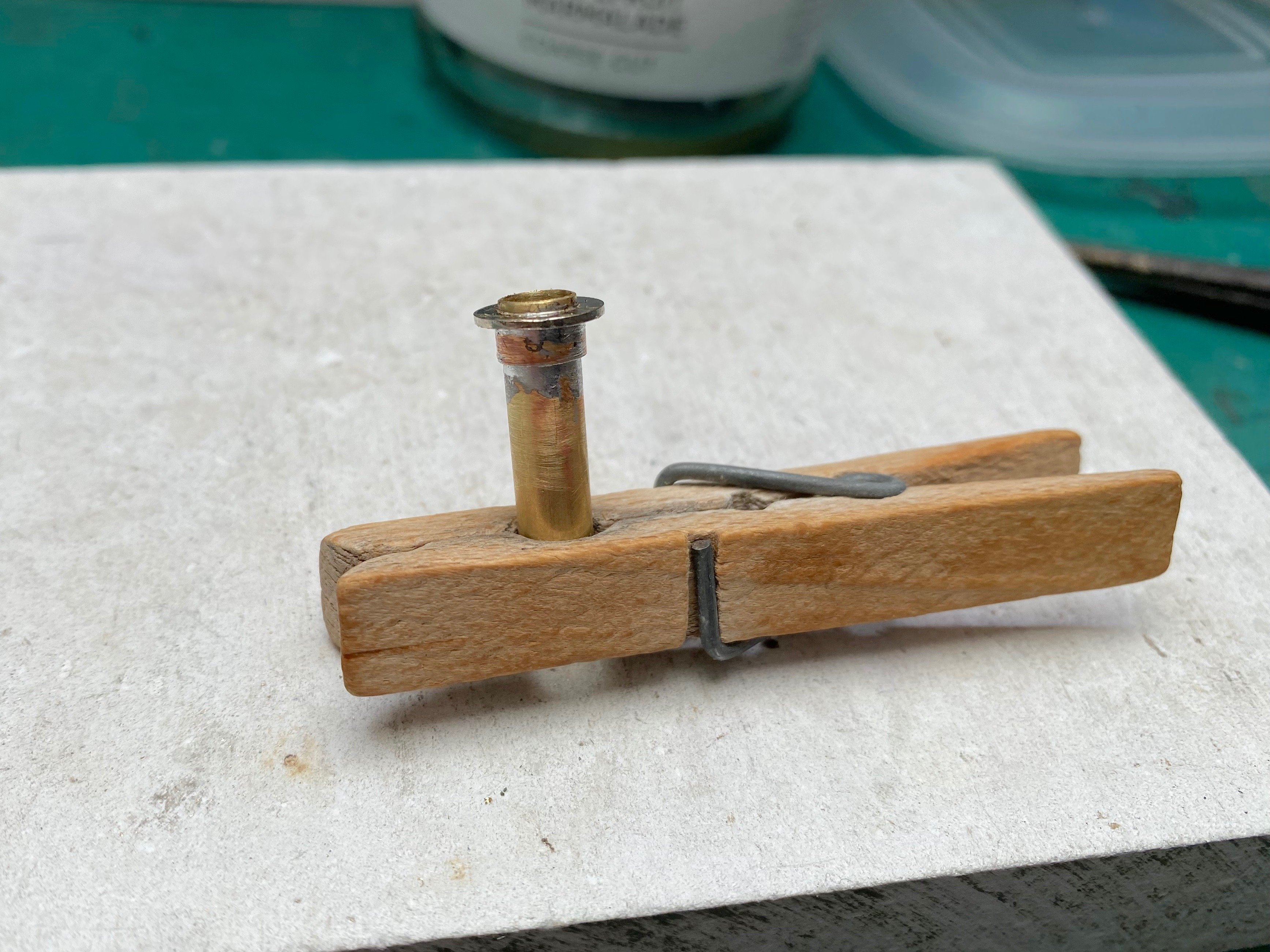
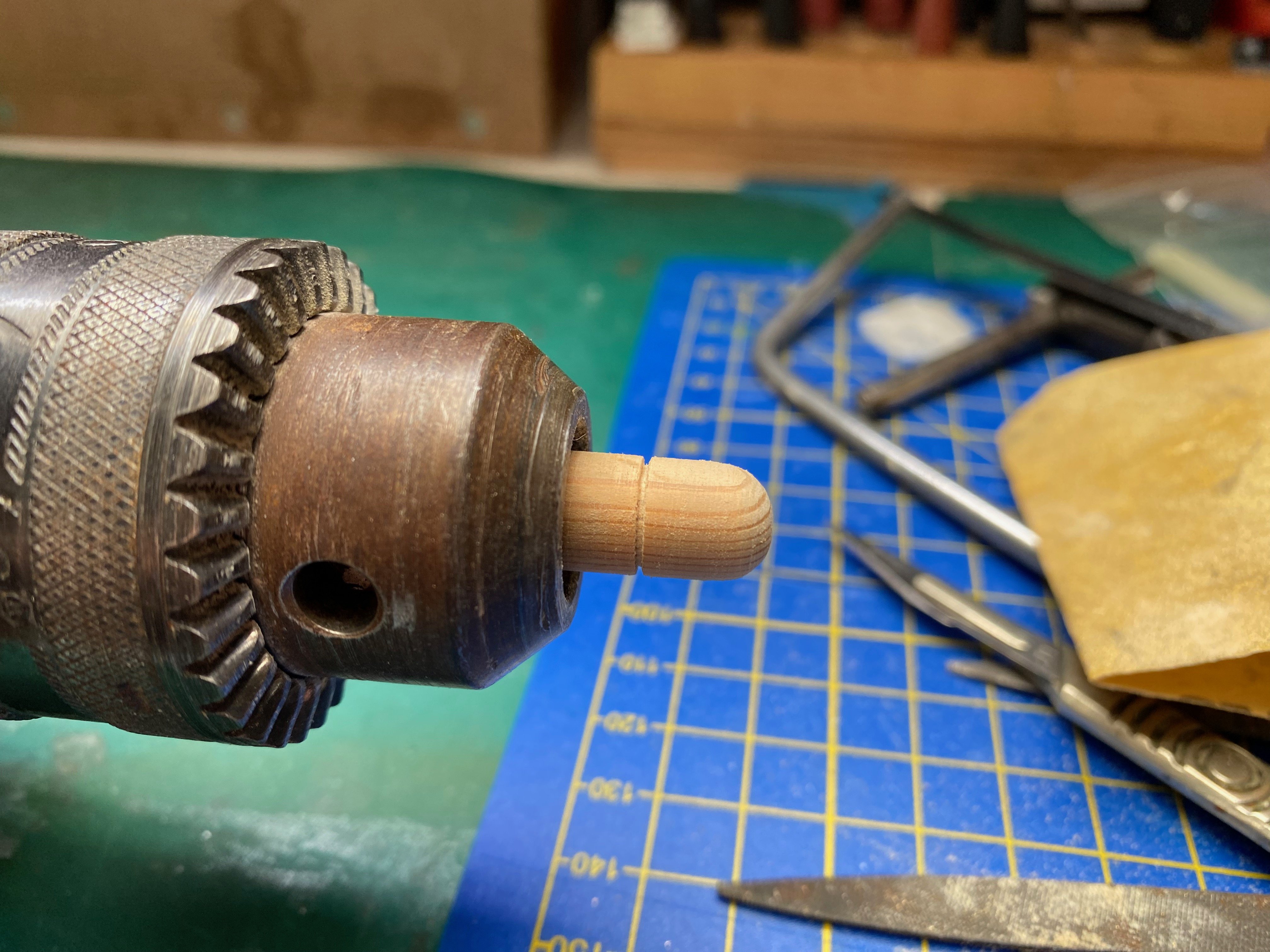
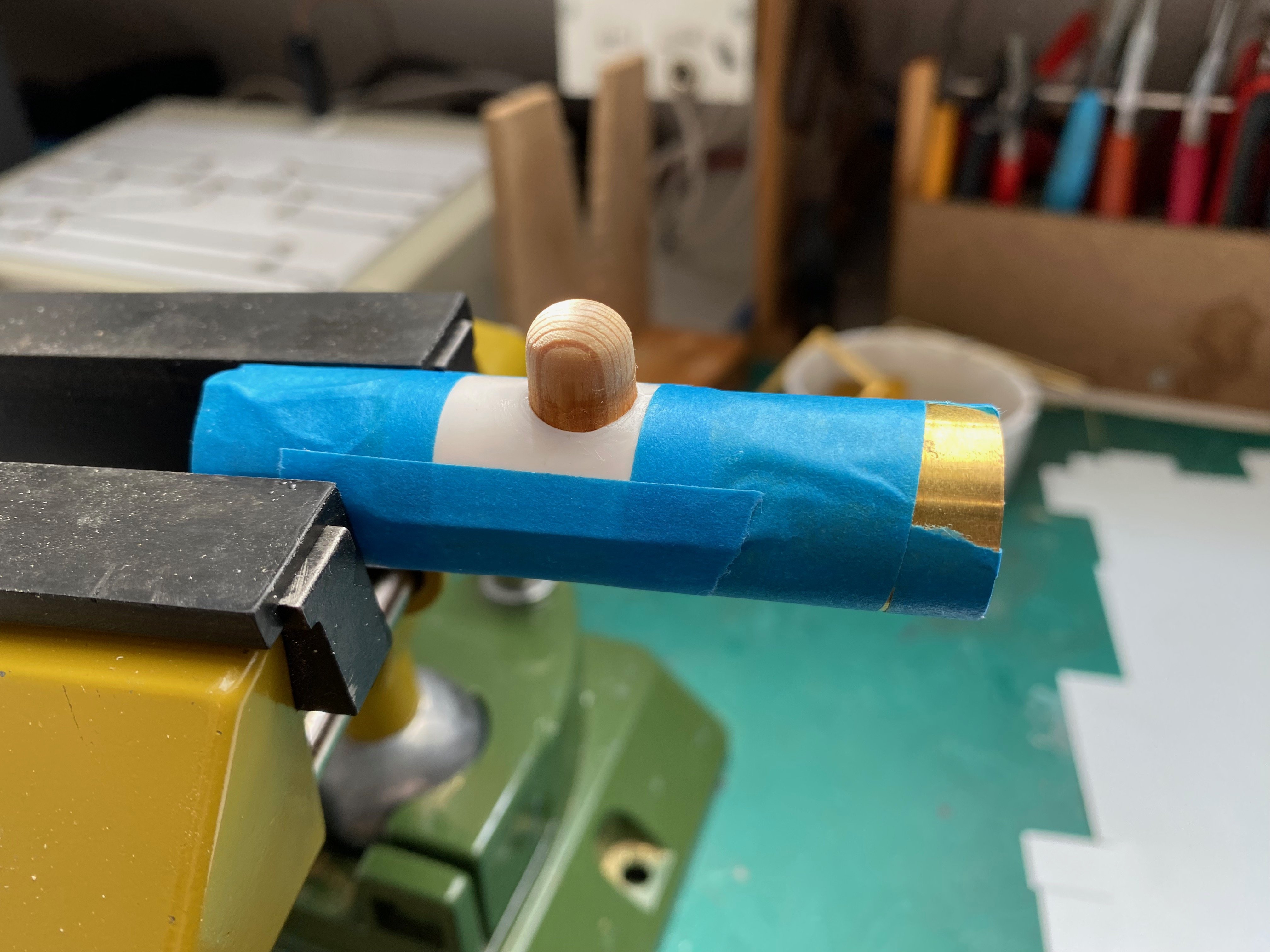
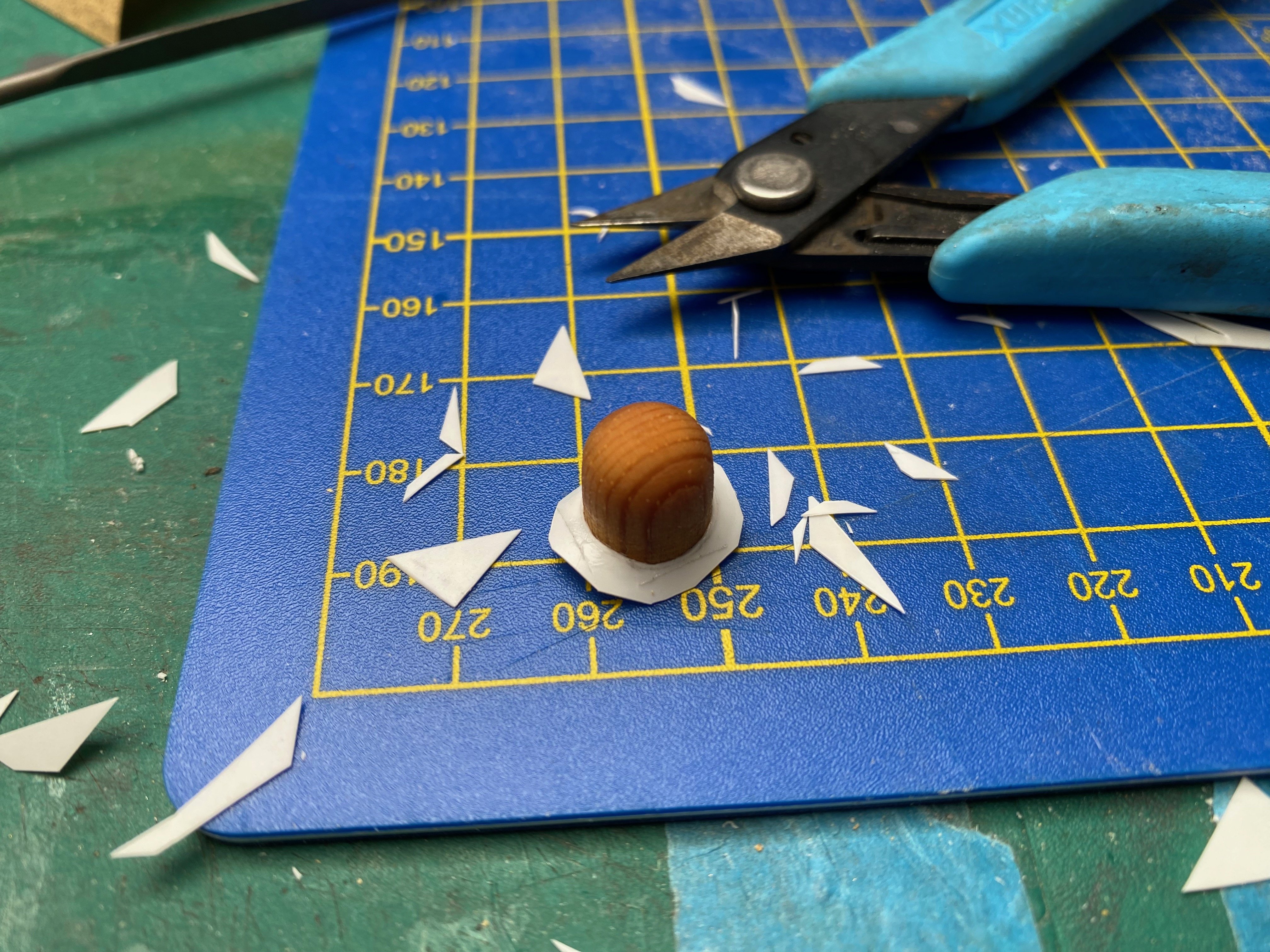
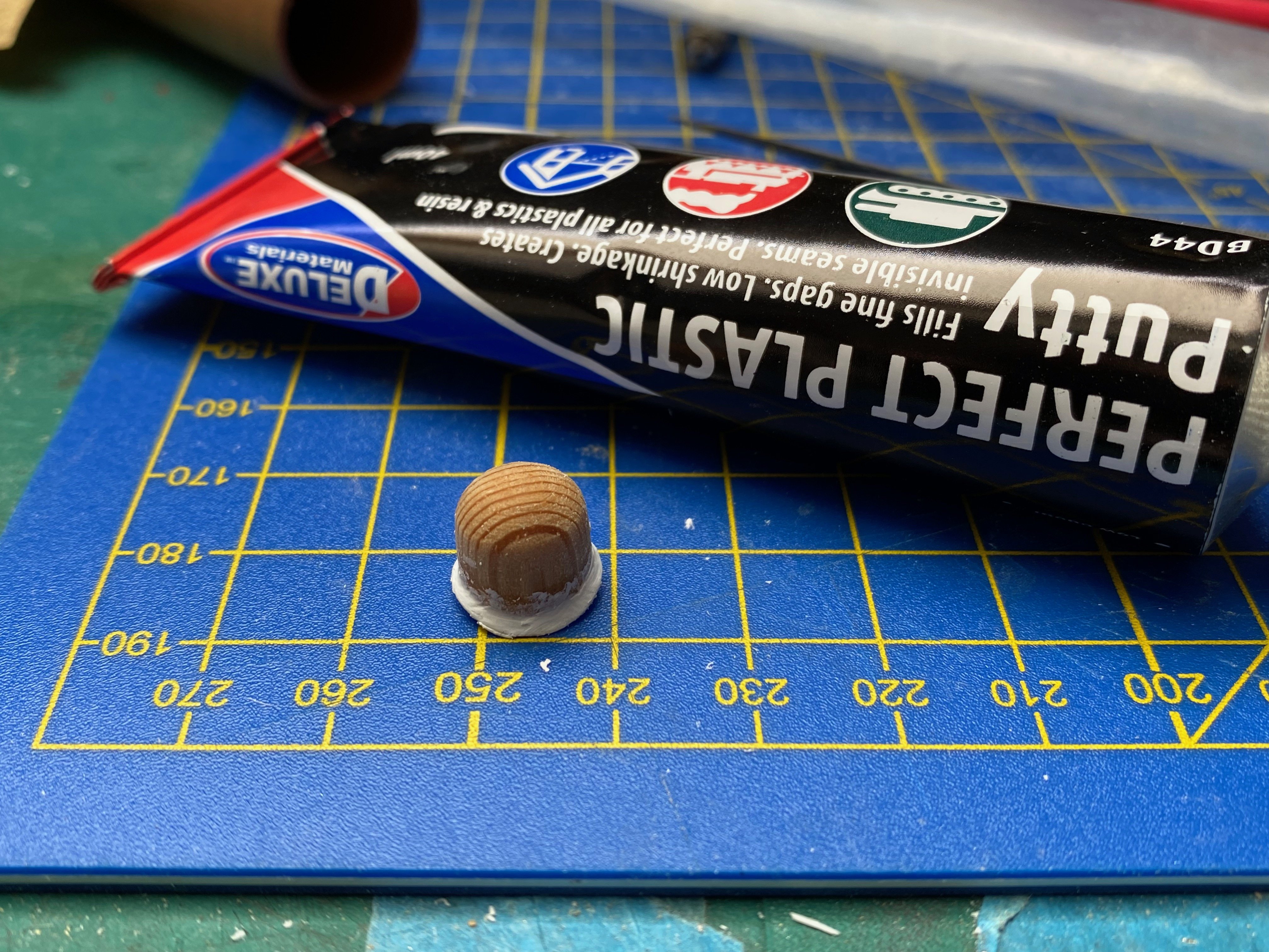
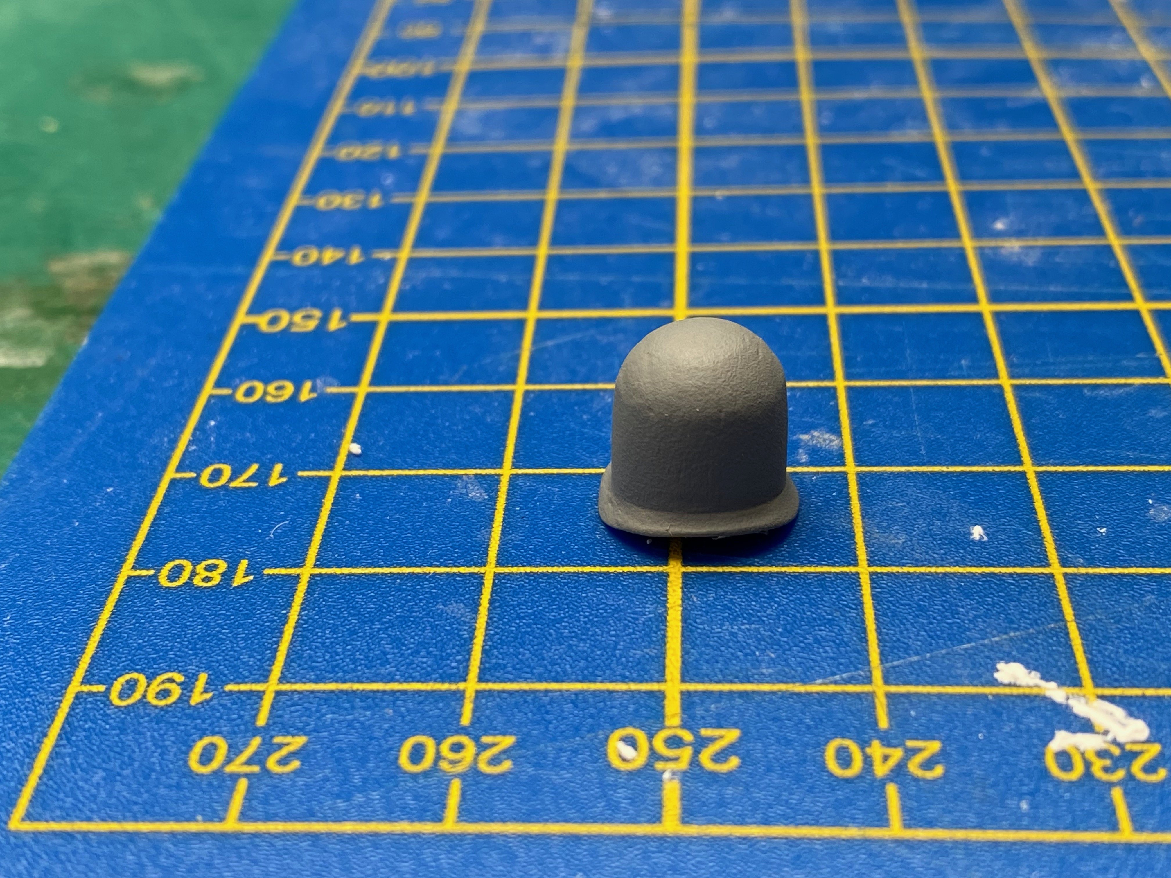
I've ordered up some chimney and dome castings, hoping some will be right for No 29. While waiting, I decided to have a go at making some. For the chimney, some bits of nested brass tube and a suitably sized washer were the raw materials. These were soldered together with 188 degree solder, then the rough shape built up with 145 degree solder and the final profile machined (and I use the term loosely) with files and emery while the thing rotated in the Black and Decker. Using higher temp solder to assemble the bits meant that the thing didn't fall apart while the lower temp stuff was puddled on. I learnt that the hard way - see failed project drawer. The bottom flange, in 10 thou brass, was the most difficult bit to do. The dome used the same process with different materials - wooden dowell, 0.5mm plastic sheet and filler. The dome was fitted tightly into a hole cut in a rectangle of plastic sheet and fixed with superglue. The sheet was taped round a suitable cylinder and the whole lot dunked in hot water, then cold, to induce a bit of a curve for the flange. We'll see how they compare with the commercial bits when they come. They may not get used but the process has been instructional. All those years watching Blue Peter weren't wasted Alan
- 613 replies
-
- 13
-
-
-

-
Tedious work indeed David but worth the effort as you say. It’s going to be good! I’m putting off applying the primer coat as long as possible on my present project and dreading what it’ll show up