Tullygrainey
-
Posts
949 -
Joined
-
Last visited
-
Days Won
56
Content Type
Profiles
Forums
Events
Gallery
Blogs
Store
Community Map
Everything posted by Tullygrainey
-
To clarify what I posted on 13.08, Smallbrook Studio does indeed sell individual parts from its ranges of kits. An email specifying your needs is all that's required to initiate an order. Alan
-
Beautiful! The shot of 170 on the bridge with her reflection in the water is just perfect.
-
You're certainly having a torrid time with that crane one way and another David. You seem to have been very unlucky with the shuttle unit. Very frustrating. It's a great model and deserves to be seen moving so I hope you can get it sorted before too much longer. Hang in there!
-
What a wonderful machine! And a beautiful model too.
-
Thanks David. I'd completely forgotten about Smallbrook, despite having this sitting at my elbow every time I use this computer That chimney looks pretty close to what I need. I've had a look at the Smallbrook website and it seems they may have discontinued selling single bits from their kits. I'll try an email anyway and see what transpires. Some of the Laurie Griffin chimneys come close but the problem is likely to be size as much as shape. Peckett is a 7mm/foot model but its dimensions are closer to a 4mm model. The original really is tiny. I'm not familiar with ScaleFactor and couldn't find anything on-line. Do you have a weblink for them? Regards Alan

-
Thanks J-Mo. That’s probably the best solution but I don’t have the tools or skills to do that yet
-
Thank you very much. It’s a bit of a fudge but I think it will look ok once it’s in place
-
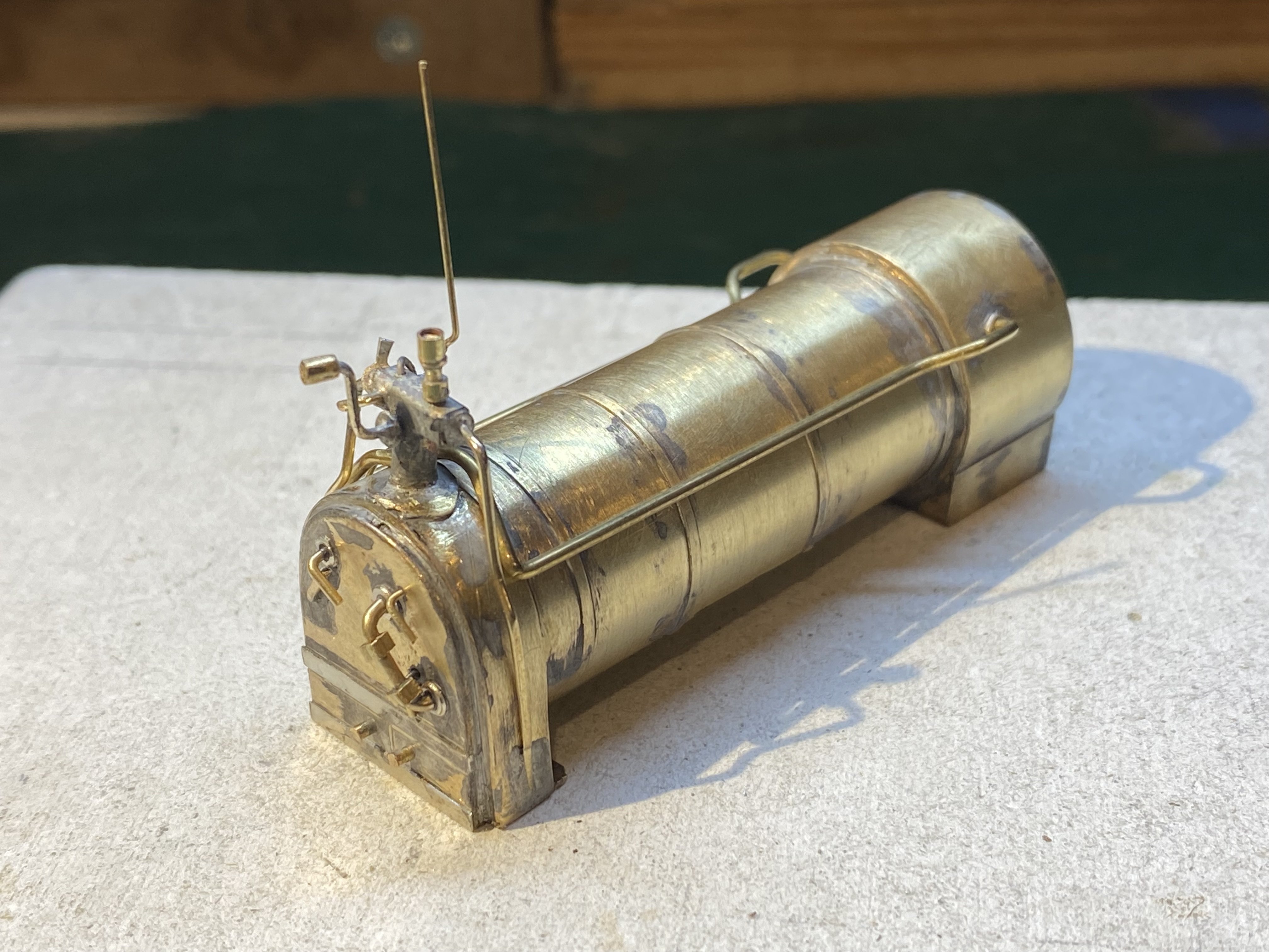
Some small Peckettbits - cab controls and a pair of tank fillers. The boiler also gained a few fittings this week. Don't look too closely at all that plumbing. It doesn't really make a lot of sense but I was aiming for something that looks reasonably steam-enginey. By the time it's buried inside the cab and the driver gets in there with his shovel, flask, lunch tin and paper, it may be hard to see anyway. With a bit of luck. The chimney has so far defied me. It's tall and slim and some nested brass tube would have done the job except that it tapers from top to bottom. Mine may well not do that. Alan
- 641 replies
-
- 14
-

-

-
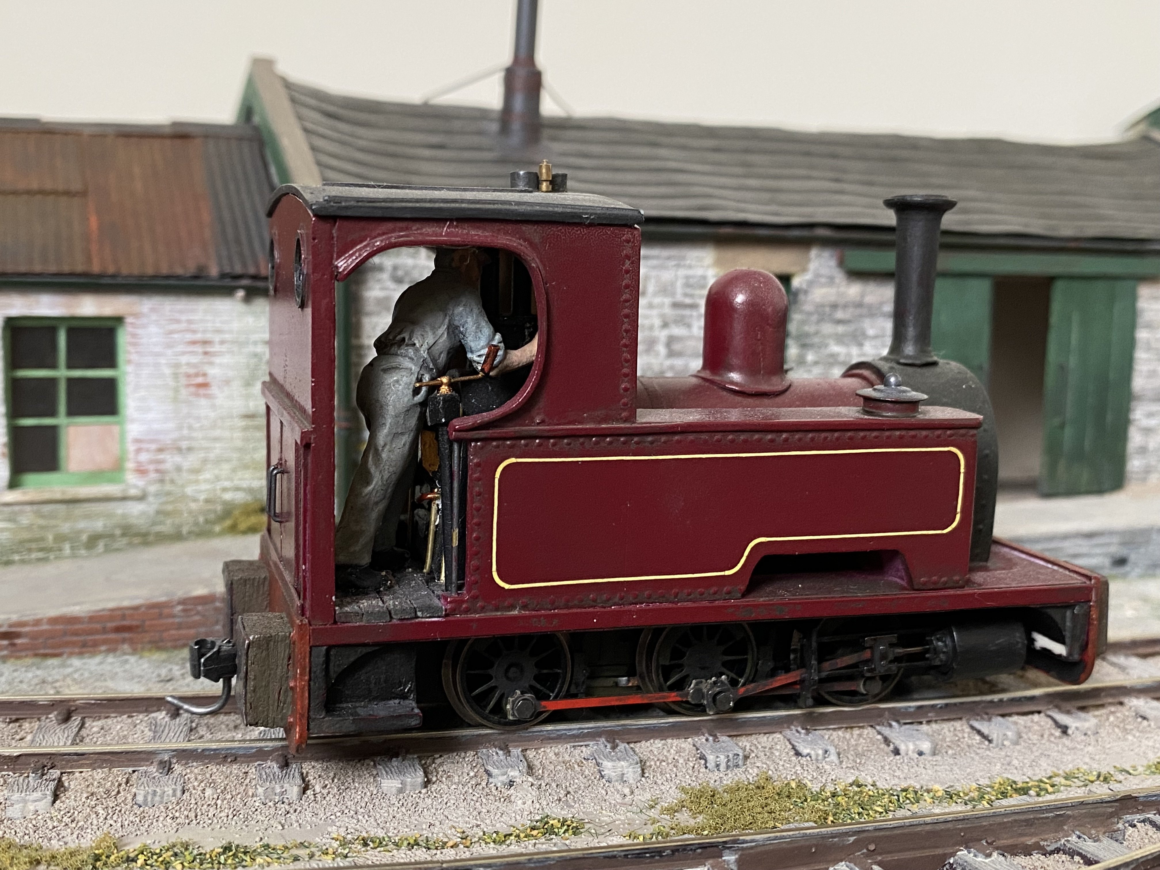
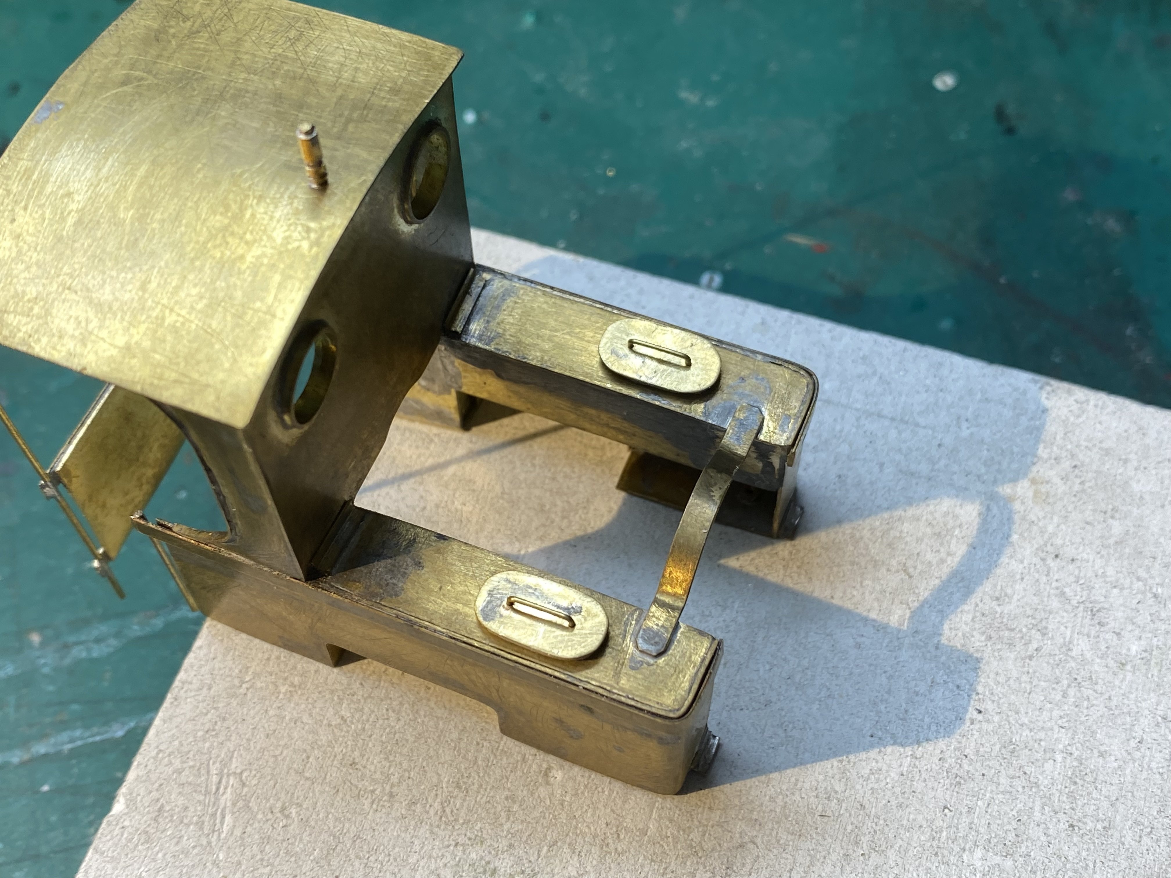
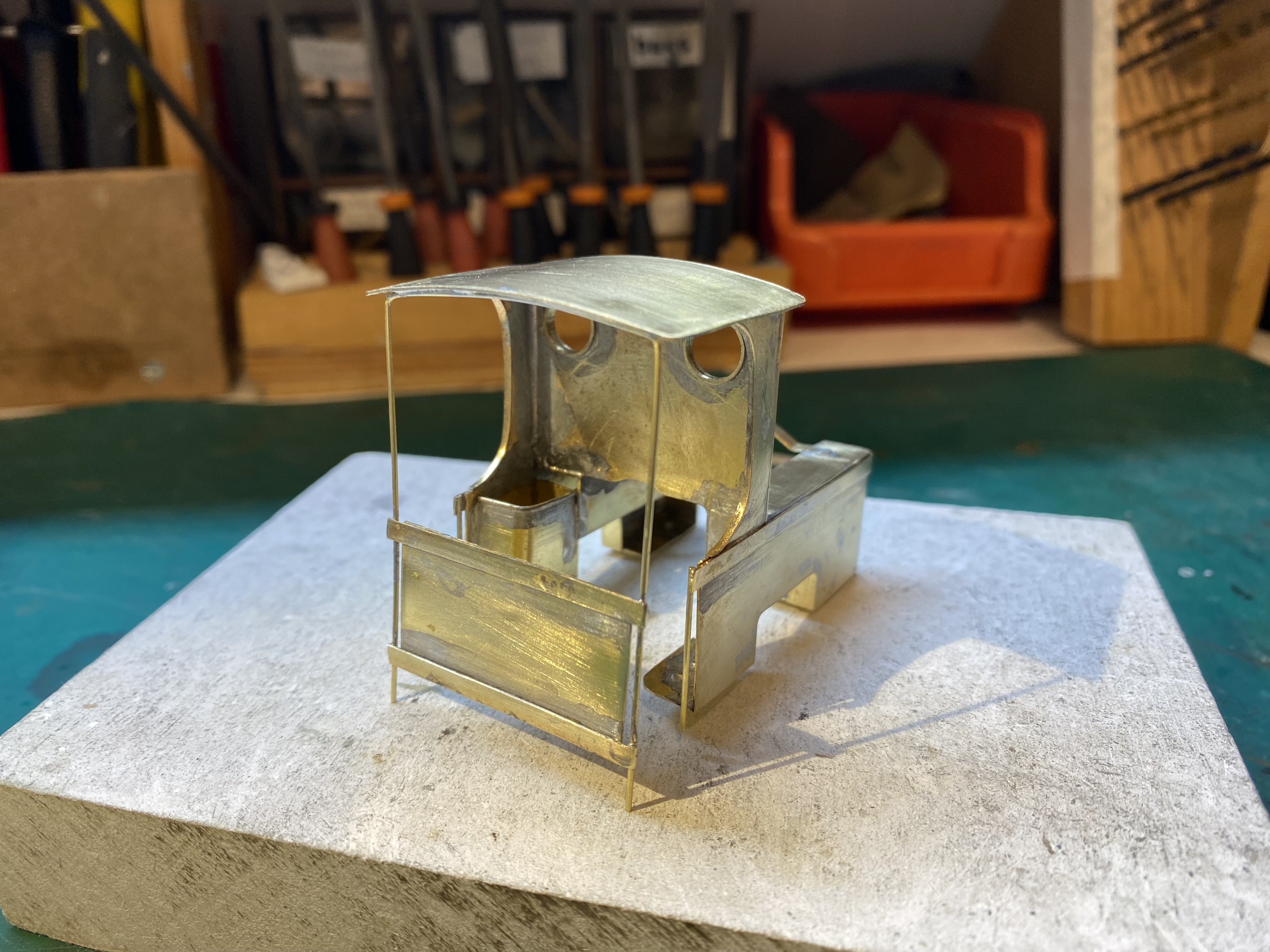
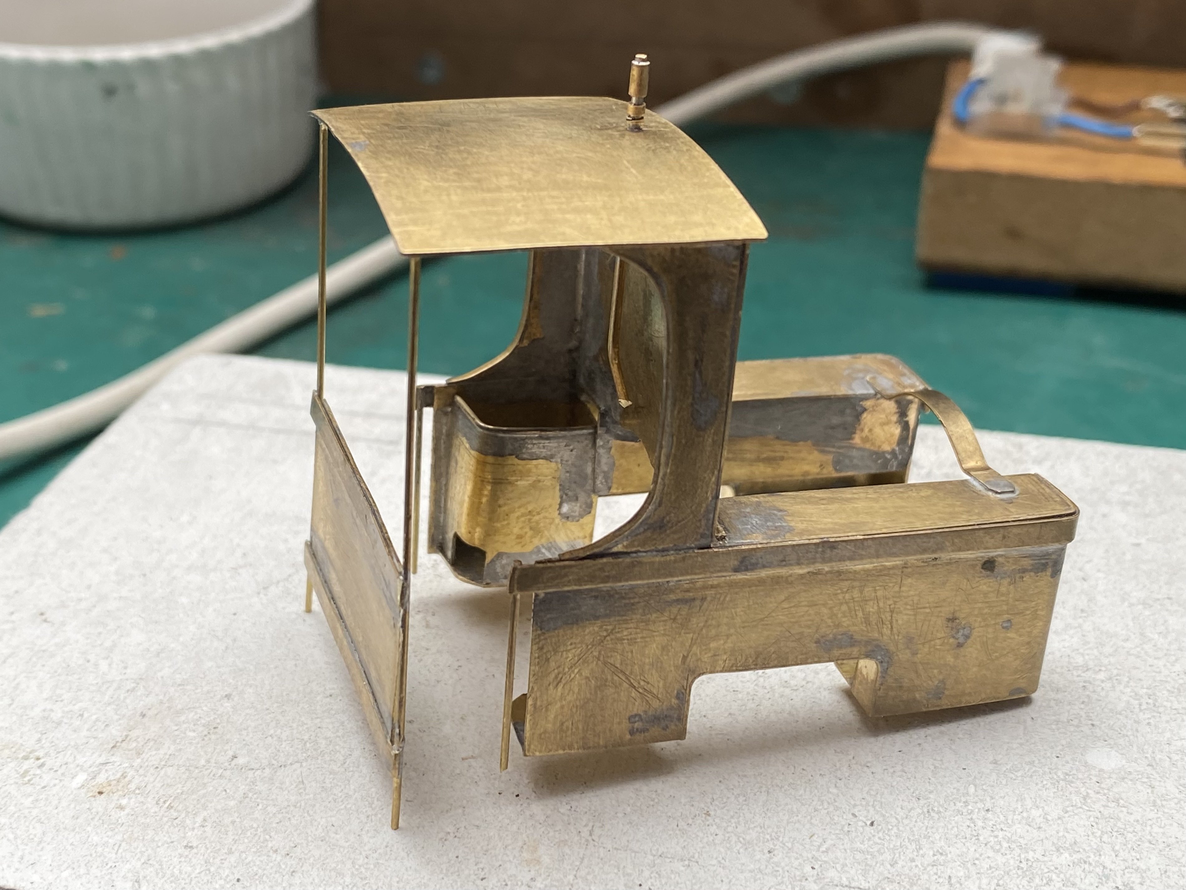
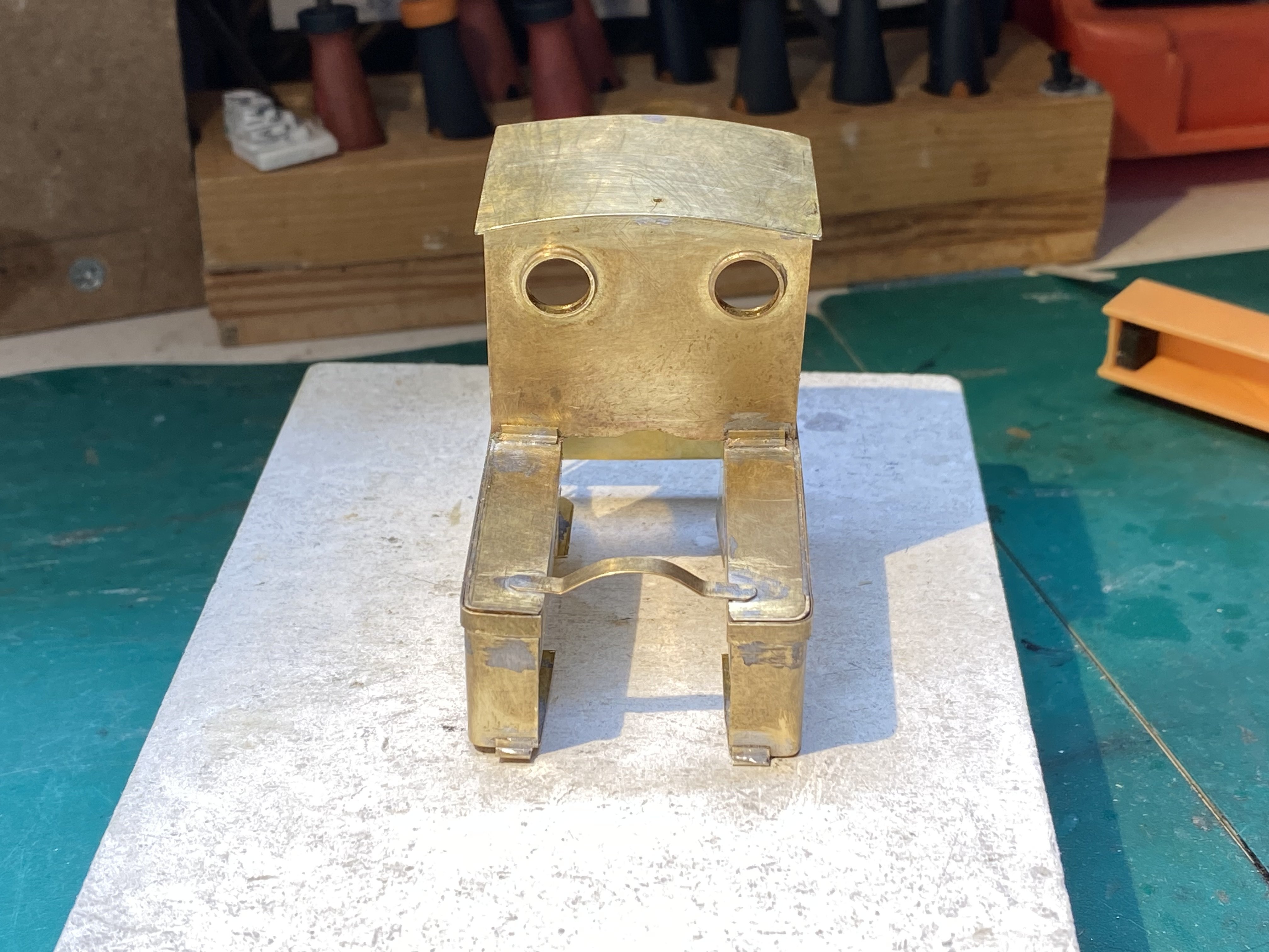
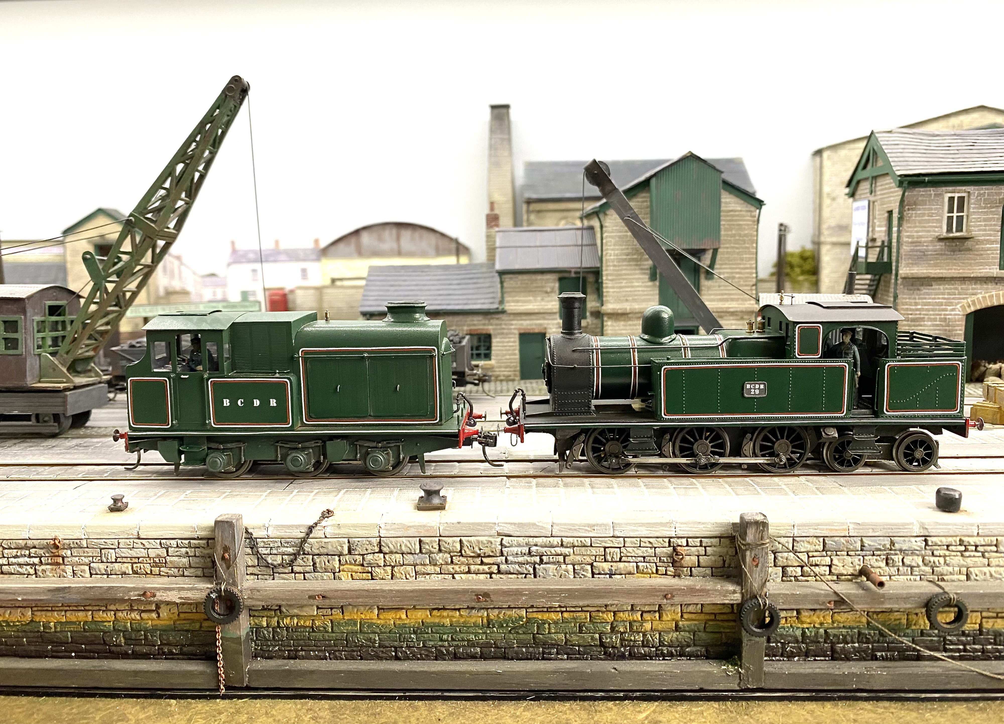
Wet Sunday so more indoor activity down the Peckett Works. The cab is no longer defying gravity at the back. The job was quite tricky - it felt as if I was soldering fresh air to fresh air a lot of the time. The various handrails slot into holes drilled in the running plate and it's quite strong once it's bolted down. Peckett now has a bunker too though it hardly qualifies as one. More coal scuttle than coal bunker. The coal it can hold might have got a BCDR Baltic as far as the end of the platform at Queen's Quay. Need to think about cobbling together a backhead for this one. No hiding place in such an open cab Alan
-
Fascinating stuff John. So much skill and ingenuity. Reading Derek Naylor's account of making coupling rods from Dinky hair curlers, chassis frames from curtain rail and bodywork from Oxo tins, I'm reminded how fortunate we are now in terms of available materials and components. Alan
-
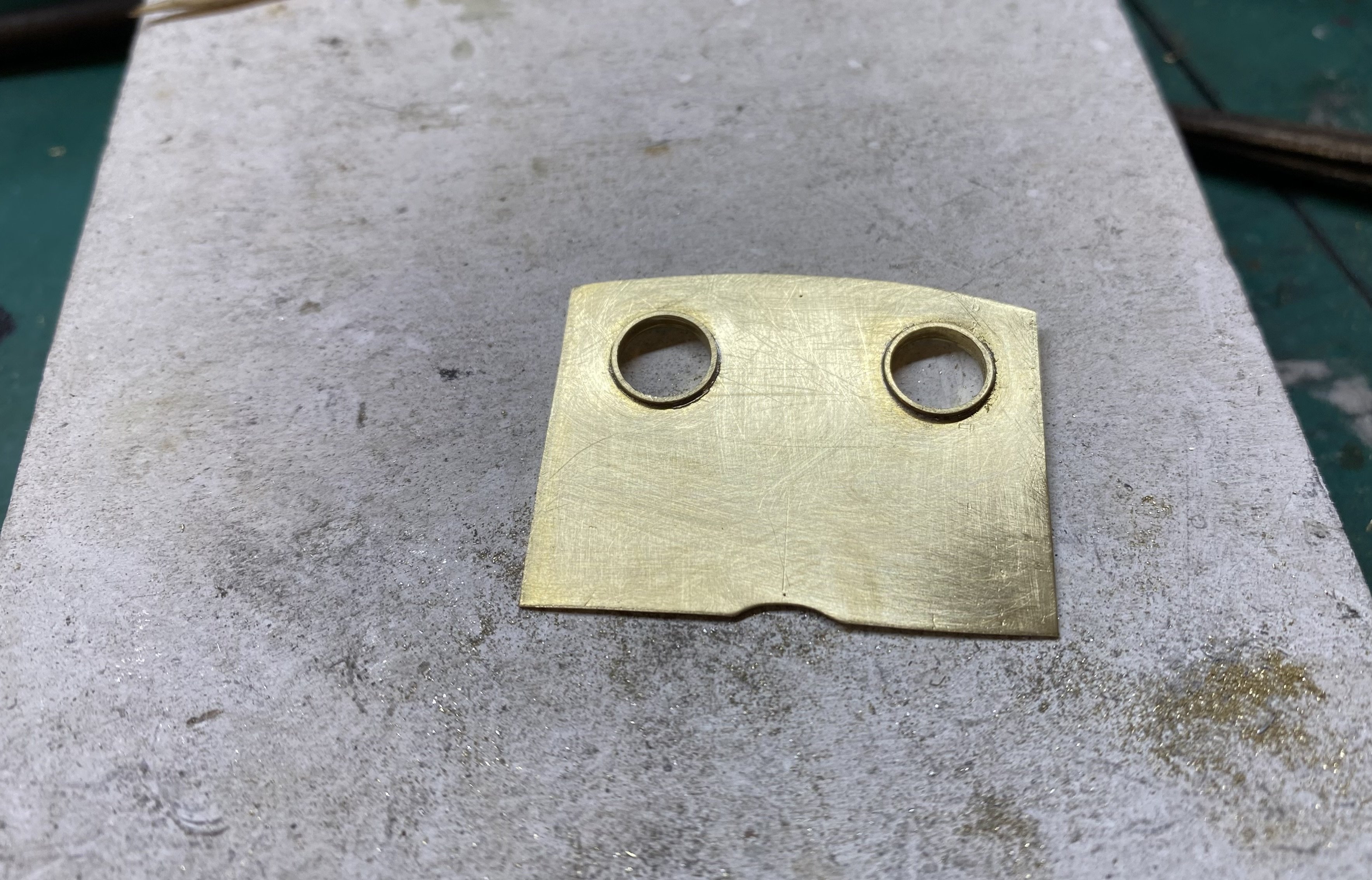
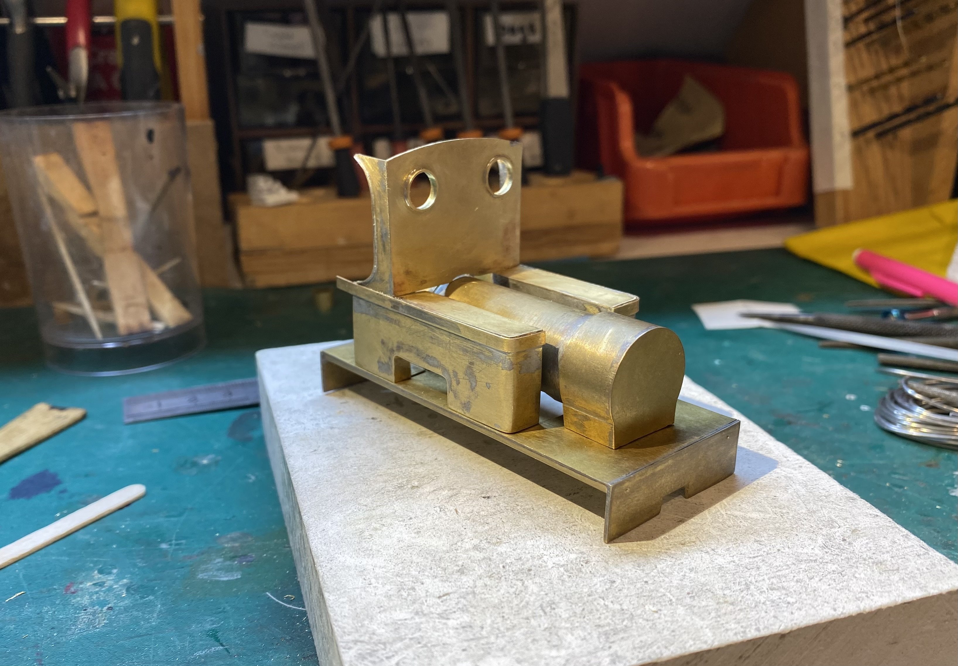
A nice simple shape for the Peckett's cab front with window frames made using slices of brass tube from a bag of assorted offcuts I bought at the Bangor show a while ago. With the boiler and tanks bolted to the running plate, the cab front could be soldered in and trimmed to size. A brace across the tanks and the roof on. It's beginning to have a bit of structural strength at last. It'a an odd little beast but the further I get with it the more I like it Pecketting away merrily Alan
- 641 replies
-
- 14
-
-
-
A shame about your rogue shuttle unit David. That’s v frustrating but all being well the replacement will do the job. All looking good on NPQ. That’s a nice compact little control panel.
-

Clogherhead - A GNR(I) Seaside Terminus
Tullygrainey replied to Patrick Davey's topic in Irish Model Layouts
STOP! I’m developing an allergic reaction to puns -
Clogherhead - A GNR(I) Seaside Terminus
Tullygrainey replied to Patrick Davey's topic in Irish Model Layouts
Ok truce! I’m sorry I asked about the gulls -
Clogherhead - A GNR(I) Seaside Terminus
Tullygrainey replied to Patrick Davey's topic in Irish Model Layouts
And hens again- those chooks you mentioned (I’ll see myself out) -
Clogherhead - A GNR(I) Seaside Terminus
Tullygrainey replied to Patrick Davey's topic in Irish Model Layouts
Very fine. I liked the way A30 just snuck up there! Amazing how the addition of one building makes it begin to feel like a place. Coming together nicely Patrick. Have the seagulls been delivered yet? -
Pecketttanks
- 641 replies
-
- 10
-
-
Do you ever sleep Darius? Or have you got a time machine that lets you do each day a couple of times? Very fine work. Alan
-
Clogherhead - A GNR(I) Seaside Terminus
Tullygrainey replied to Patrick Davey's topic in Irish Model Layouts
Music to the ears of any diesel fan. And maybe a few steam buffs too? Any plans for a quartet piece Patrick? -
Boat building! Now that would be a new challenge. Could be ok though. No outside cylinders...
-
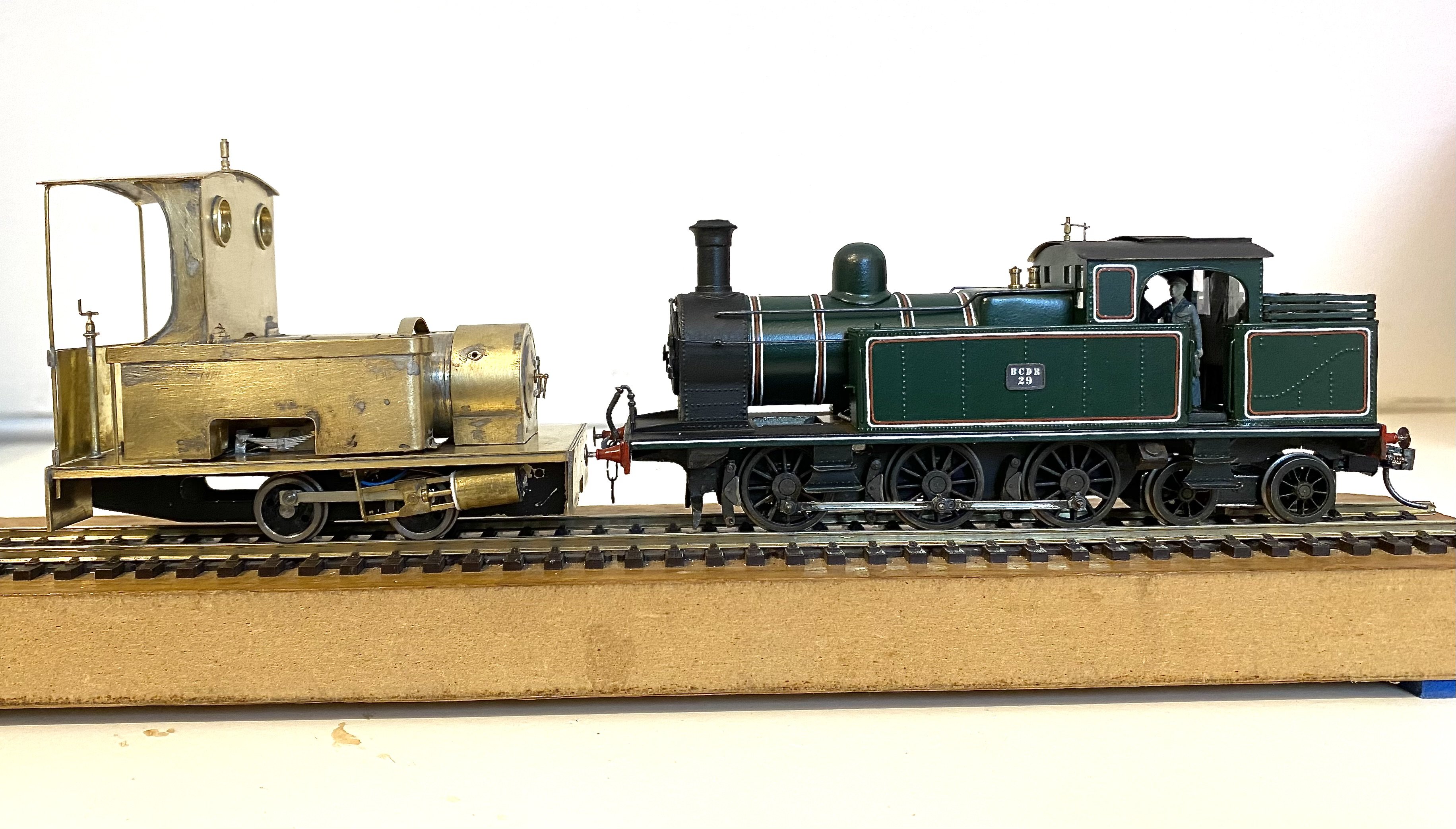
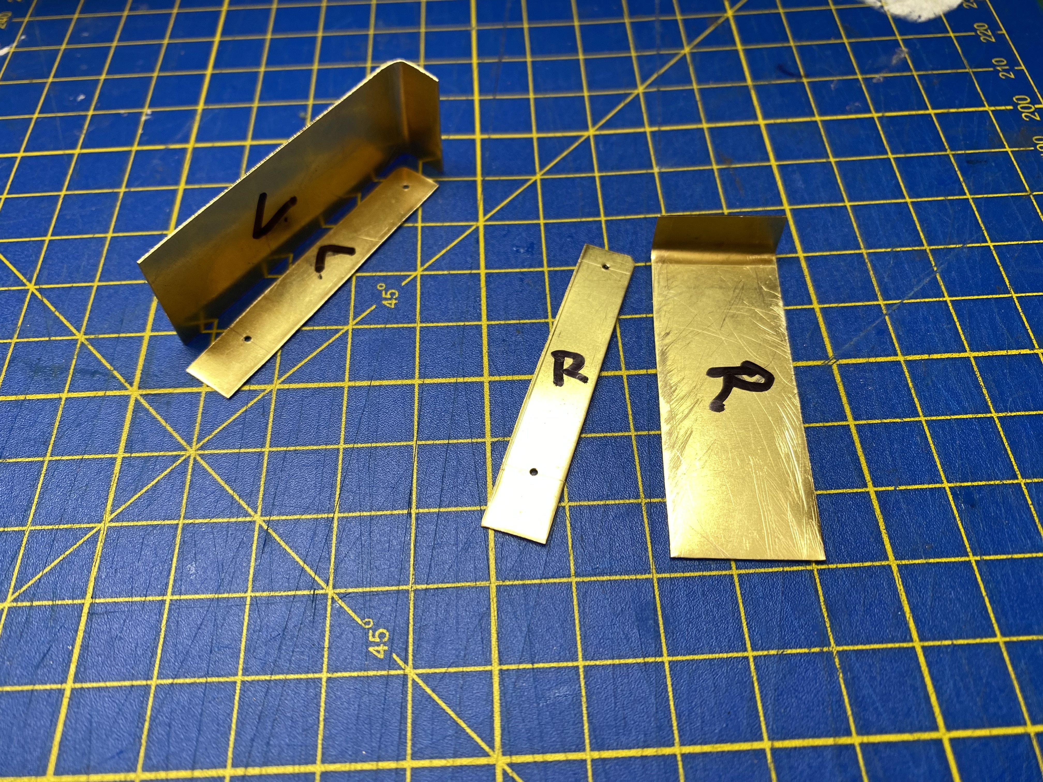
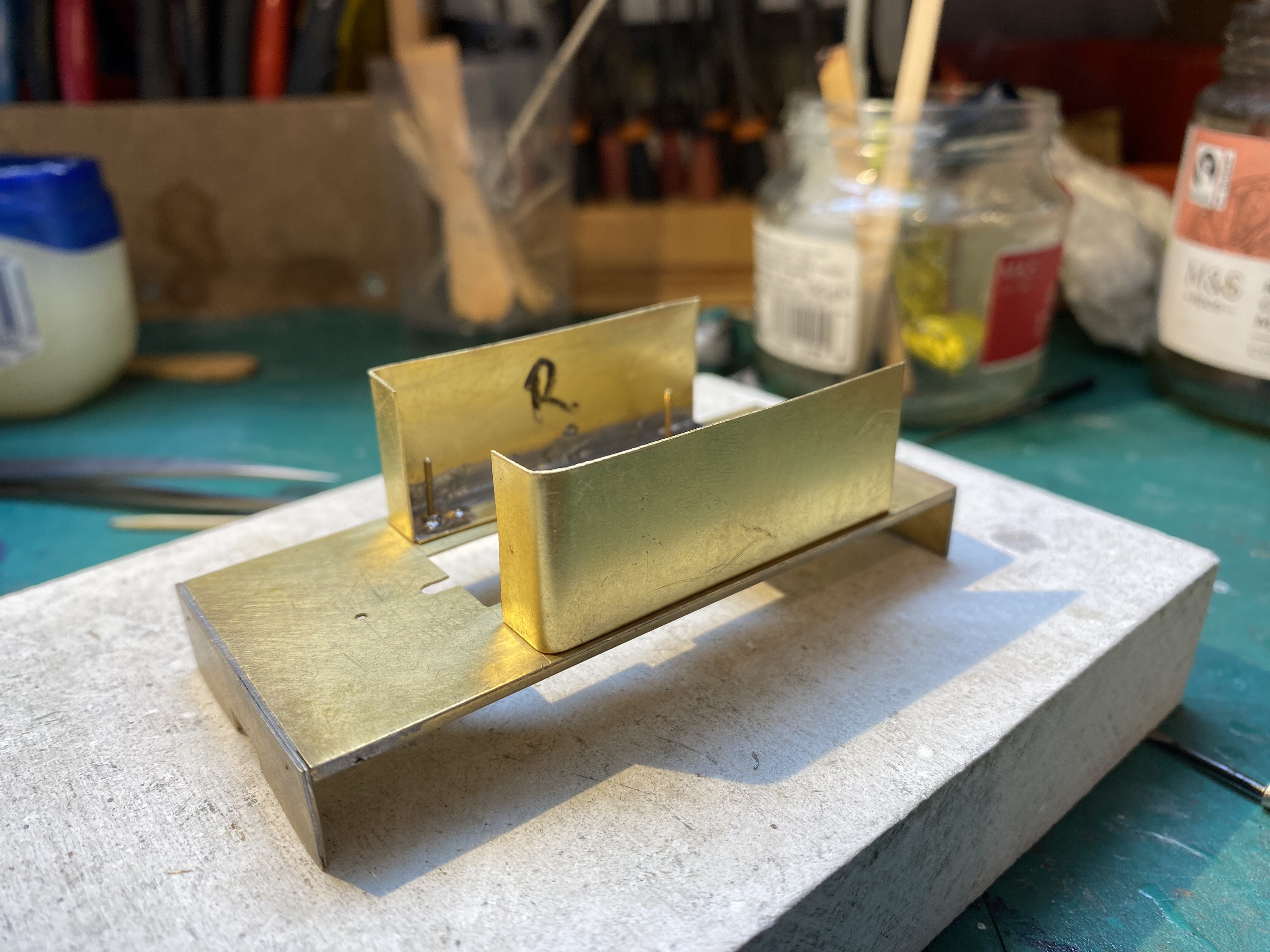
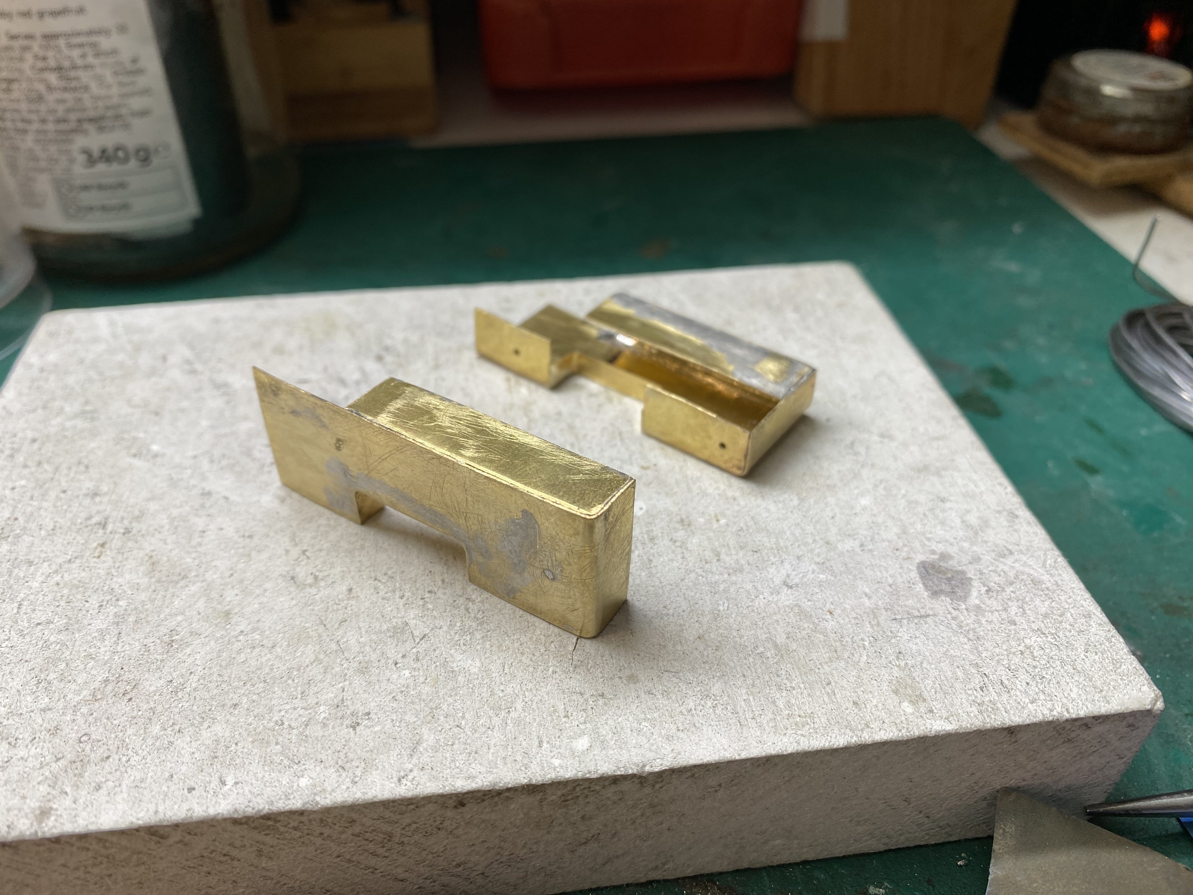
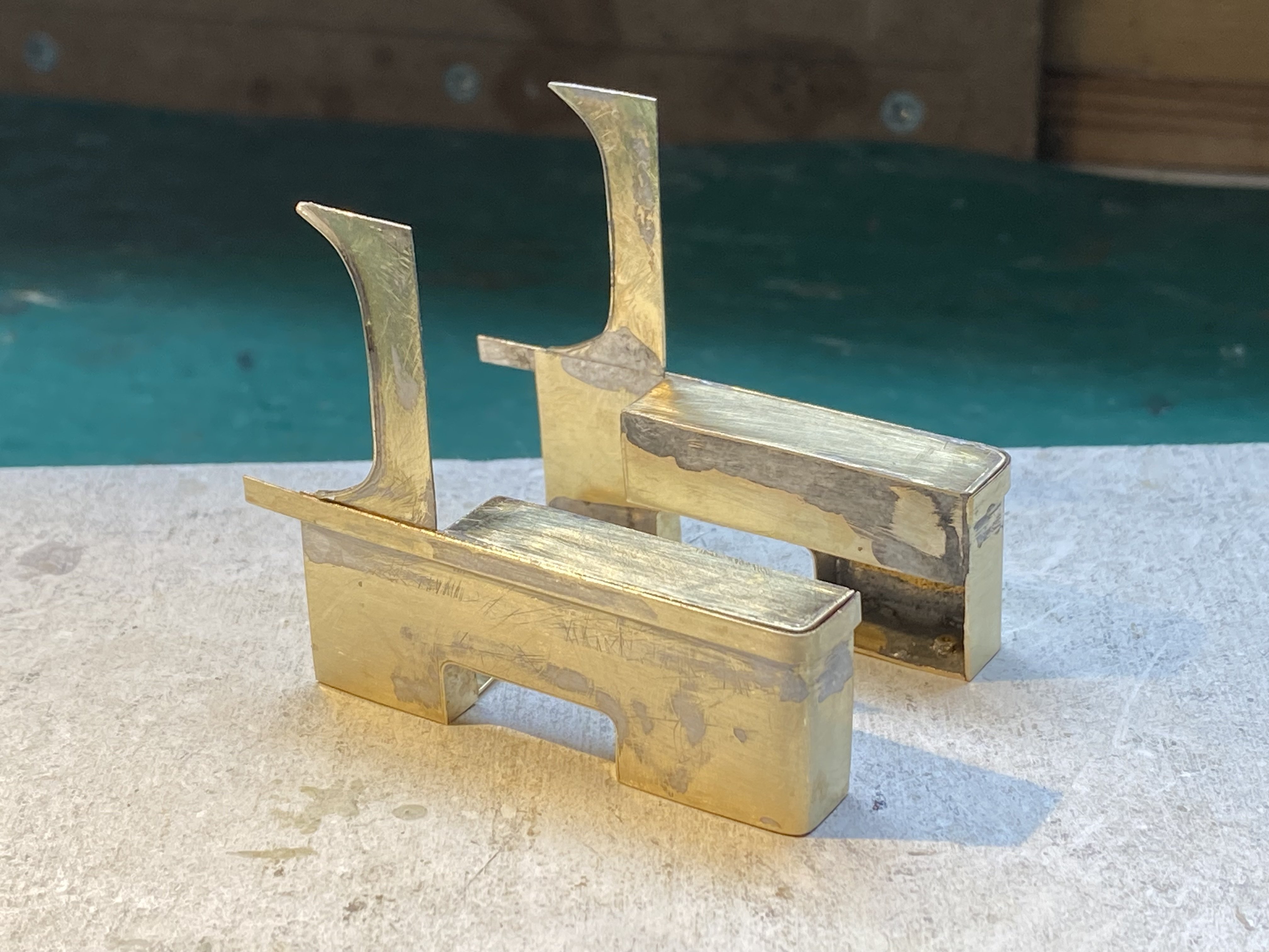
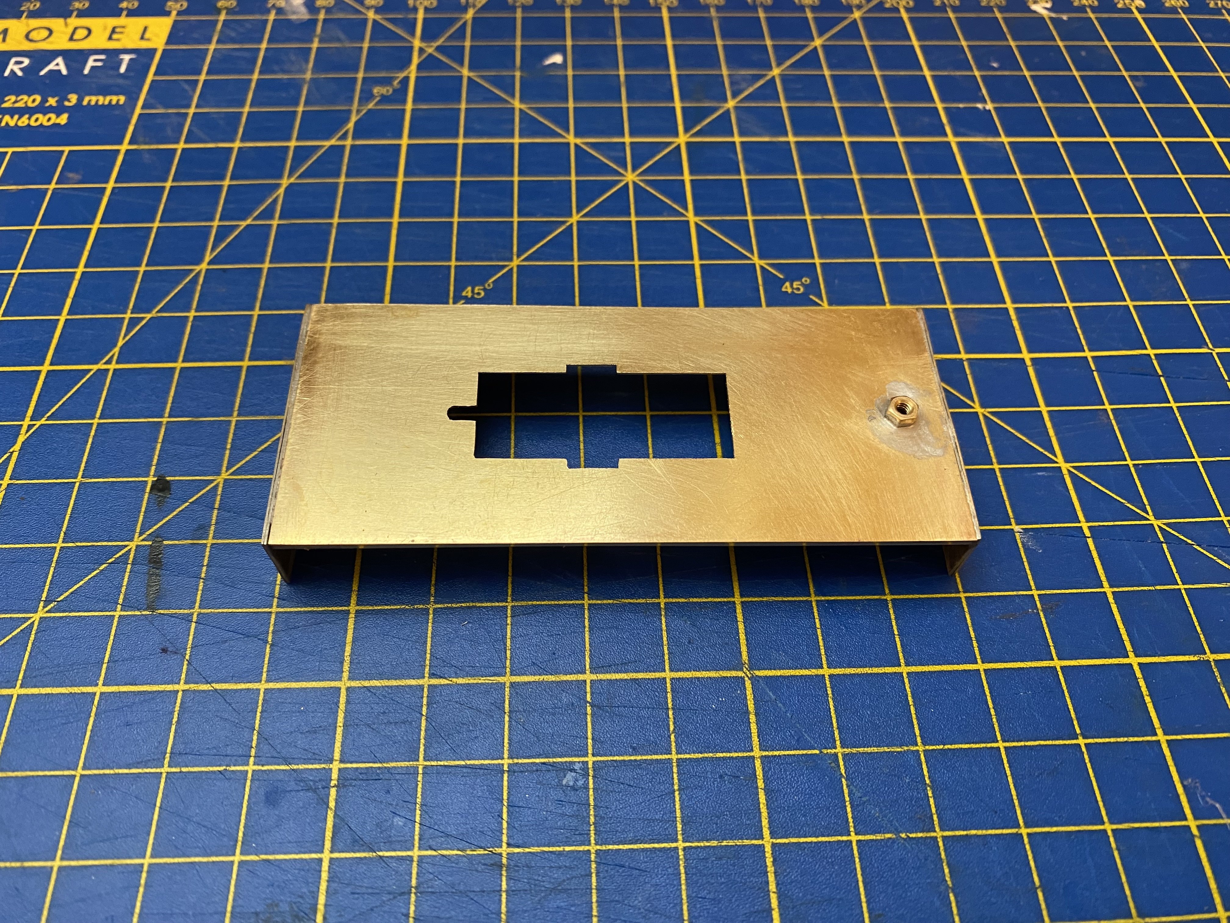
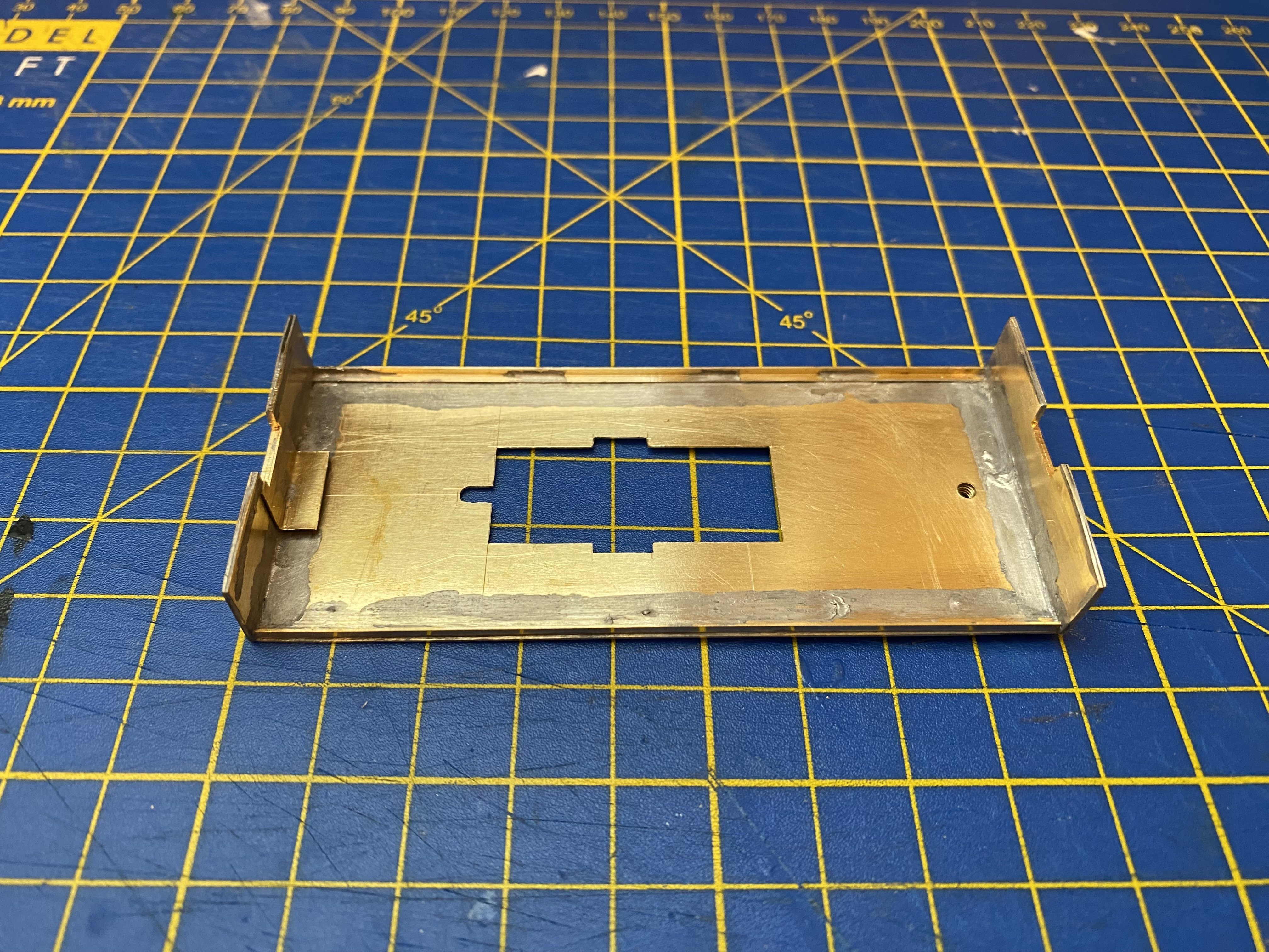
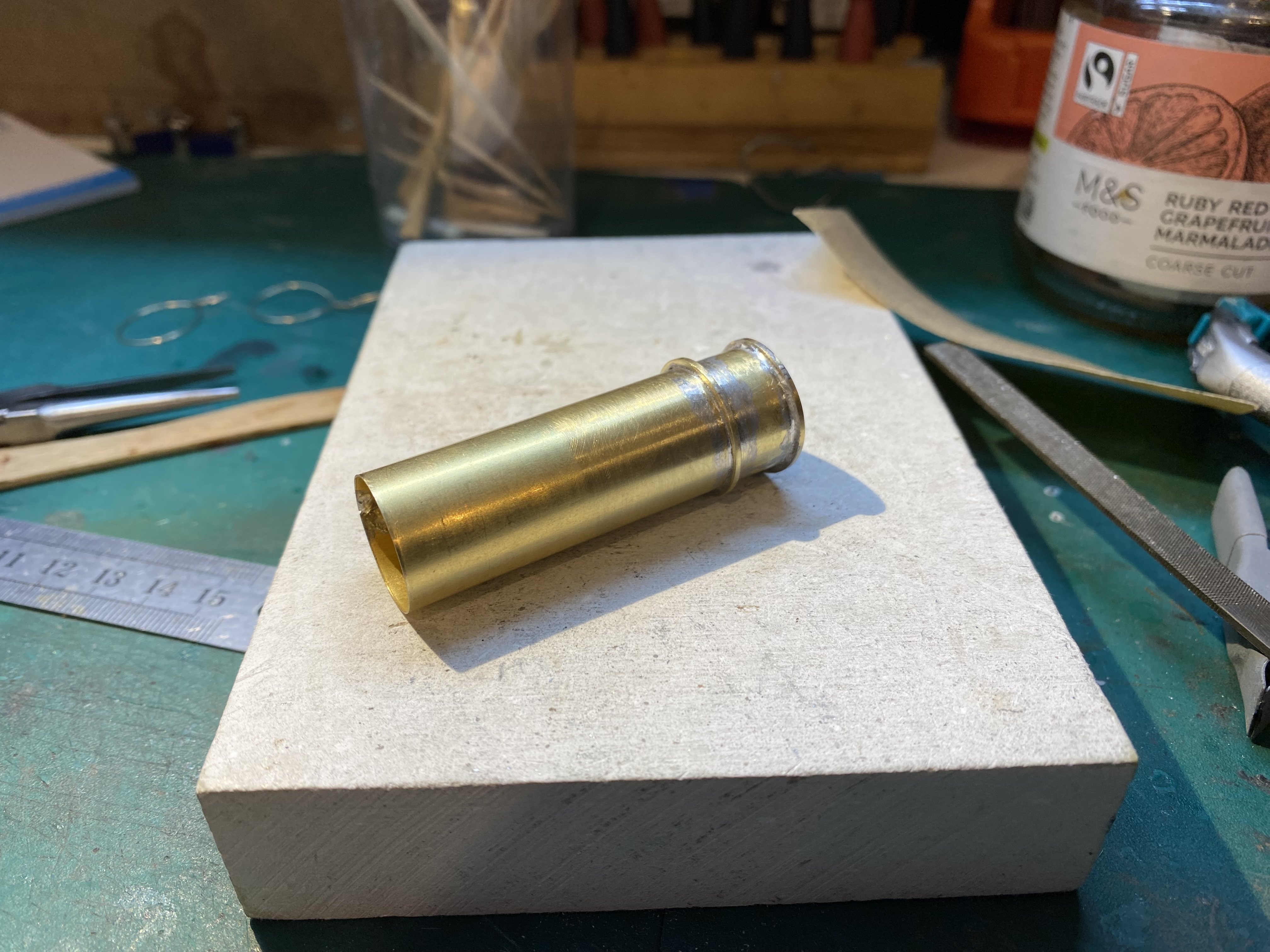
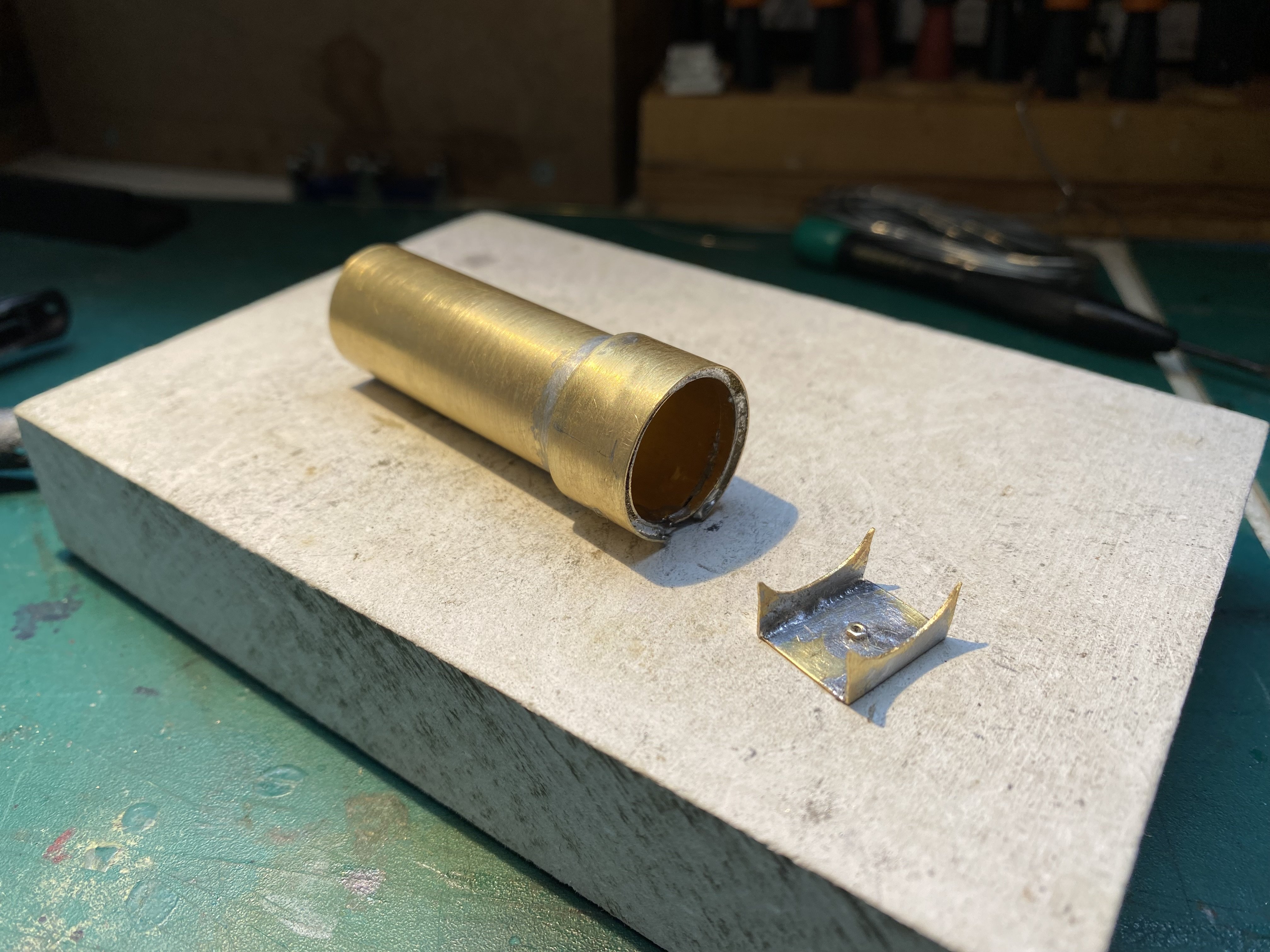
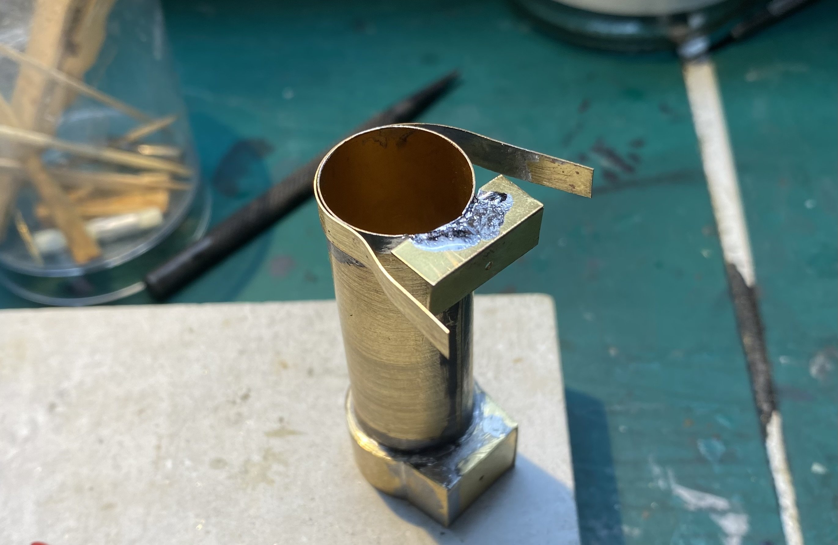
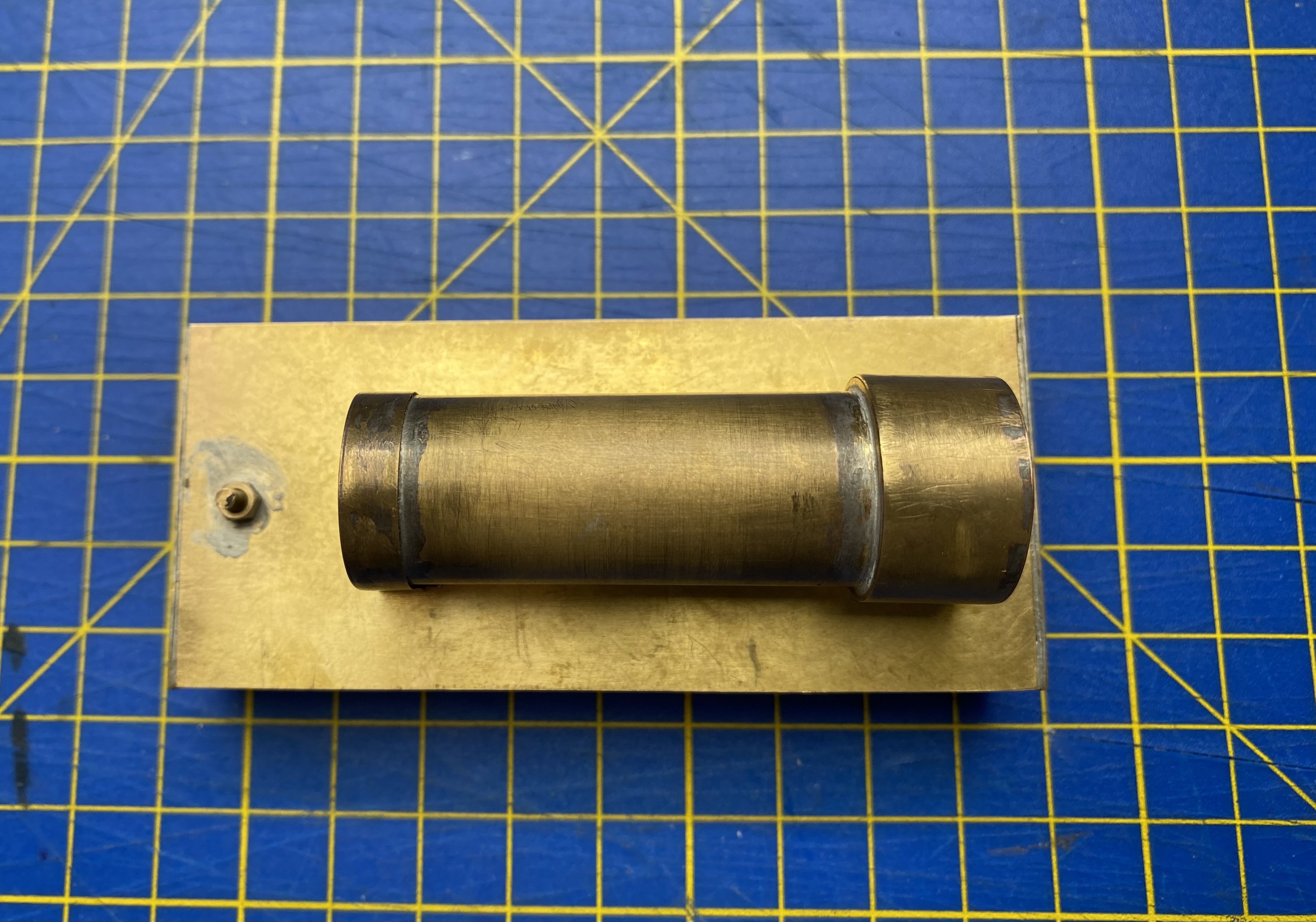
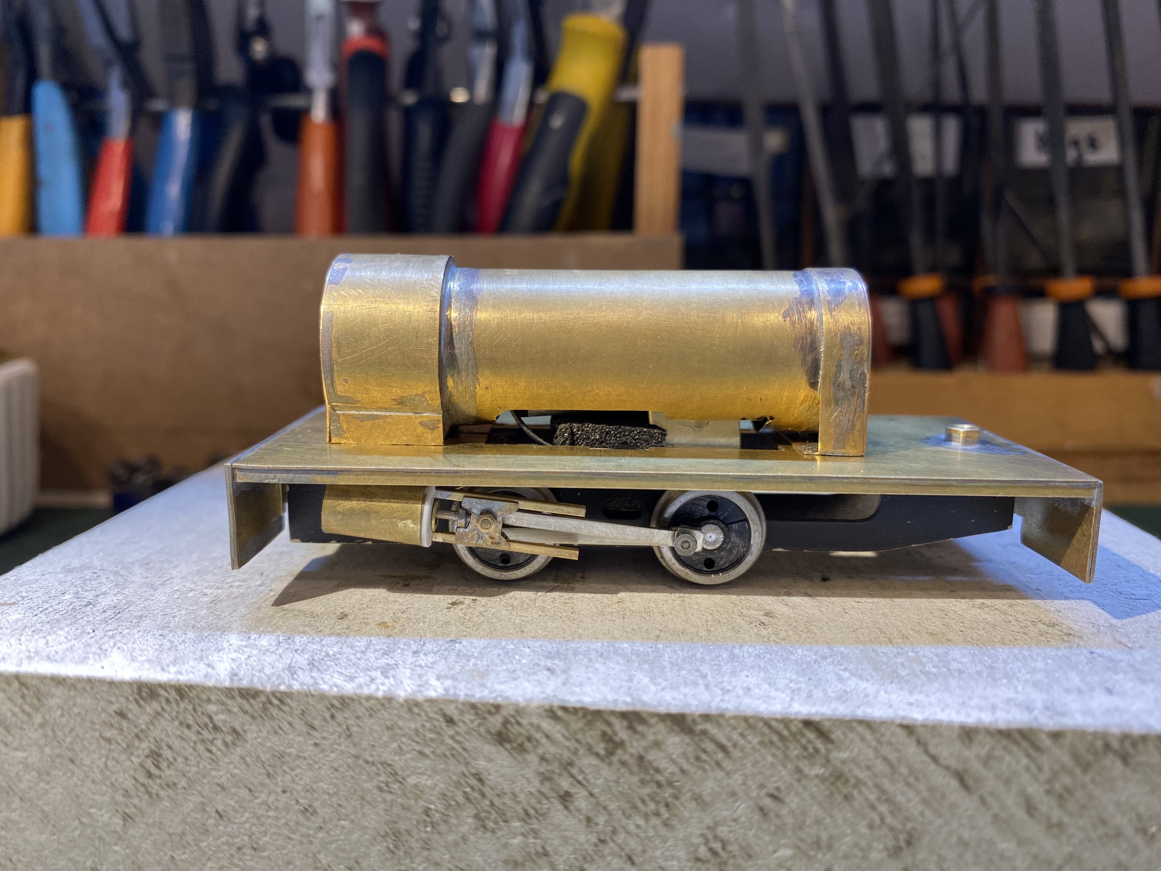
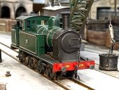
More dodgy weather so more Peckettry. The running plate is made from 0.015" brass with double thicknesses for the buffer beams. The valances are 1.5mm brass angle. A small plate locates the front of the chassis and a 10BA bolt secures it at the back. The boiler is rolled from 0.010" brass with extra layers overlaid at each end for smokebox and firebox. Made the saddles too tall on the first pass, making the boiler sit too high, (where have I heard this story before ) requiring some messy hacking to lower it and get the captive nuts back into their allotted places. All a bit of a fudge but it came out ok in the end. Boiler bottom cut away to clear the motor and gearbox. Now, rain or no rain, there's an overgrown lawn needing my attention. Temporarily exchanging soldering iron for scythe, Alan
- 641 replies
-
- 12
-
-
-
Yes, took me a while to suss that. Slow learner Thanks again. I think we've now got most of the dead chinchillas out of Patrick's pride and joy. At least the crunching noises have disappeared. And none of the little critters got as far as the drive train so big relief all round.
-
Thanks Ken. I like the sound of your Peckett. Have you posted anything on it? Regarding the wheels, I'm assuming the Gibson crankpin bushes don't have a large enough outside diameter to fill the holes in the rods? Alan PS Found your Peckett. Lovely, lovely stuff!
-
Many thanks for this. Found the 4 clips but there seems to be a clip at each end of the baseplate as well. and I can’t for the life of me see how they unclip. Fearful of doing damage here postscript: Ah, got it! Perseverance and verbal blandishments in equal measure
-
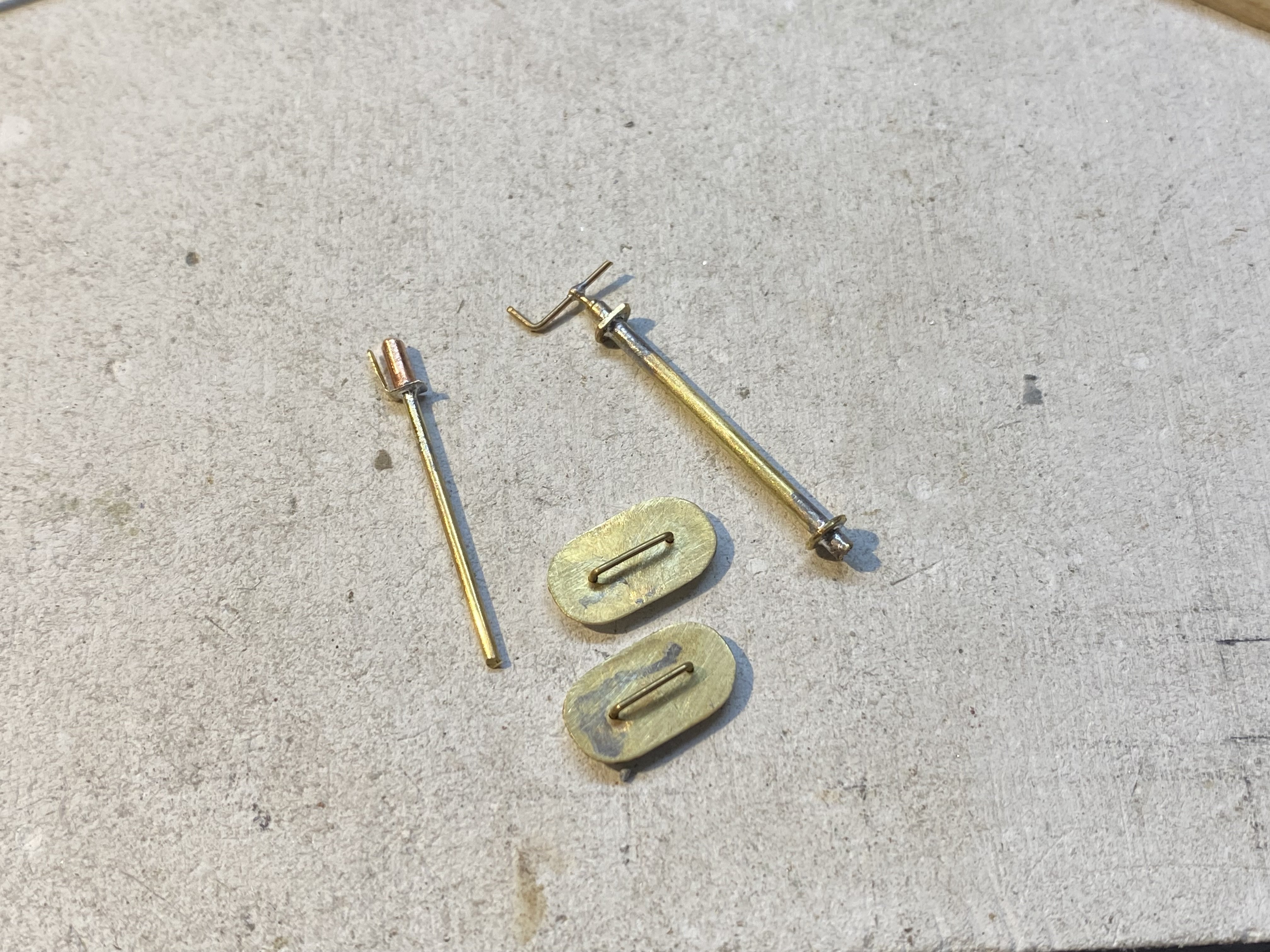
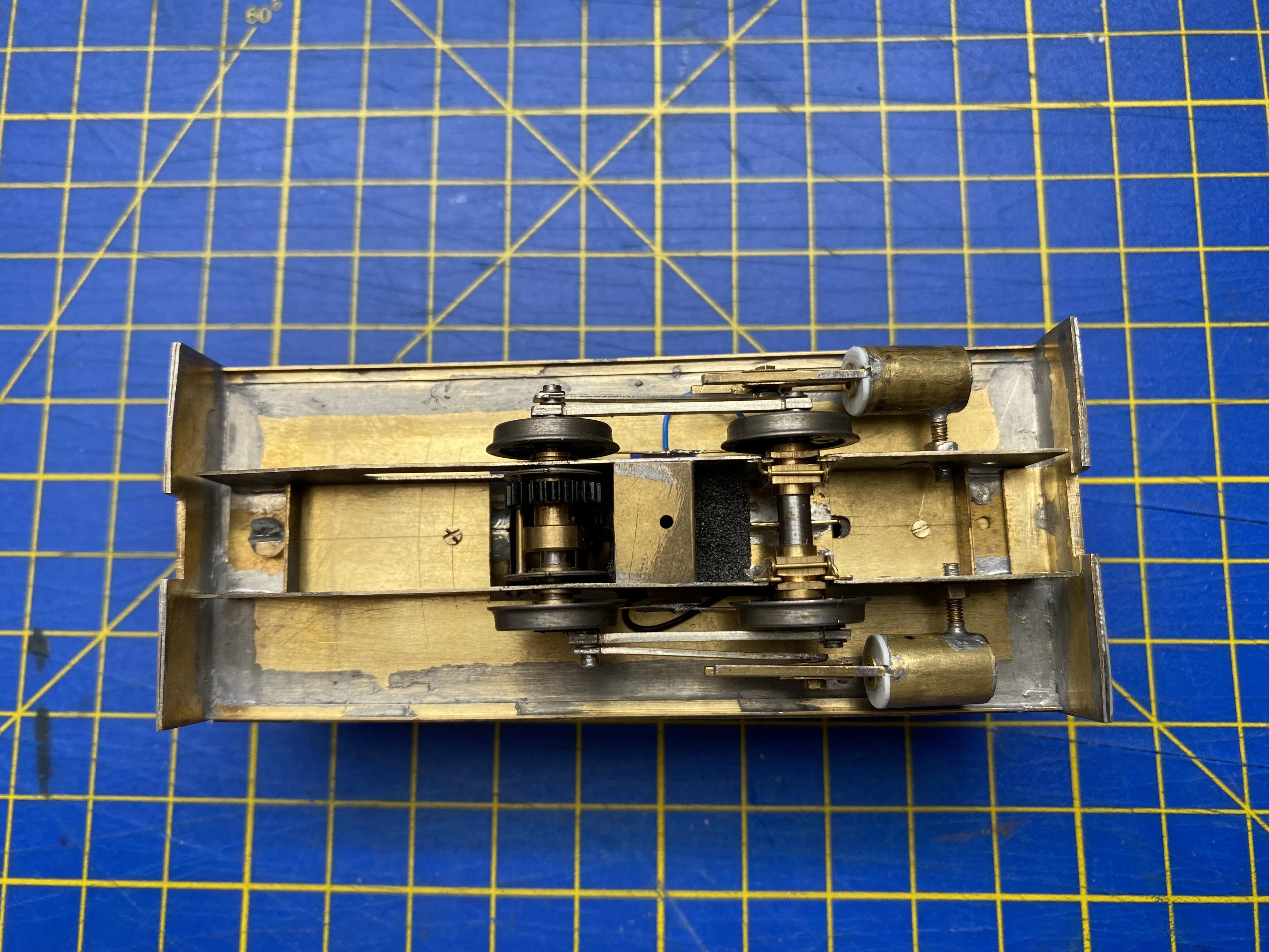
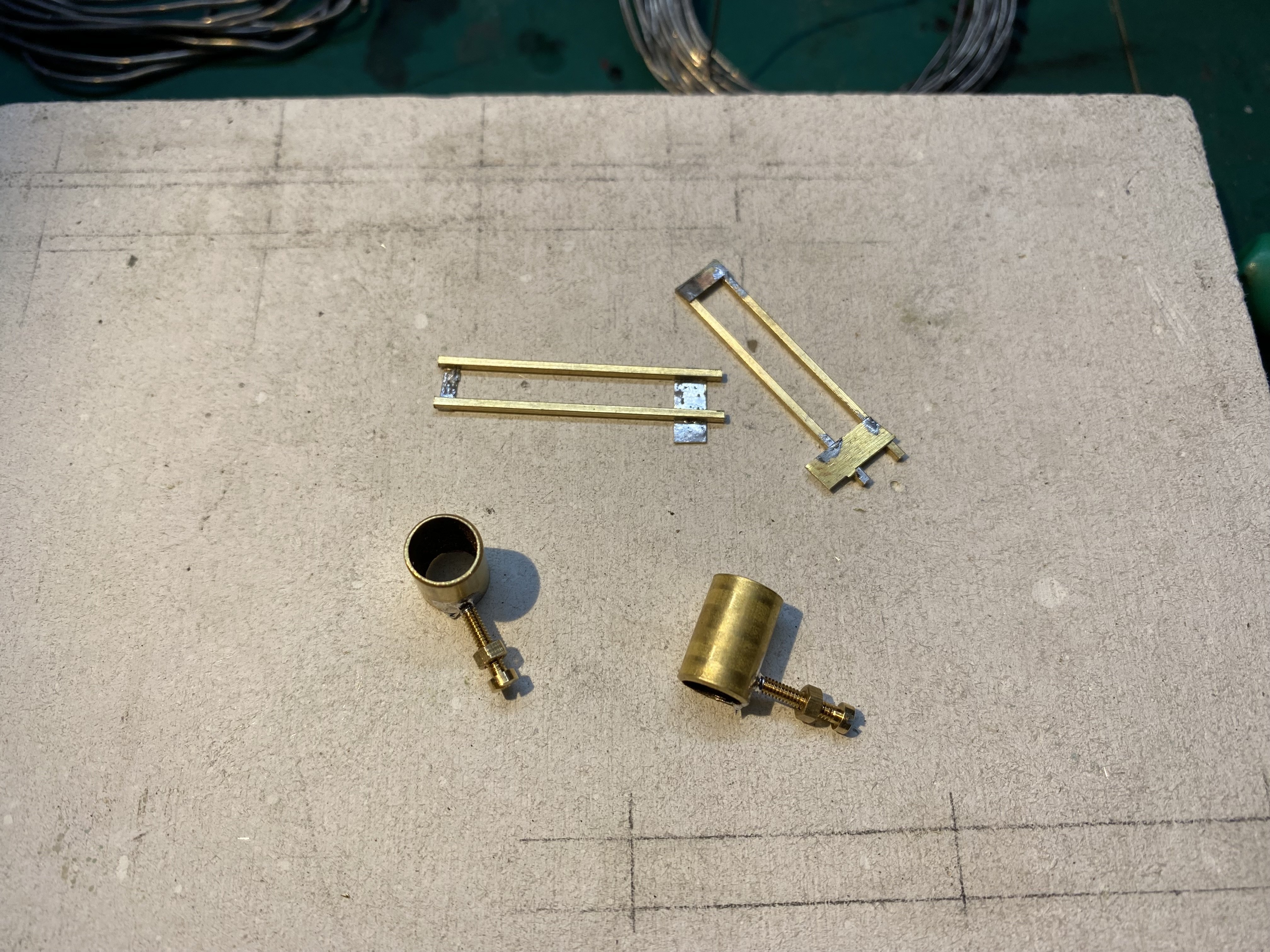
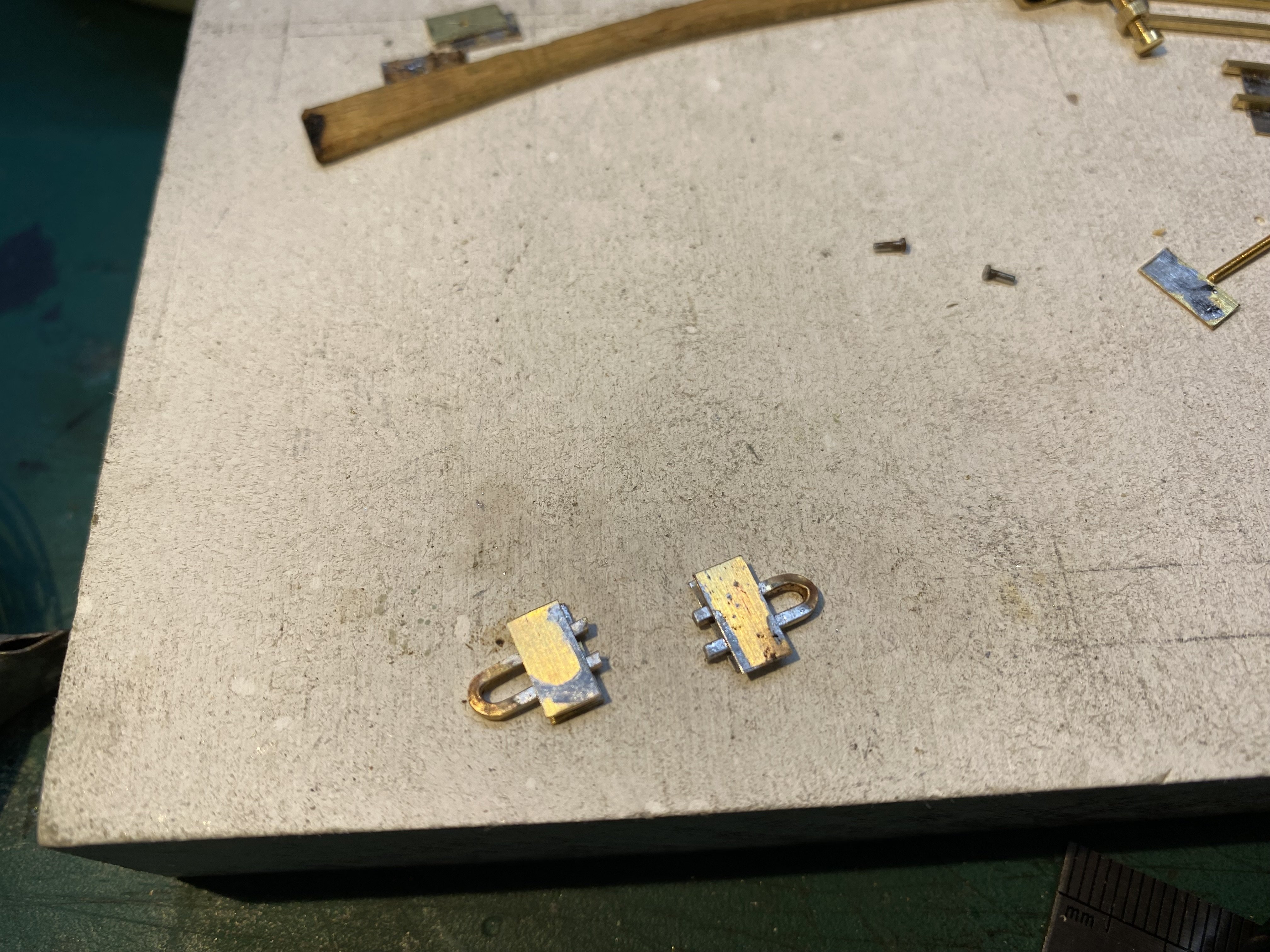
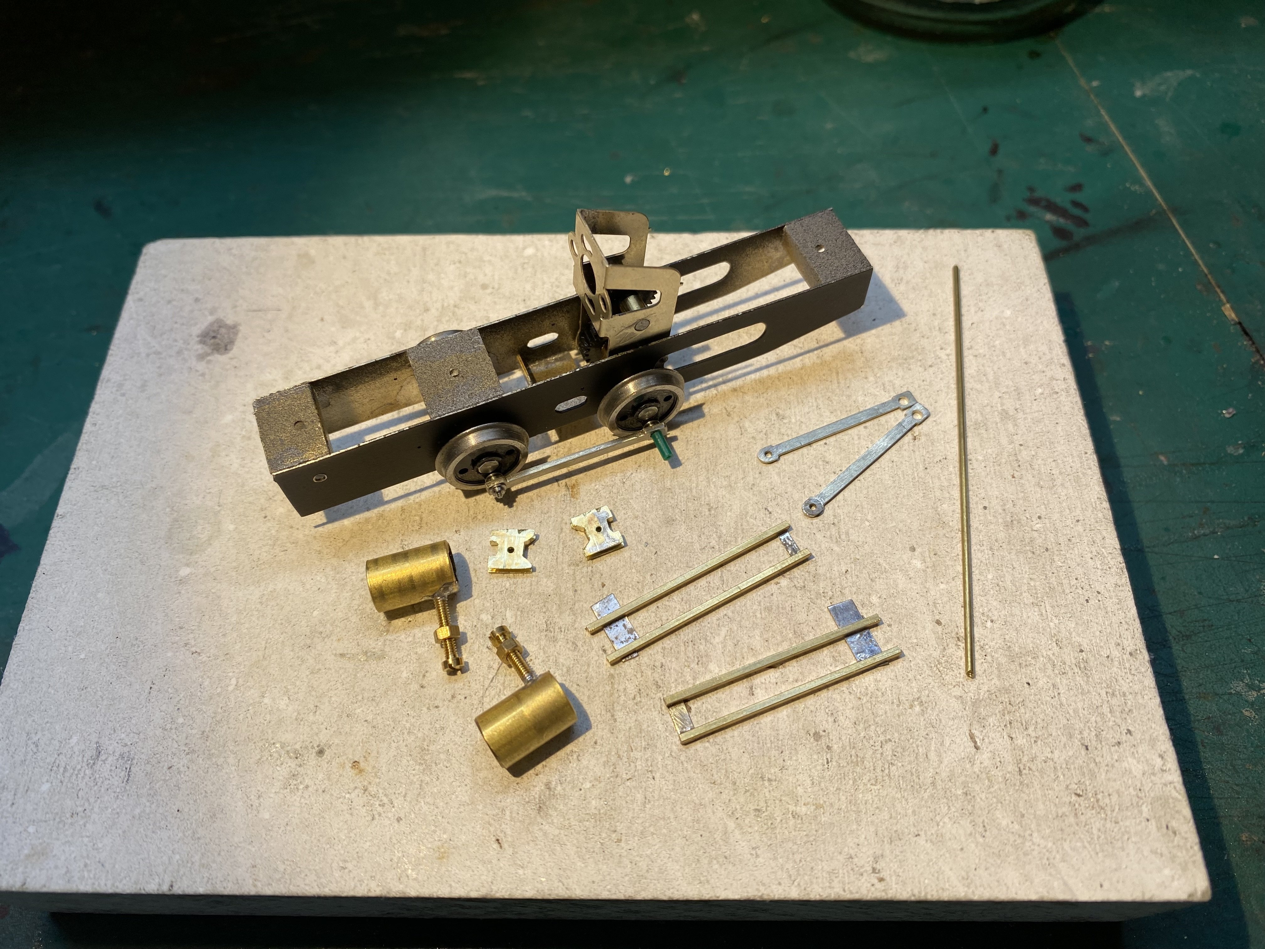
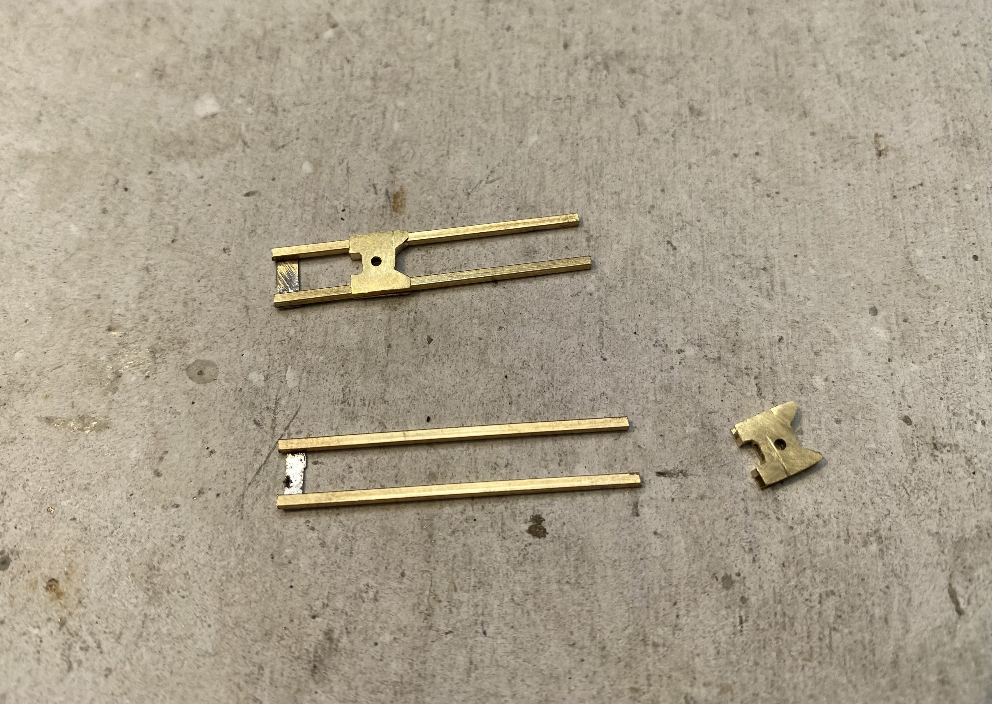
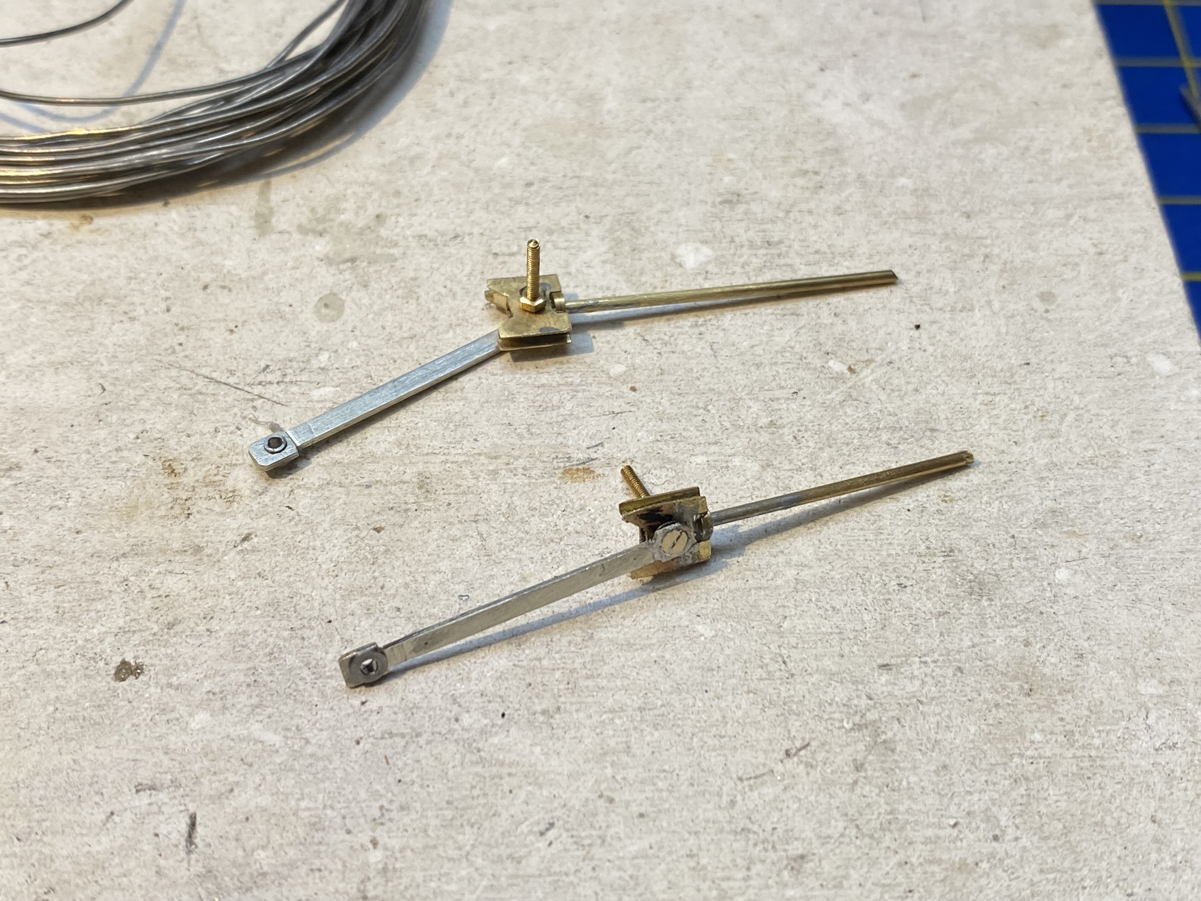
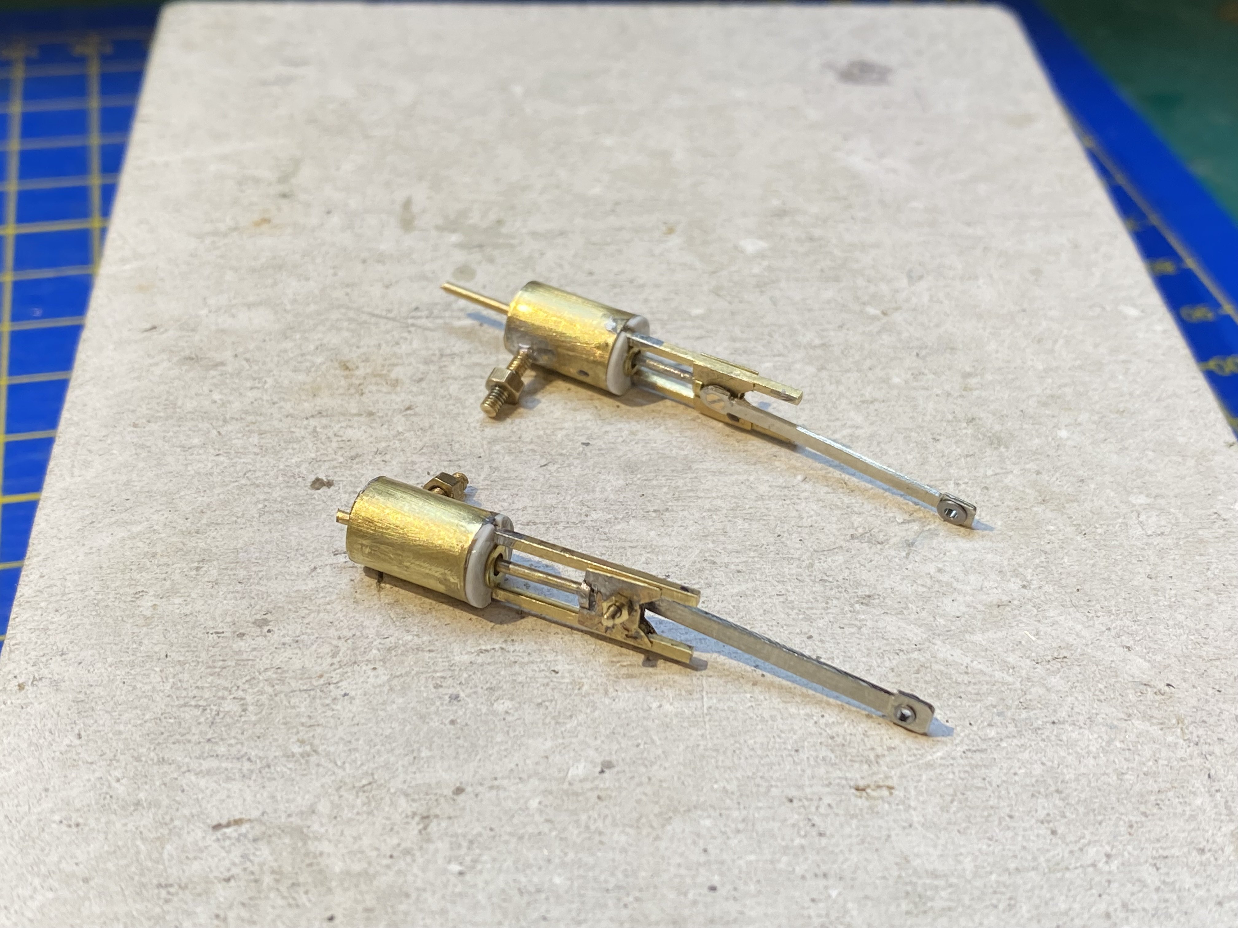
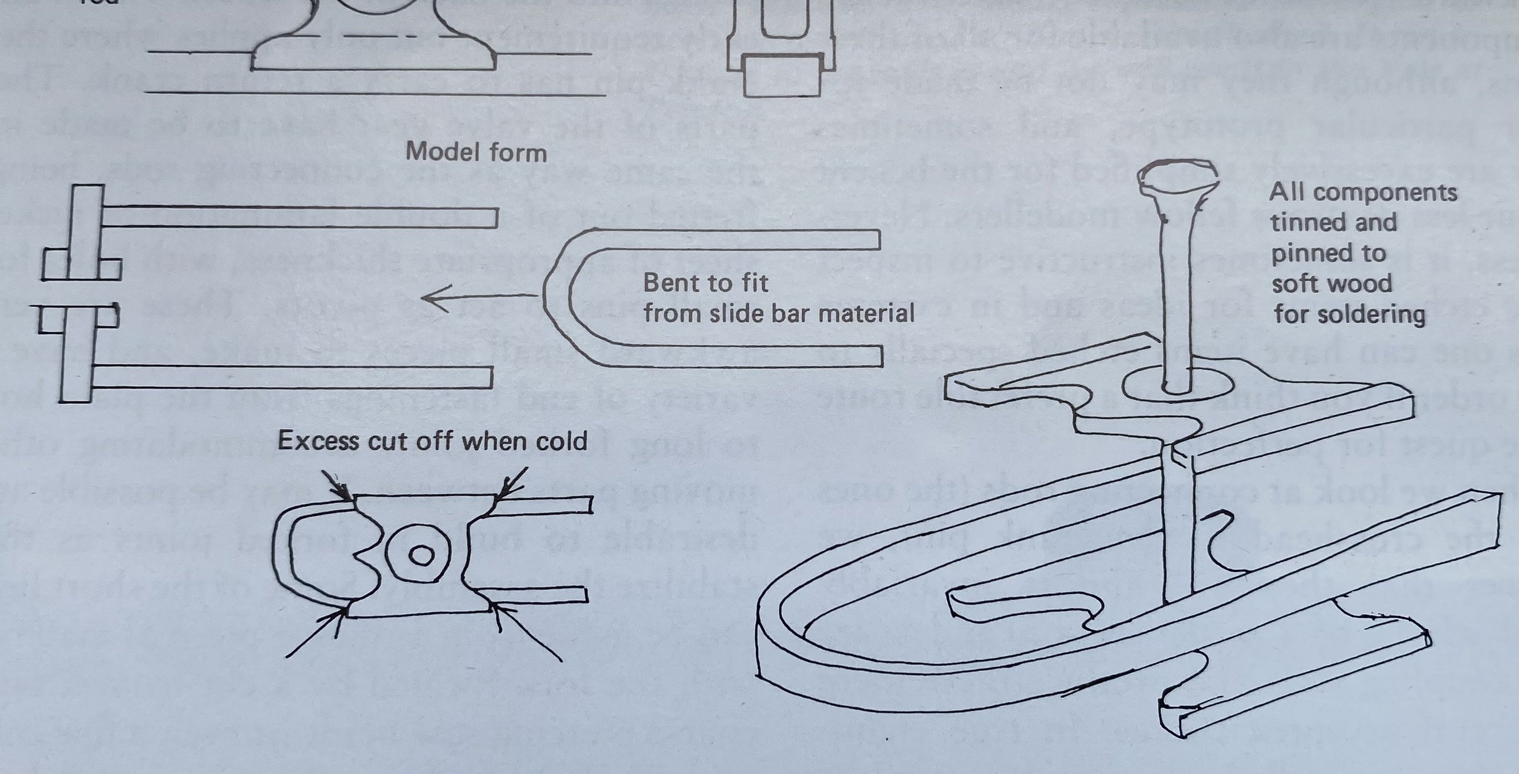
Weather has been exceedingly wet all week so some progress on the narrow gauge Peckett chassis with a few fiddly bits made after a struggle or two. Cylinders cut from 12mm o.d. brass tube and slide bars from 1x1mm square brass bar. The 10BA bolts are for attaching the cylinders to the chassis frames. Usual practice would be to mount the cylinders on a saddle that straddles the chassis. I wasn't confident I could calculate how far apart the cylinders would need to be to get clearance behind the crossheads so I did it this way to allow me to adjust each one individually. Bit of a fiddle. I made crossheads following a method described by Guy Williams ("The 4mm Engine, A Scratchbuilder's Guide", Wild Swan, 1988). He made it sound easy. Ha! (Image courtesy Wild Swan Publications Ltd) It took me two+ attempts and a number of disasters to get something that worked... .. but eventually there emerged a kit of parts... ... and the bones of a working chassis. The rubber band is by way of a temporary restraining order on the motor. IMG_8041.MOV Well, that was more fun than gardening in the rain Alan
- 641 replies
-
- 12
-
-