Tullygrainey
-
Posts
934 -
Joined
-
Last visited
-
Days Won
55
Content Type
Profiles
Forums
Events
Gallery
Blogs
Store
Community Map
Everything posted by Tullygrainey
-
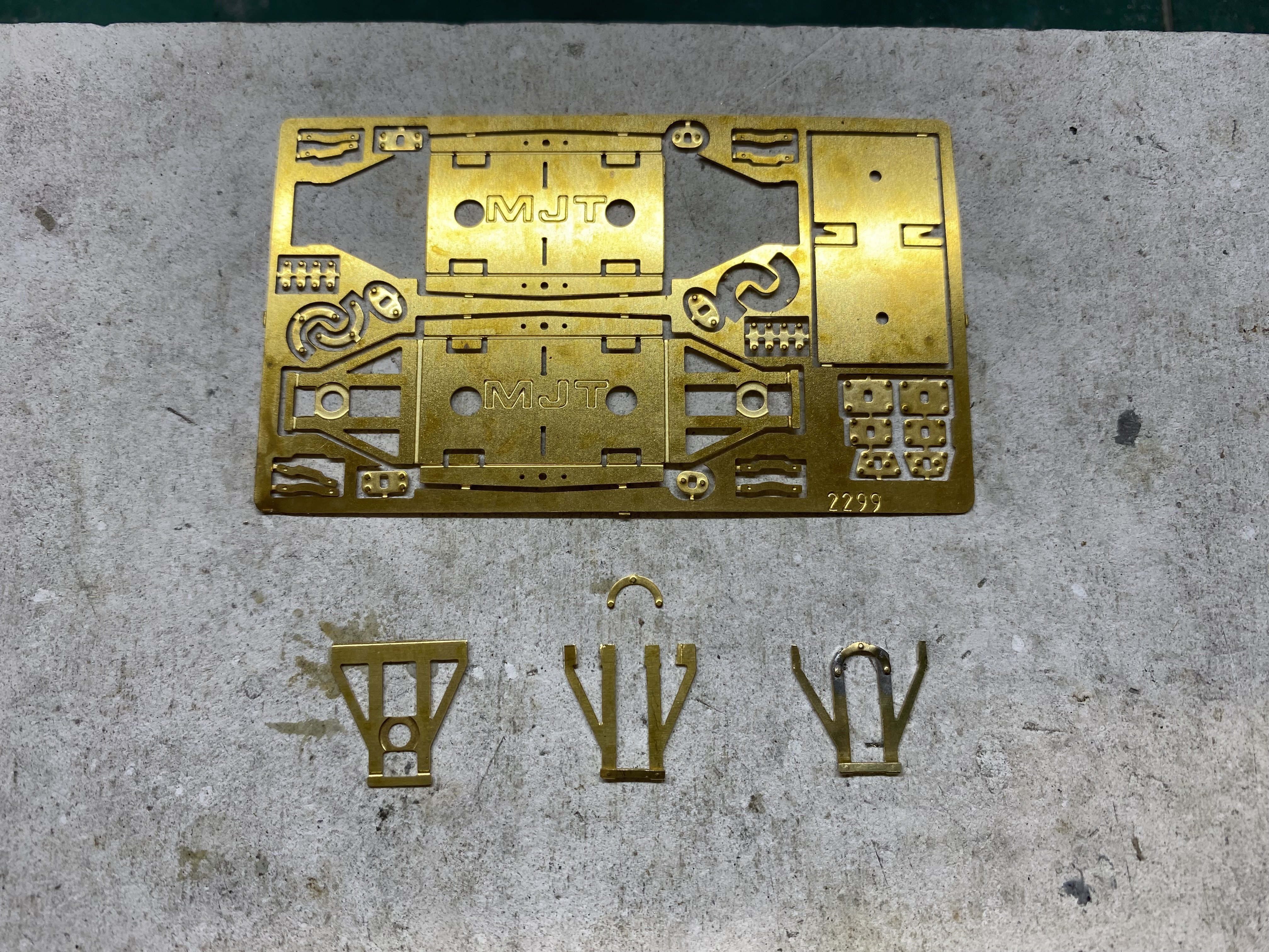
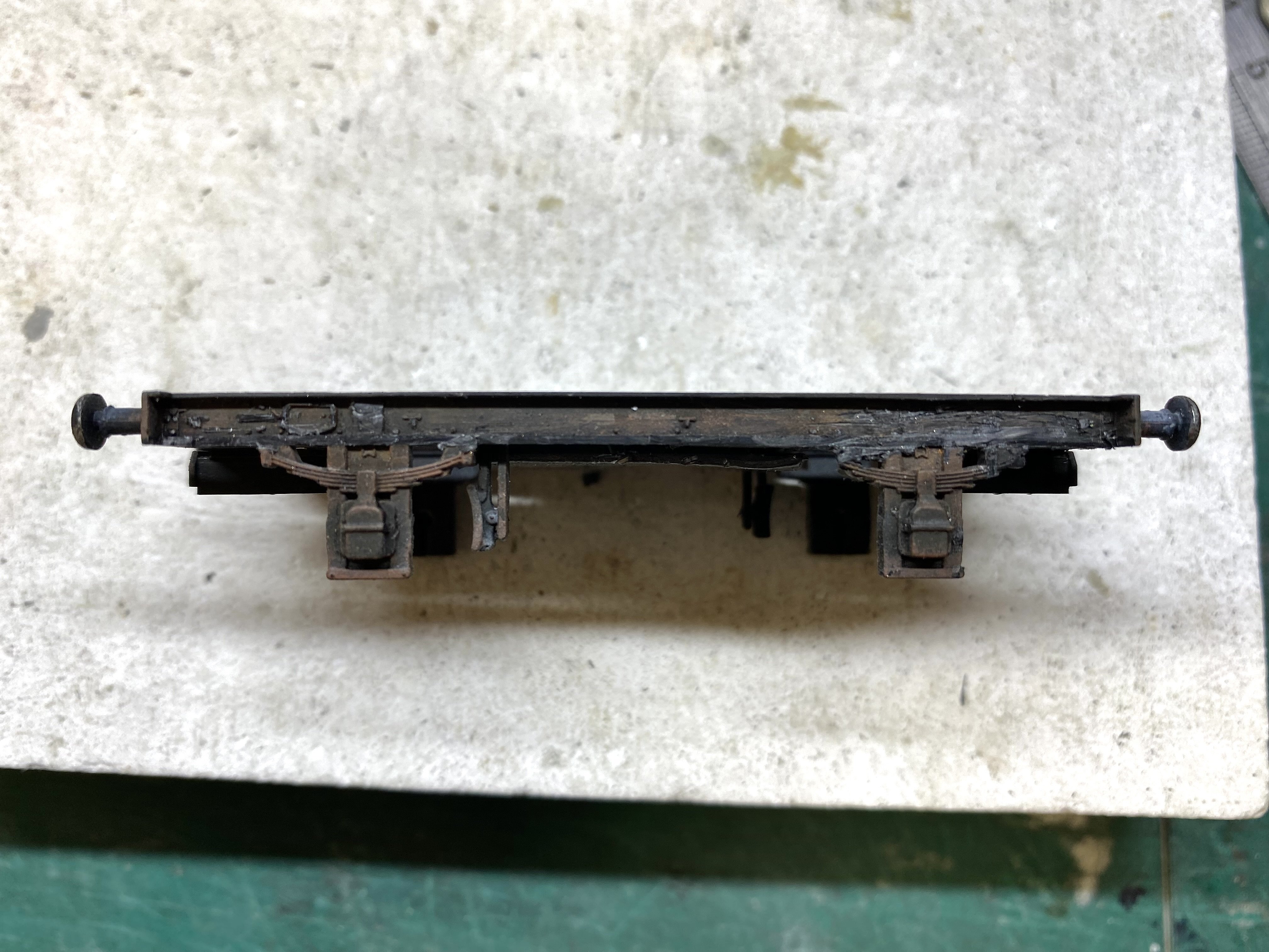
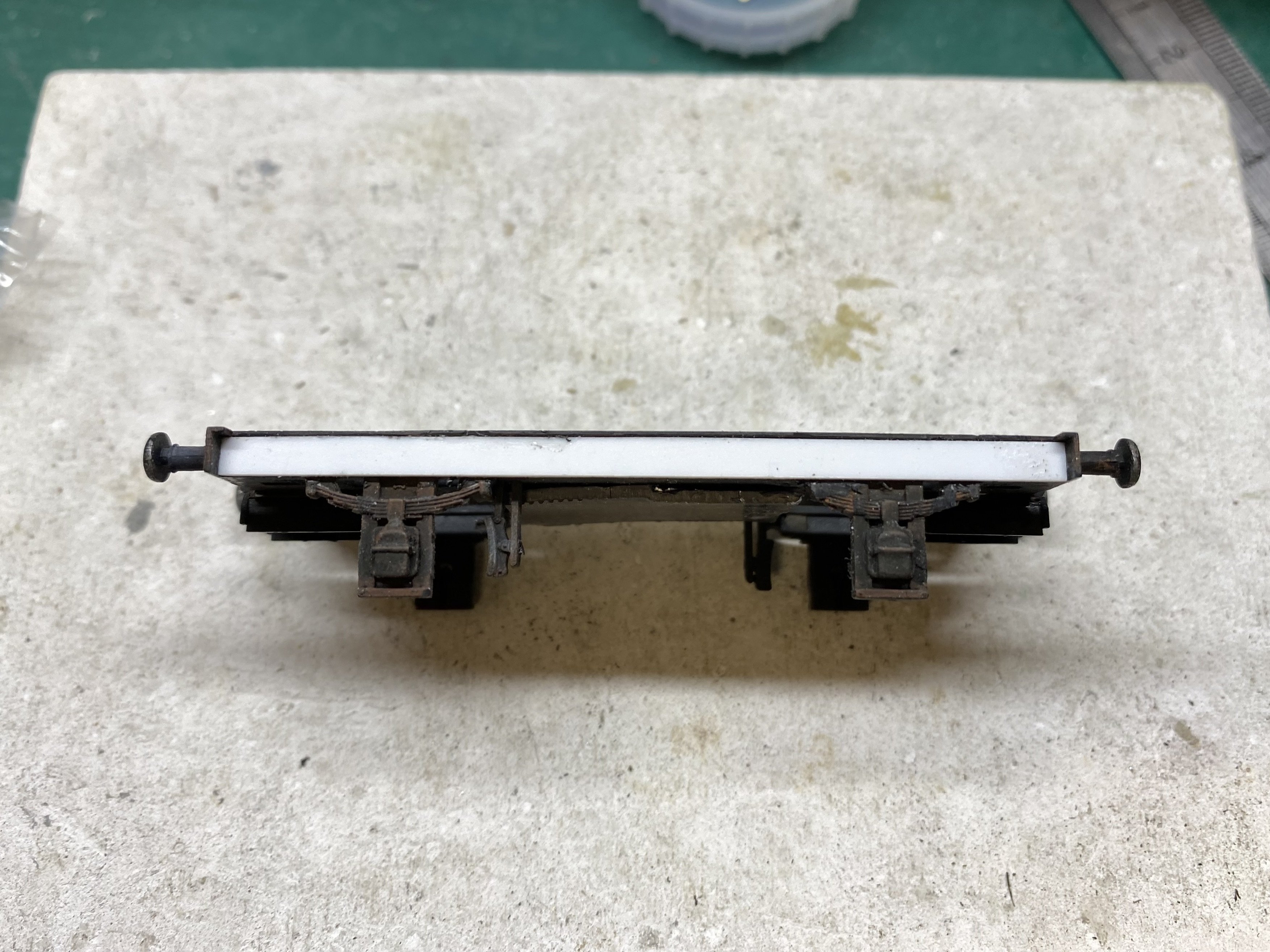
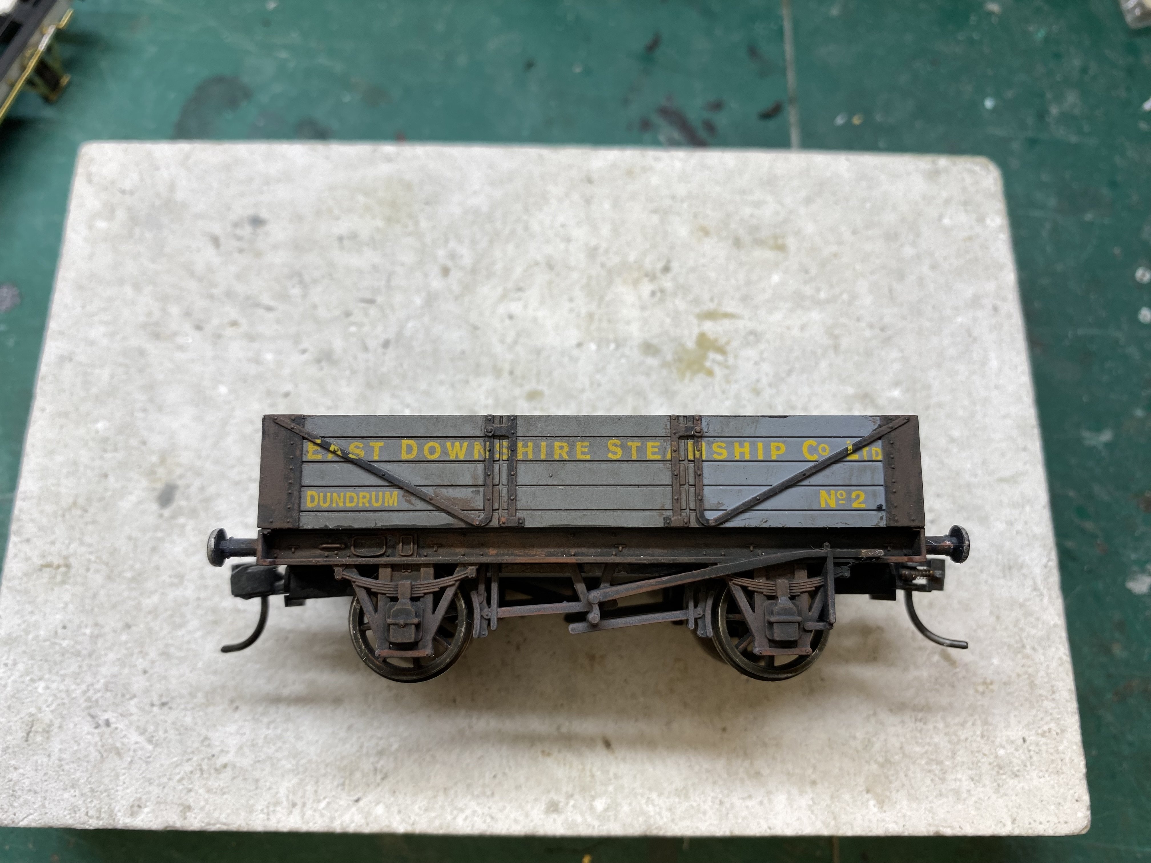
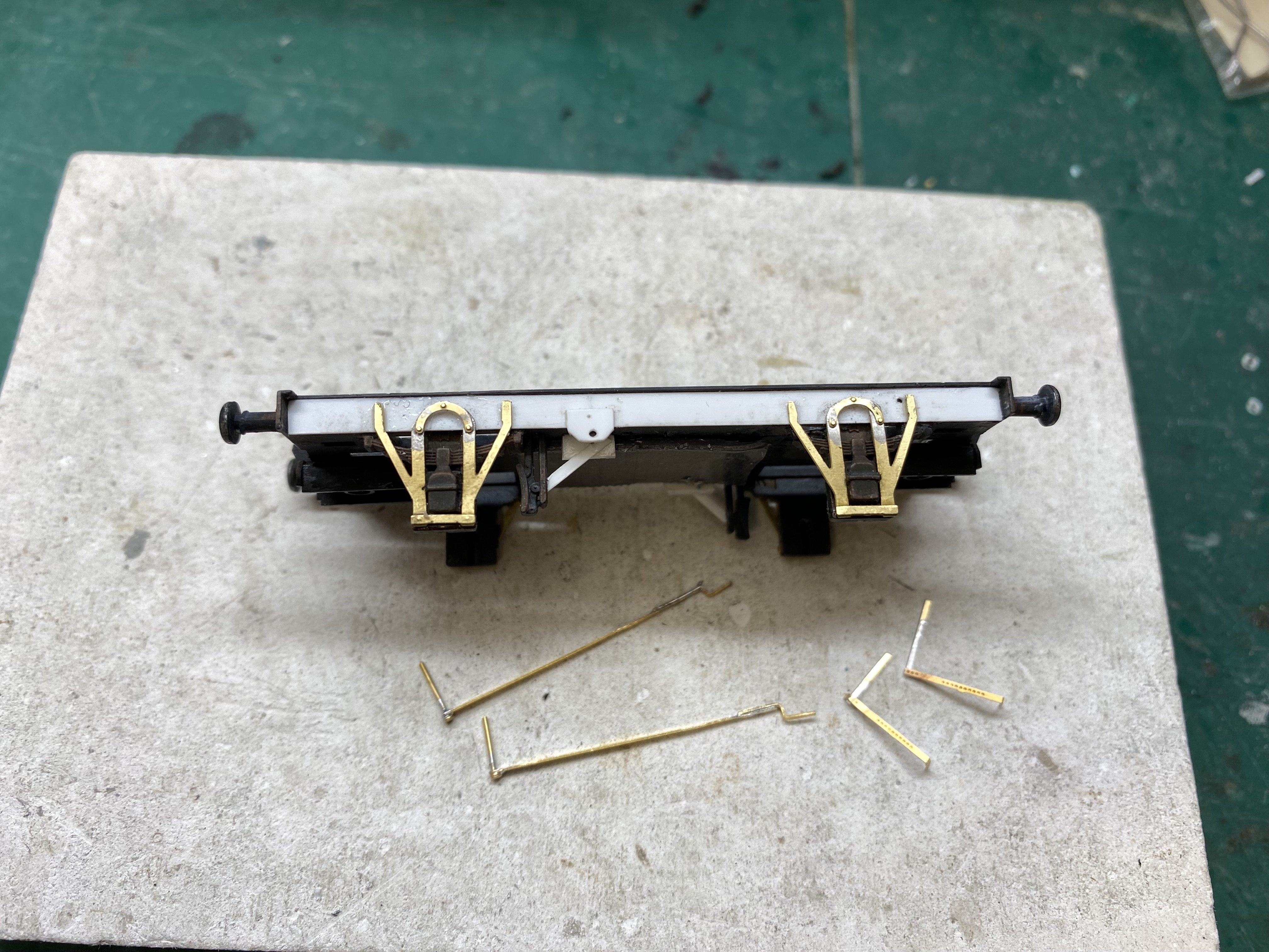
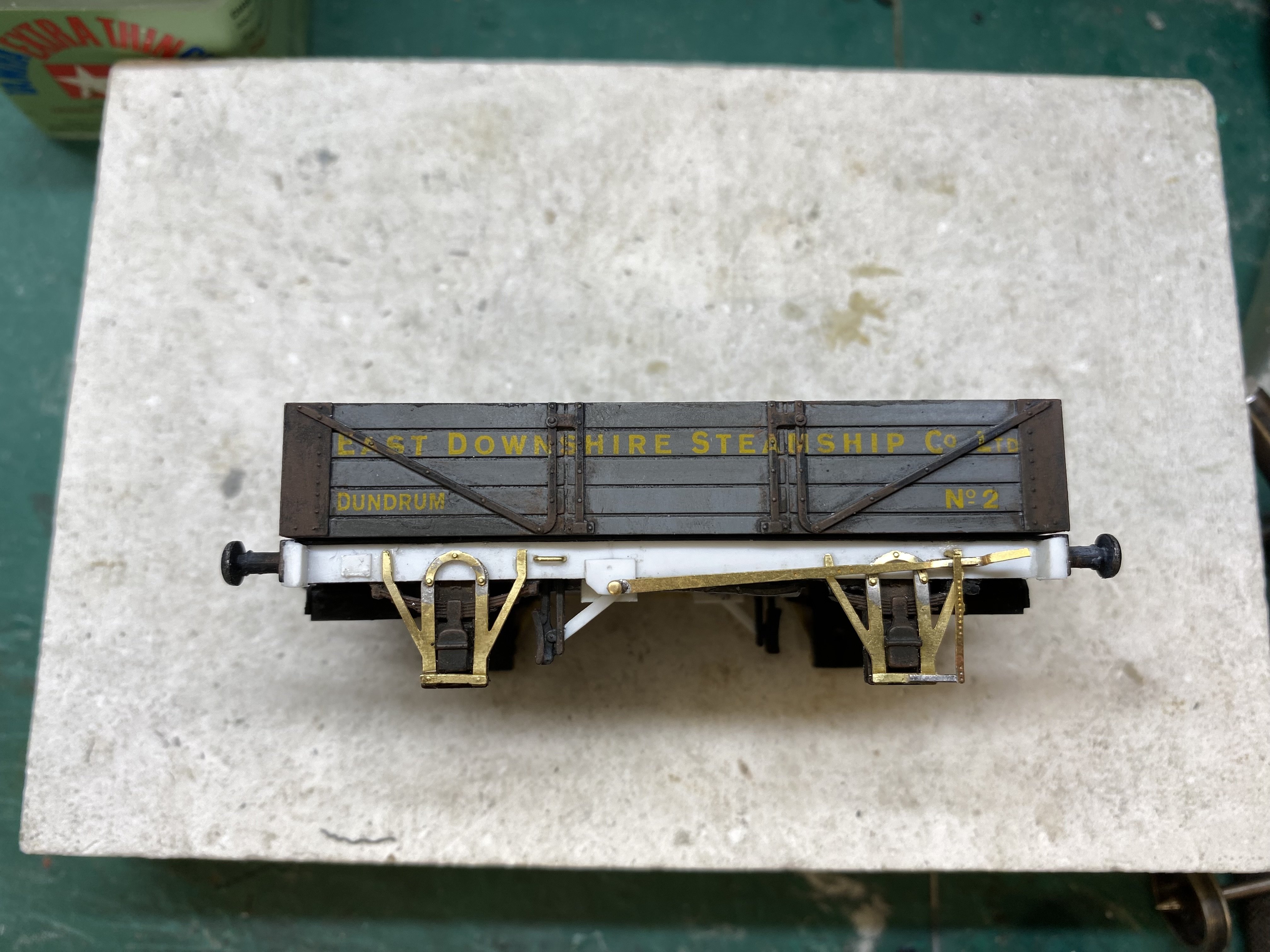
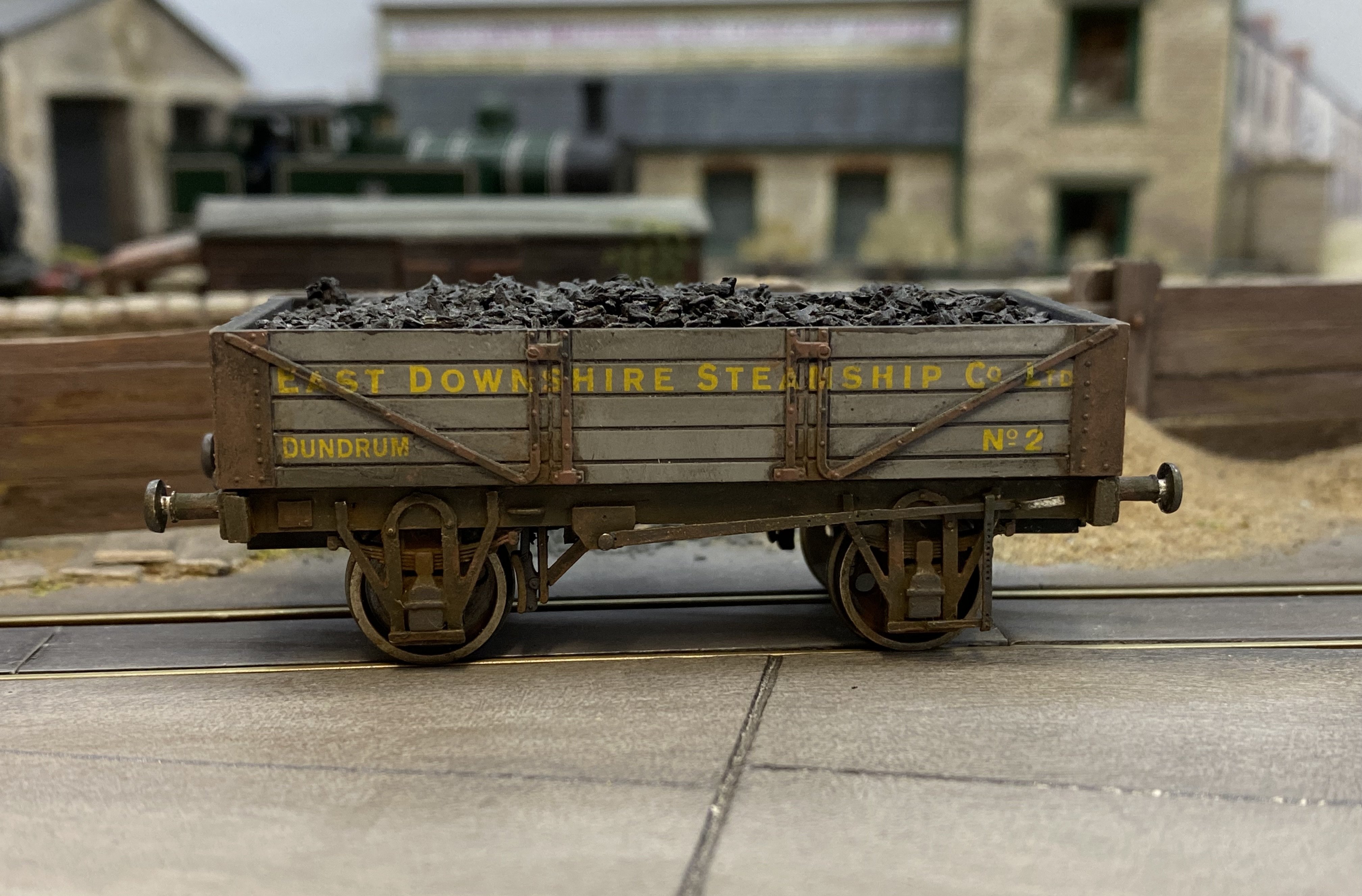
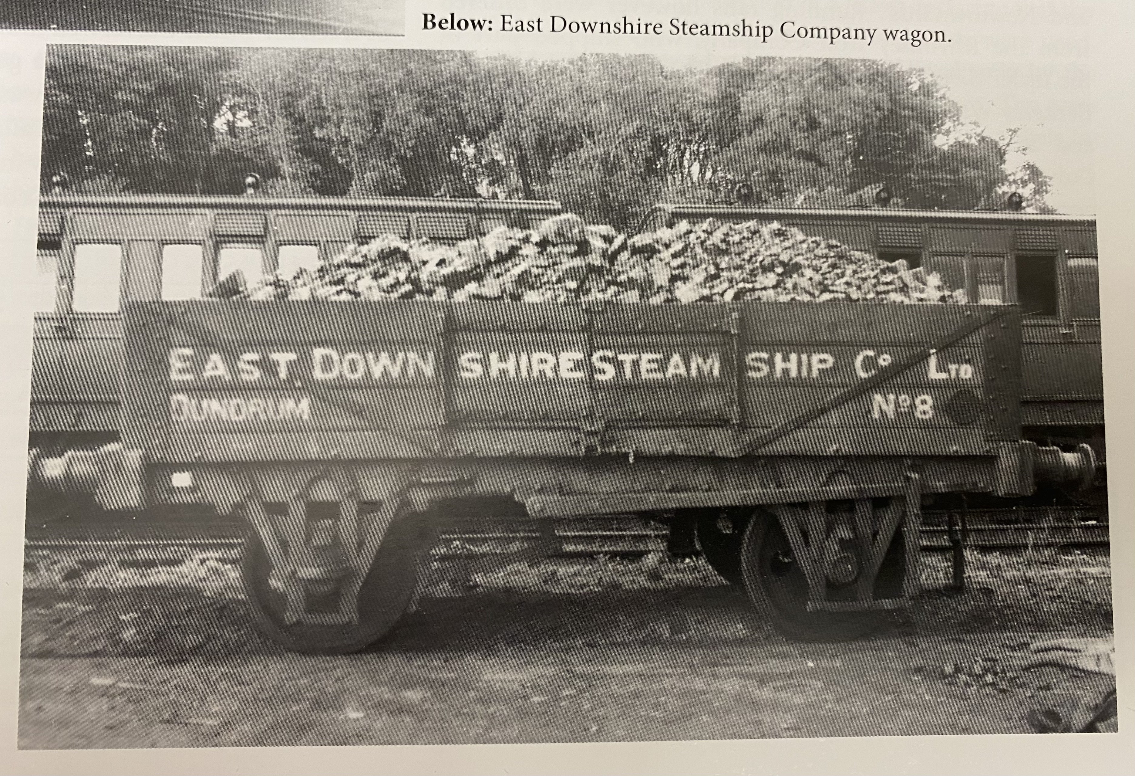
These private owner wagons saw service on the BCDR network, transporting coal landed at Dundrum, County Down. Provincial Models did a nice model of one. (Photo: Demond Coakham) As a distraction from soldering door handles onto BCDR coaches, I did some surgery on one of my Provincial EDSS opens, (Apologies Leslie. Look away now ) aiming to try and nudge the Dapol chassis a little closer to the appearance of the prototype. Starting point - I'd already weathered it a while back. Butchery. Not pretty... but getting better... An MJT wagon compensation etch provided the bits for outside W irons... and bits from the spares box did the rest... And now, back to coaching Alan

- 613 replies
-
- 15
-

-
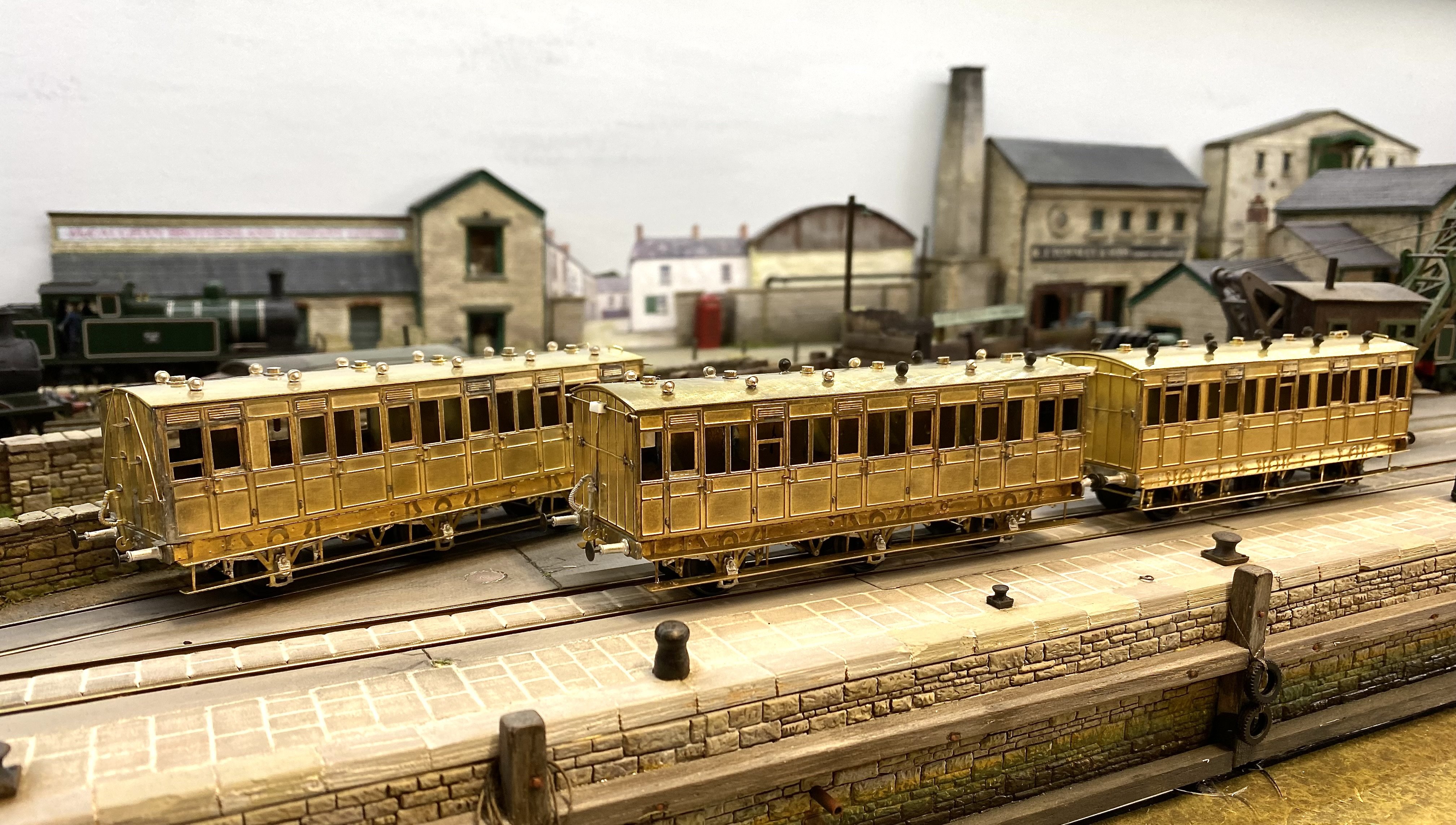
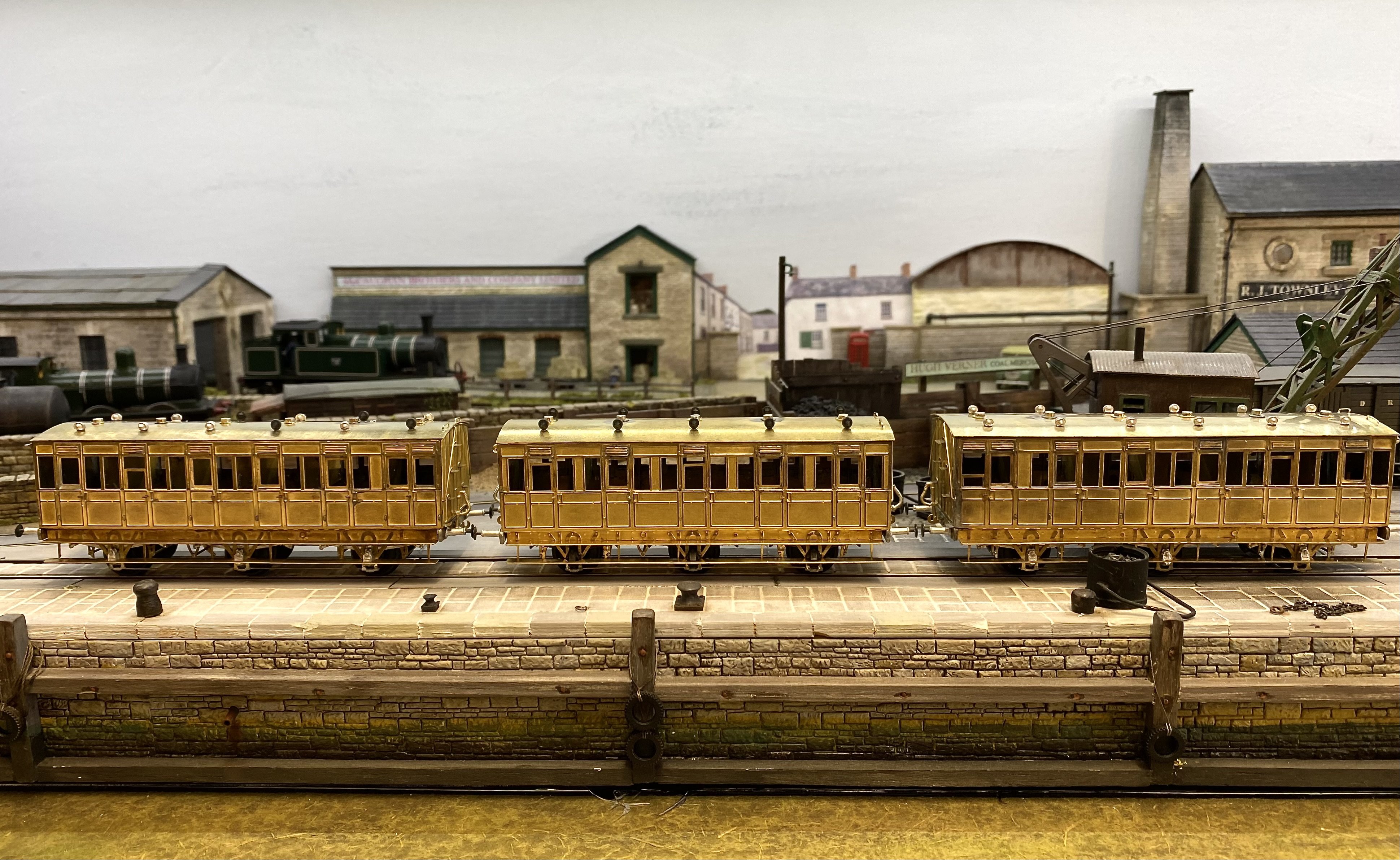
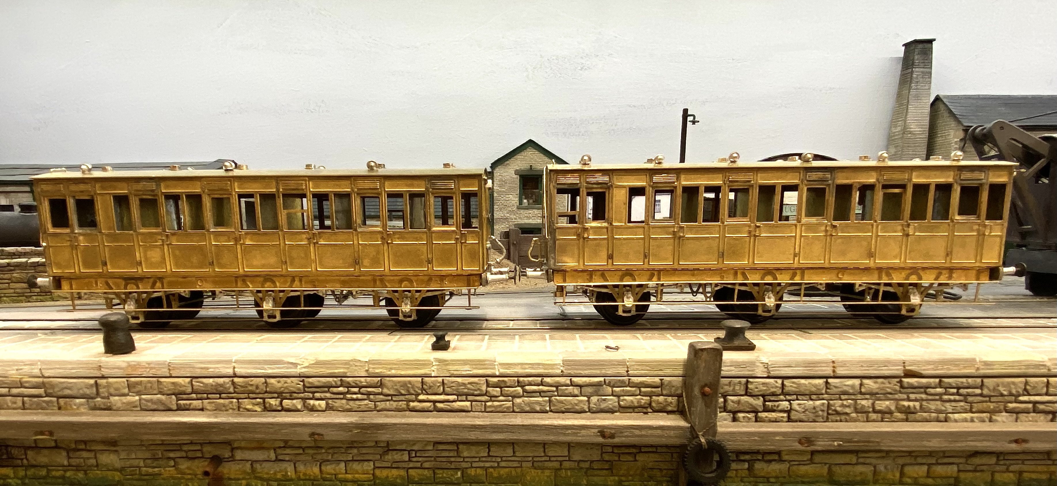
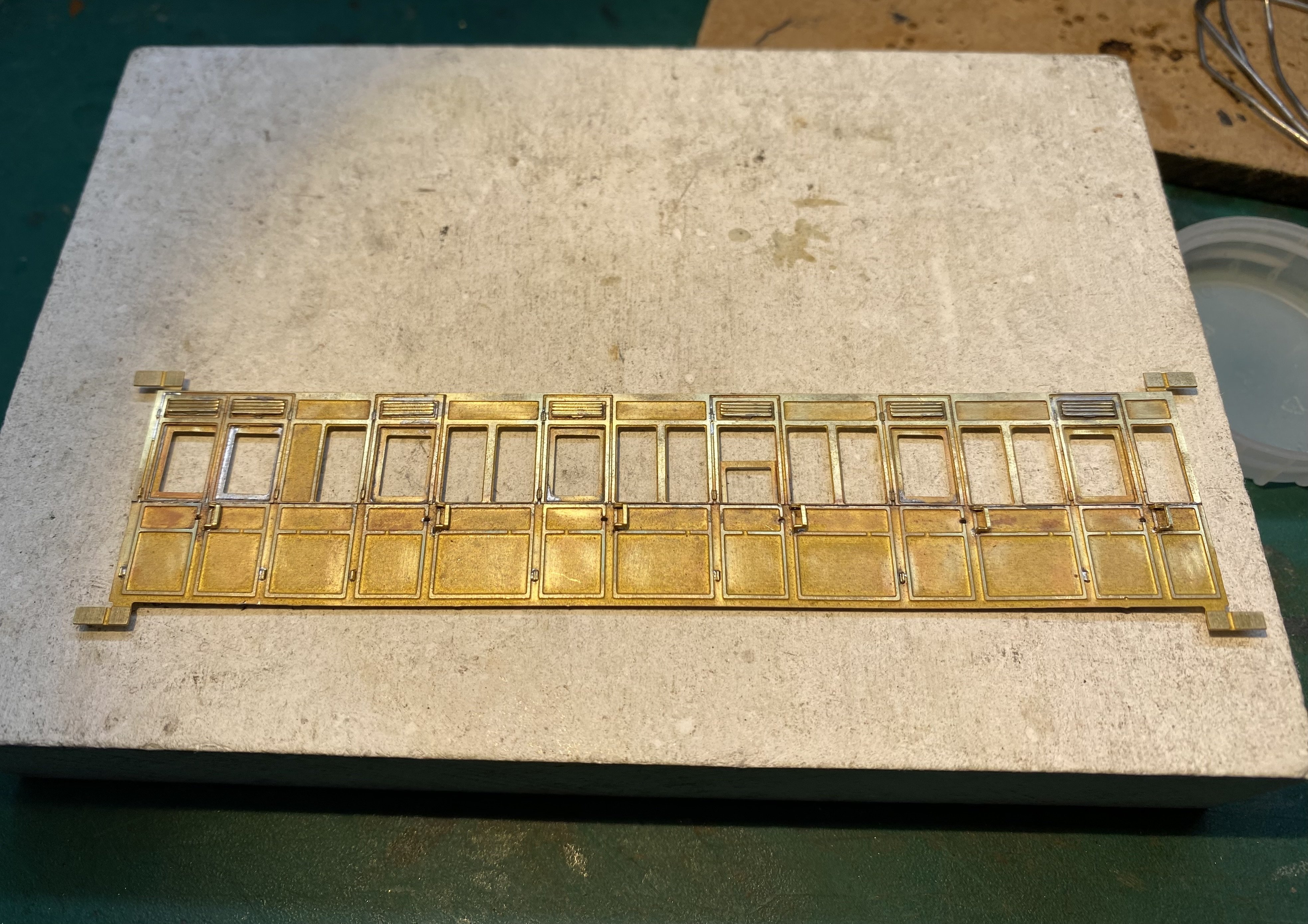
More BCDR coach work. Group portrait in brass... Nearly ready for paint Alan
- 613 replies
-
- 16
-
-

-
Another gem. That weathering is beautifully understated. Spot on!
-
These any good?
-

Clogherhead - A GNR(I) Seaside Terminus
Tullygrainey replied to Patrick Davey's topic in Irish Model Layouts
A masterpiece Patrick. Just keeps getting better! -
That's a very impressive production line John with some very fine modelling in there. I'm not surprised you lose the odd wheel set. I for one I couldn't keep that many balls in the air at once without losing my place eventually
-
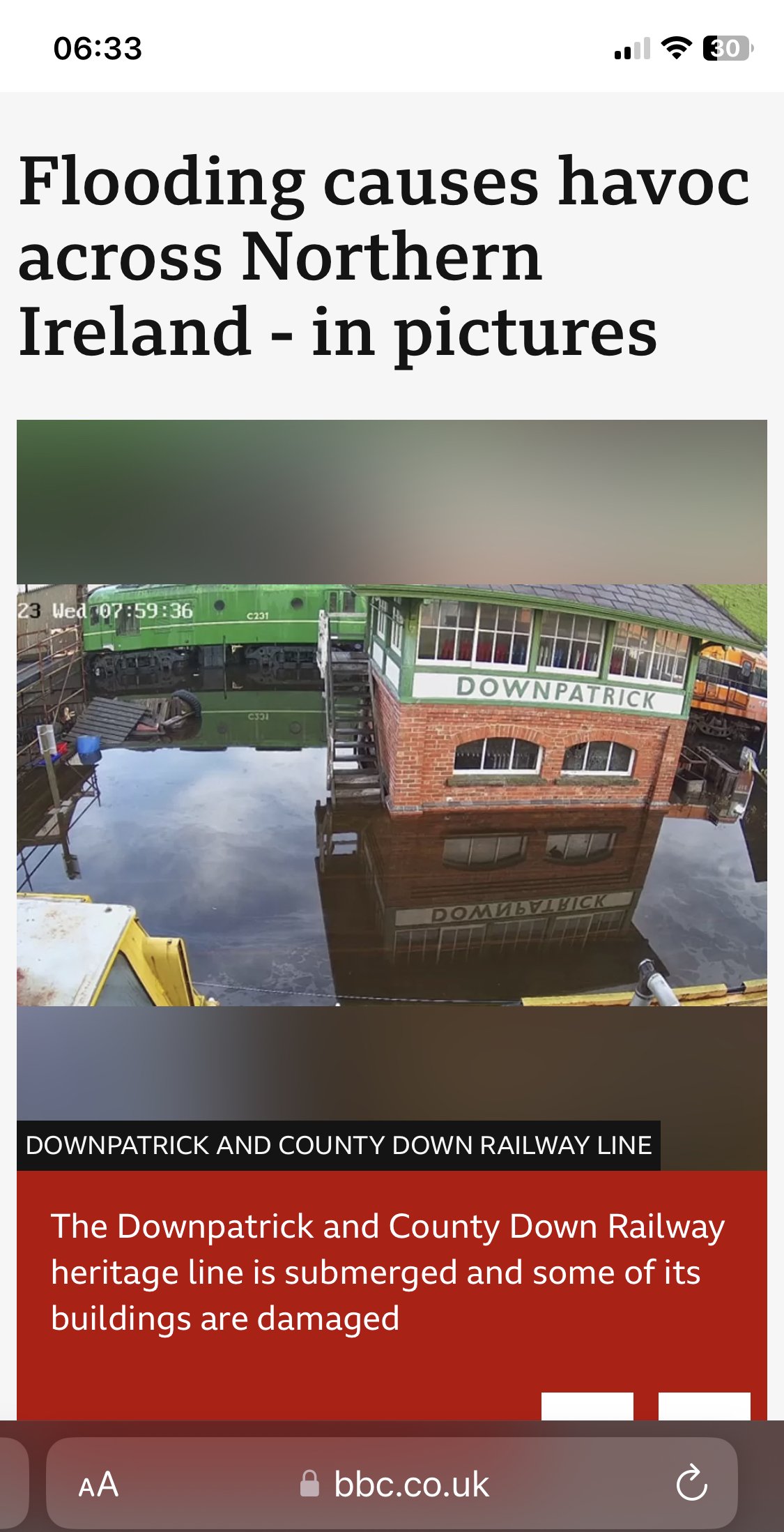
Given the flooding in Downpatrick this week - witness this pic from the BBC website- I hope the damage at DCDR isn't too severe and that 90 hasn't been too badly affected.
-
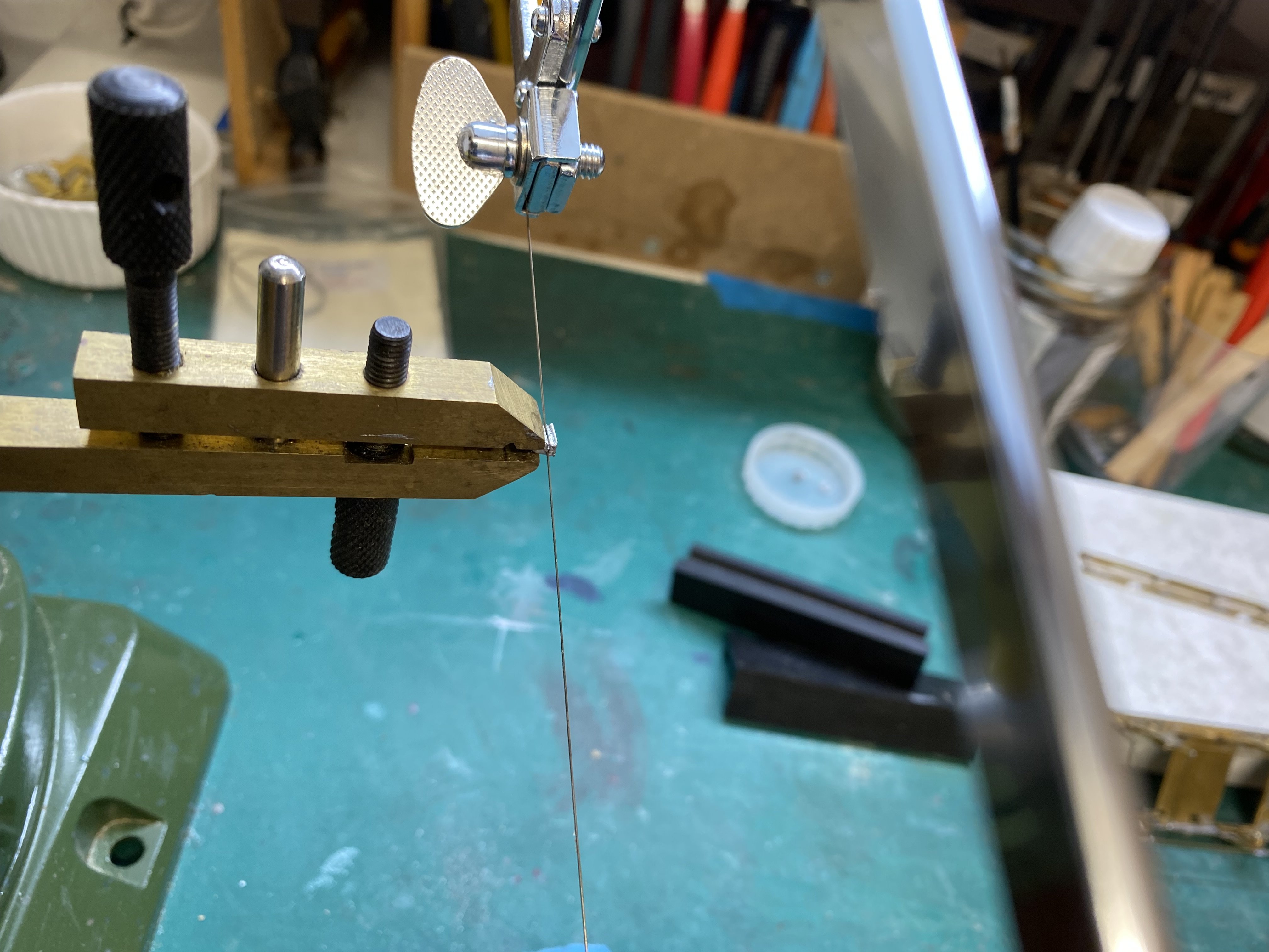
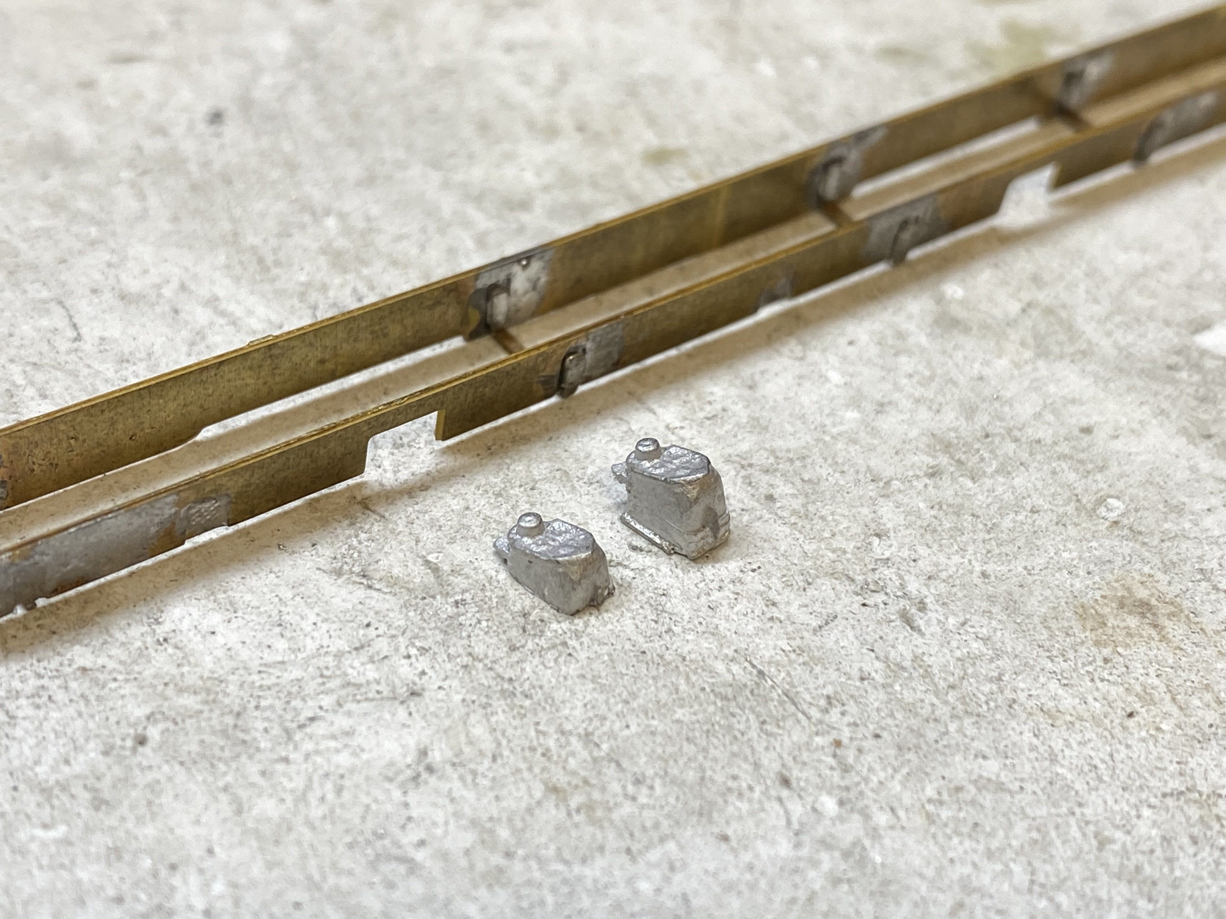
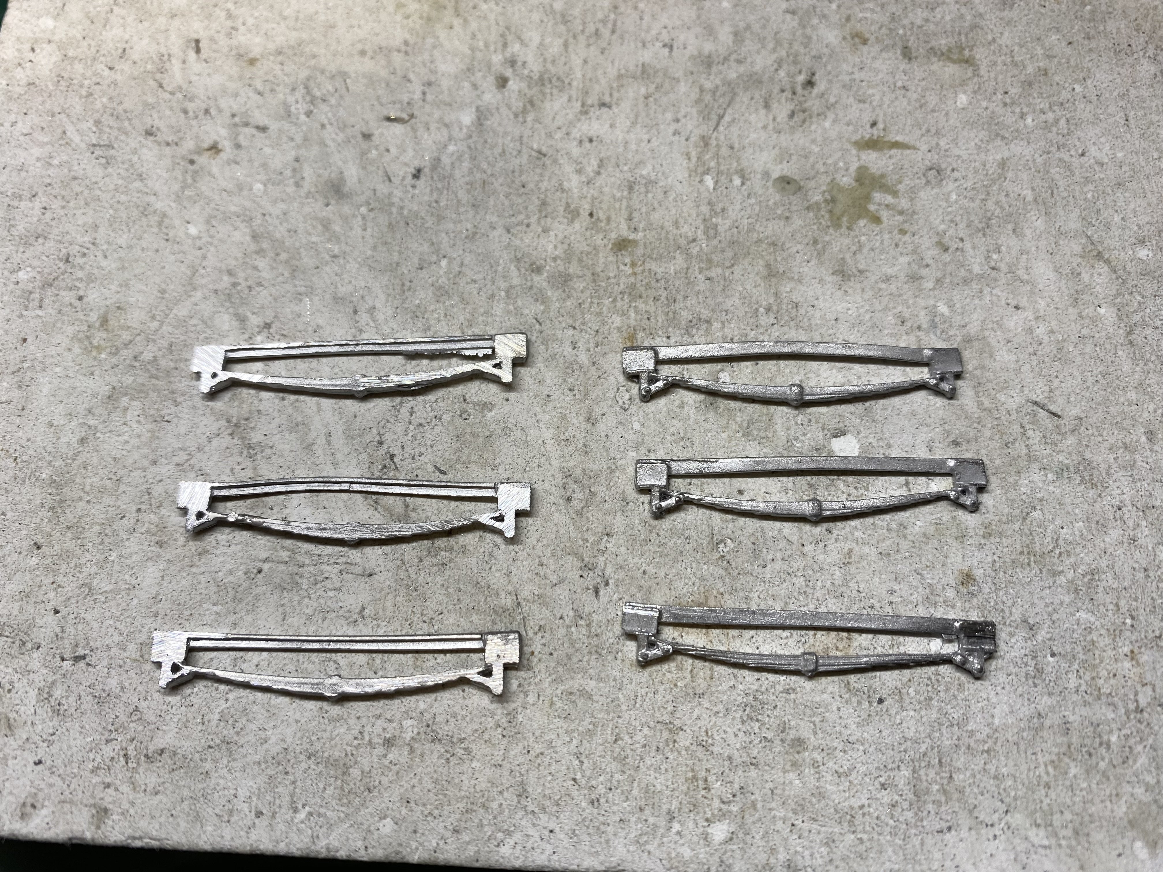
More castings attached to the BCDR coaches. I've managed to vaporise white metal in the past, even with a temperature controlled soldering iron so I bottled out and epoxied them on. MJT 2289: 6'6" Coach springs 2251A: L&Y Axleboxes 2308: 24" Coach/Wagon Buffers A Gibson 4M600: Vacuum pipes (These are brass and were soldered) The axleboxes were the best match I could find, going from prototype photos but they were too thick, front to back, to fit behind the lower step. The piercing saw came to the rescue and did a neat job of slimming them... The spring units also needed slimmed a bit to allow them to slide into place so they were filed down on their backs using a cheap file, now clogged with white metal... With the castings in place the steps could go on... Beginning at last to resemble something you might've seen trundling down to Banllynahinch a while ago. With all the handling, there's a fair bit of tarnish on that brass now which will need removing before any paint goes on. I use Barkeeper's Friend abrasive powder with an old toothbrush. That does a fairly good job of cleaning things up but I wondered if there was a better way. I consulted the Googlesphere on the subject of cleaning brass and came across a recommendation for tomato sauce. (Really!) I tried it on a little bit of scrap tarnished brass and it worked remarkably well but I'm not sure about using it on a whole BCDR Brake Third. Getting the sauce out of all the crevices afterwards might be an even bigger problem and colour-wise, it's not close enough to Crimson Lake to leave it in place. Keeping the sauce for my chips, Alan
- 613 replies
-
- 12
-
-
-
Love the Swilly coach David. Beautifully crisp lines and a credit to your skills (and patience). Good luck with the tank loco. I'm looking forward to seeing that develop. Keep us posted.
-
Clogherhead - A GNR(I) Seaside Terminus
Tullygrainey replied to Patrick Davey's topic in Irish Model Layouts
Mighty! Just exudes GNRI. Nice one Patrick -
Clogherhead - A GNR(I) Seaside Terminus
Tullygrainey replied to Patrick Davey's topic in Irish Model Layouts
A gem, Patrick. Lovely work. -
Clogherhead - A GNR(I) Seaside Terminus
Tullygrainey replied to Patrick Davey's topic in Irish Model Layouts
Lovely stuff. Following this with interest Patrick. It's great to have a window on your work. -
Wonderful!
-
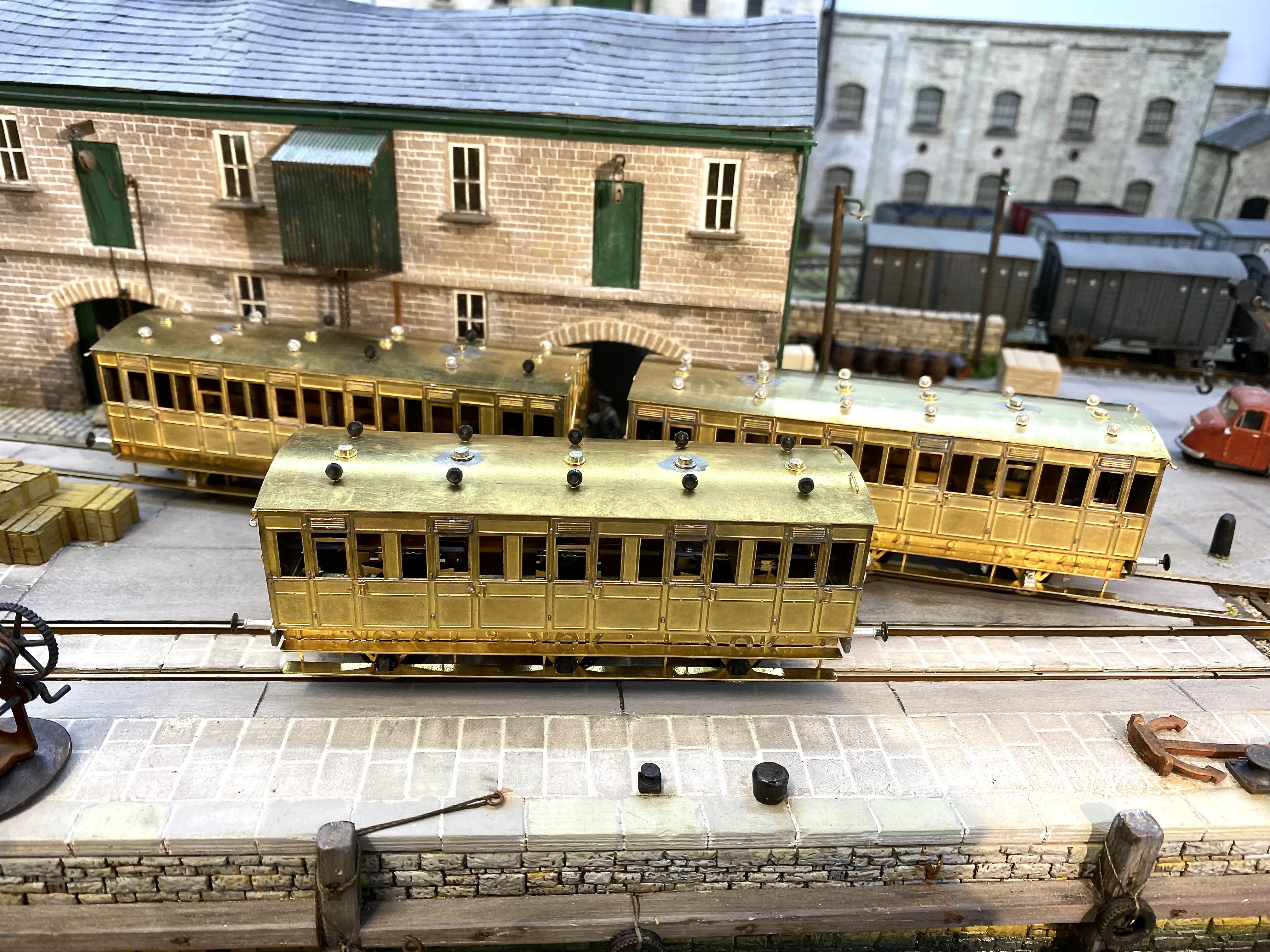
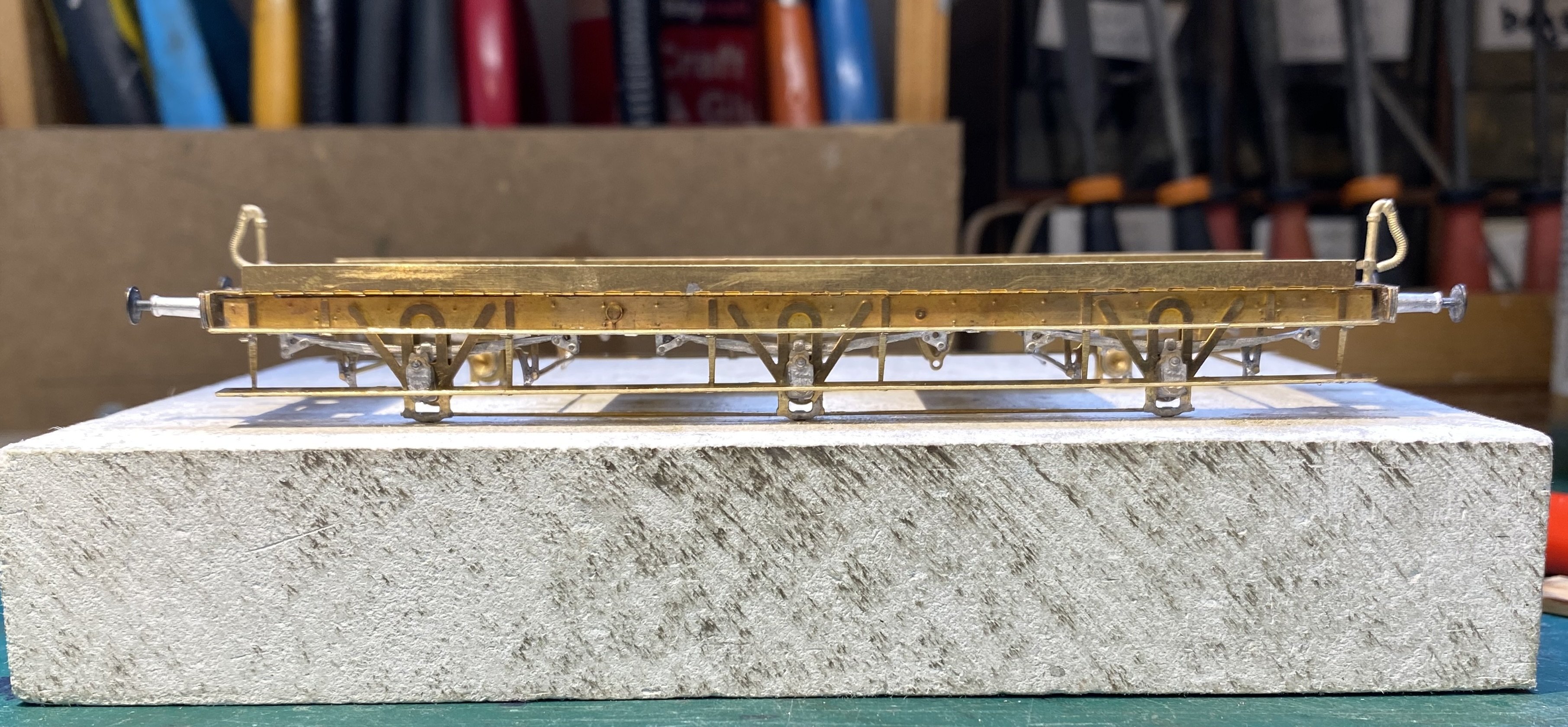
Progress on the BCDR coaches has been a bit sporadic lately. Having started out with etches only, I've now gathered castings for springs, buffers, vents, axle boxes and vacuum pipes from various sources. I've also started on the second coach, hoping to get both to the painting stage so they can be done together. Having said that, a third one, a 5 compartment 3rd on order from Mousa Models, arrived sooner than expected, a nice surprise so it's in the queue now too. There's a lot of repetitive work in coach building which for sanity I tackle in short bursts. Each of the brake thirds has 12 door handles, 12 grab handles, 14 drop lights, 14 ventilation panels ... you get the picture. All belong in the 'little things sent to try us' category. This is the current state of play with the second kit. The 12 torpedo vents are white metal castings from Alan Gibson(4M722) and the 6 lamp vents are improvised from 10BA brass washers and cheesehead bolts with the slots filled with solder. Four of these are trimmed off flush on the underside of the roof and two screw into captive nuts in cross members to hold the roof in place. Rattling along in 3rd class, Alan
- 613 replies
-
- 15
-
-
-
You're definitely not alone Patrick. I imagine we've all confronted this perfection-vs-the-time-required dilemma in some shape or form at some stage. The deciding factor will be whether you can live with what you end up doing or whether it still bugs you months later. My most recent encounter involved making a mess of a paint job (as I am wont to do), spending time trying to fix it but eventually rubbing out and starting again. As a compromise between accuracy and the time required to get there, would it be possible to clad your stone quoins (or some plain, appropriately shaped plasticard) with a suitable shade of brick paper? The lack of 3D relief might not be evident, given that the rest of your building has plenty of texture. Cheers, Alan
-
That medal you earned for persevering with the AJ couplings… I think we should add a bar to that
-
Shame. Ah well, as long as it moves
-
Perfectly realised. A coherent and believable scene with real atmosphere. Lovely stuff David. You may have already posted about this but did you manage to get the crane shuttle module working?
-
Clogherhead - A GNR(I) Seaside Terminus
Tullygrainey replied to Patrick Davey's topic in Irish Model Layouts
Not to mention the oil and hydraulic fluid leaking from that old JCB -
The brakevan looks well. You deserve a medal for your perseverance with those AJs. I think I’d have given up long ago. But it’s clearly been worth all the effort.
-
Excellent. A great layout emerging there.
-
Clogherhead - A GNR(I) Seaside Terminus
Tullygrainey replied to Patrick Davey's topic in Irish Model Layouts
Lovely work Patrick. There's probably a joke in here about The Sandman and working at 2am. But I won't make it -
Lovely detail and finish. A real charmer. If you hadn't mentioned the scale, I would have assumed it WAS 7mm!
-
That's very useful. Thank you Angus. The clearest photo I've seen was apparently taken in 1951 just before withdrawal, so it would be reasonable to suppose that as you say, there might've been a few changes over the course of 70 odd years! Regards Alan
-
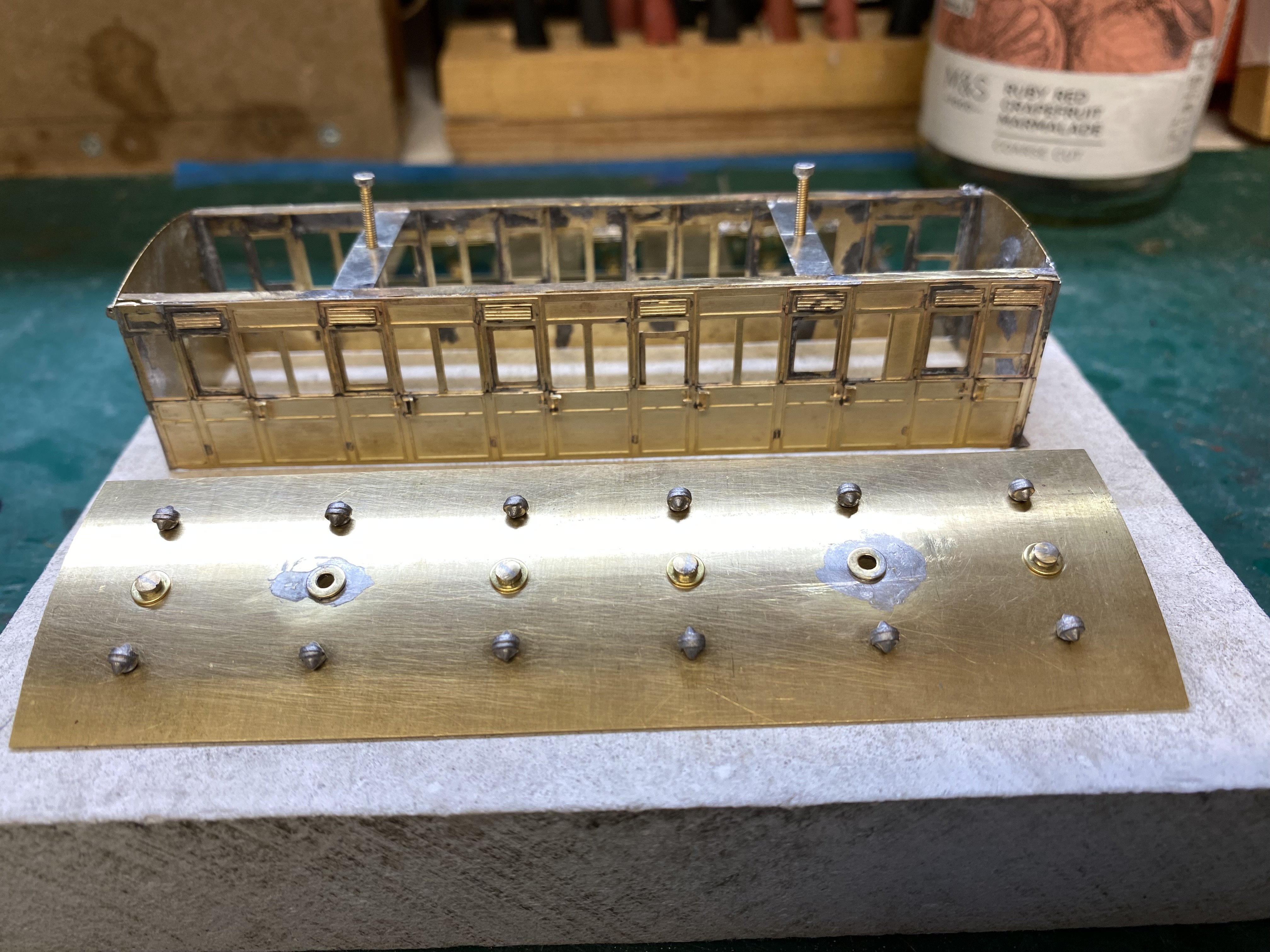
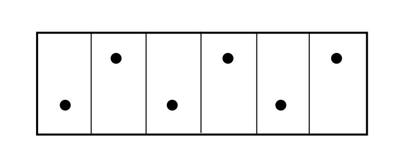
A quick question which I hope someone can shed some light on. The coach I'm currently building is an Oldbury Brake Third, built around 1880; It has 6 compartments in total - 5 passenger compartments and one for the guard. In all the photos I can find, only 3 torpedo vents seem to be visible on the roof. Is it possible that there were 3 on each side, alternating thus? Cheers Alan