Sean
-
Posts
890 -
Joined
-
Last visited
-
Days Won
3
Content Type
Profiles
Forums
Events
Gallery
Blogs
Everything posted by Sean
-
Thats a lovely piece WRENN
-
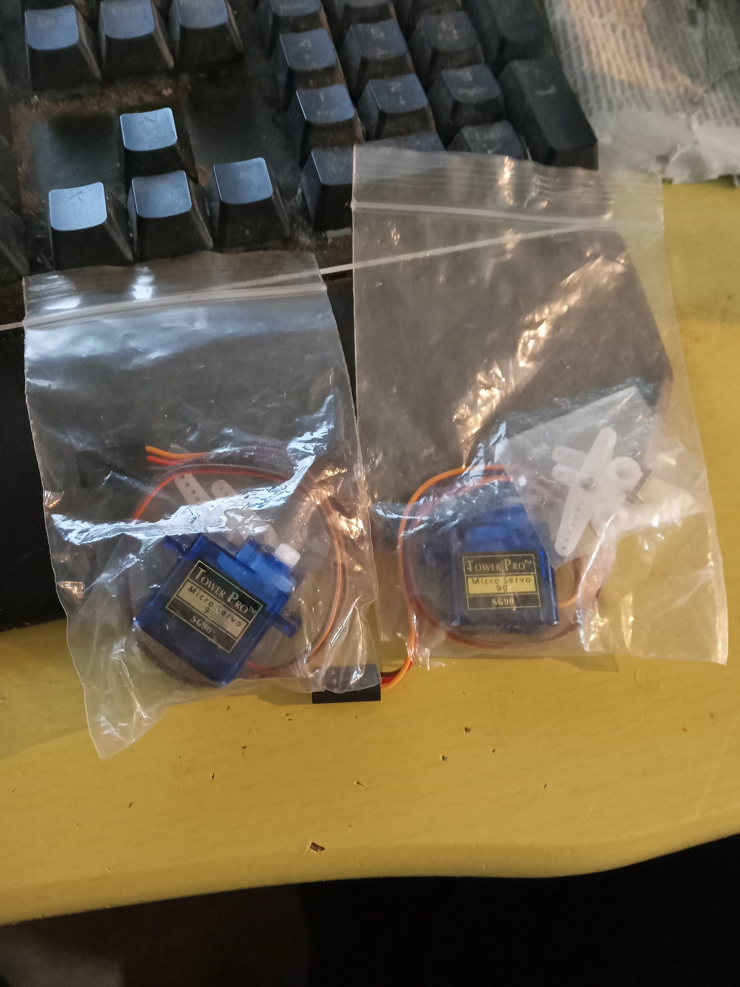
lol i only found them by pure chance as well as i am moving the layout at the moment and just caught the line in the plastic with my eye as i was setting them back up. I actually bought some earlier in the week. but im planning on buying some more now.
-
when did the coloured signals start and when did they become more widespread? i wouldnt mind trying the disused semaphore alongside a working coloured but im worried that may be slightly too modern looking for my rural backwater theme that ive got going.
-
looking for some advice on signalling my layout which is set in the IR era. were semaphores still used during this period or had anything moved onto "traffic light" signals like those used today.. i prefer the idea of lit signals so i can incorporate them into the computerised side of the layout.... would it just typically of been a single signal to signal the approach to the station or would there have been further signals to signal the sidings? Id also like to add a few lineside signs leaving the station such as a speed limit but i also do not really know where these typically would have been placed or which ones would be needed to accurately model such a thing. any help is appreciated seah

-
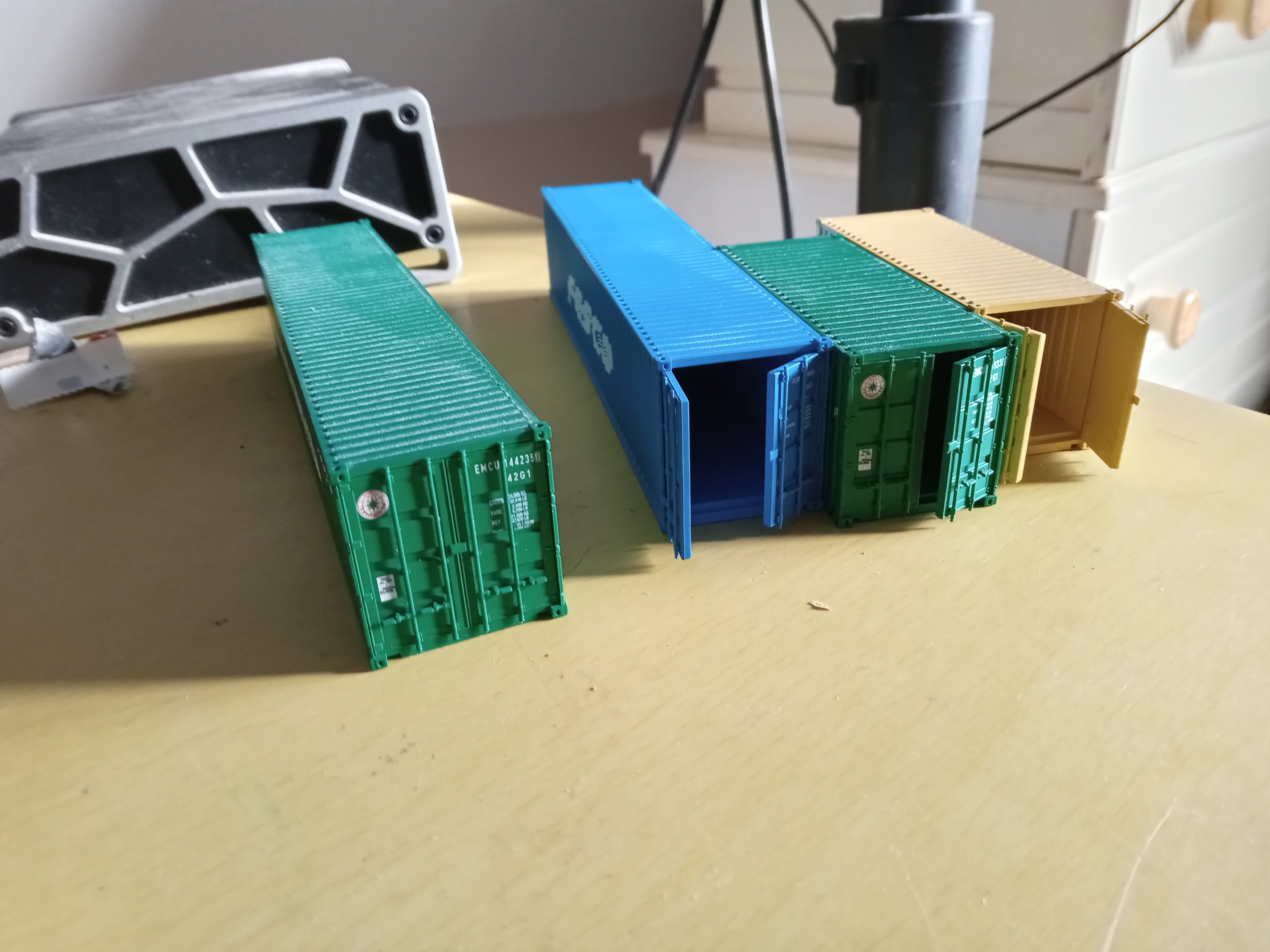
Just noticed that these Hornby containers have moving doors. They kept that well hidden!
-
Didnt you know its bad form to comment on their age
-
That's great to know, placed a hattons order last night so am in prayer mode that it lands safely.
-
nice, CMD+SHIFT+4 does the same thing on a mac, screenshots to desktop.
-
Finally a breakthrough as i have hit a configuration that works! the ethernet port is a godsend, if i just want to basically play trains i can now just start one of the apps on my phone and connect so its up and running instantaneously without the rigmarole of starting jmri/roc or even turning on a pc. im still getting the same error message that was crashing out the usb link however it is totally ignored by a tcp connection so im assuming its coming in over the z21 network and rocrail doesnt know how to parse whatever it is, as usual the error messages were very cryptic. not to worry as i was able to spend about an hour driving around the A class with an 071 sound file, no crashes, no command station dropout. JMRI is not needed now so it will not really be used except for decoder programming as the decoder xml files are supposed to be compatible with roc. next step will be running 2 nextgen processes from a single computer, that should be trivial enough. once it works plenty of solutions are available for routing audio to different outputs on windows. as I see there are a few options from here. I can spend the bones of 700 euro getting ESU chips for my growing fleet (lul).... I can keep going with the bluetooth which is working however i need to source some super capacitors before its gonna work properly and the design needs slimming down for sure to get into baby GM's Ill keep going with that for now but progress is slow. there is also another option i want to explore which would be putting a pair of speakers on the layout and somehow tracking the locos as they drive across it. if that was possible its should be easy to use that data within audio software to create a dynamic sound scape within the base board. one could also add an atmos track and sounds for other static things on the layout that would usually never get sound. it could surely be done with block detection however there would need to be a lot of blocks to ensure accurate tracking. thats one for another night though LOL I could also stick a fat subwoofer to the base of the layout so it vibrates as trains pass on it....... edit: jaysus the tracking technology exists. just imagine if he was waving around model trains instead of bottles lol, IF this works its going to become hilariously technical. above video tells me its going to work, I need to go to bed or im going to be juggling bottles before long!
-
nah its some old atom netbook from that weird point when they tried to make laptops as tiny and unergonomical as possible so it has little other tangible use lol
-
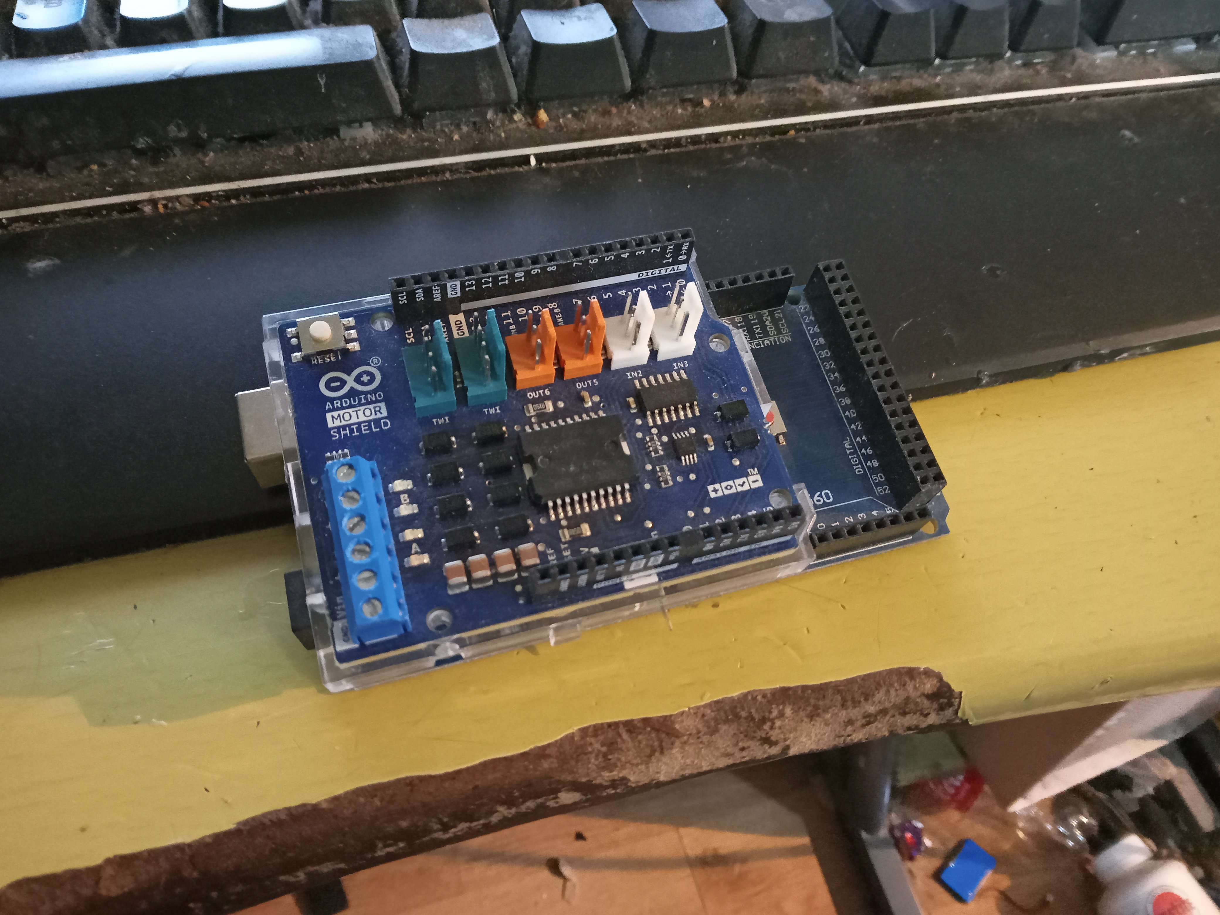
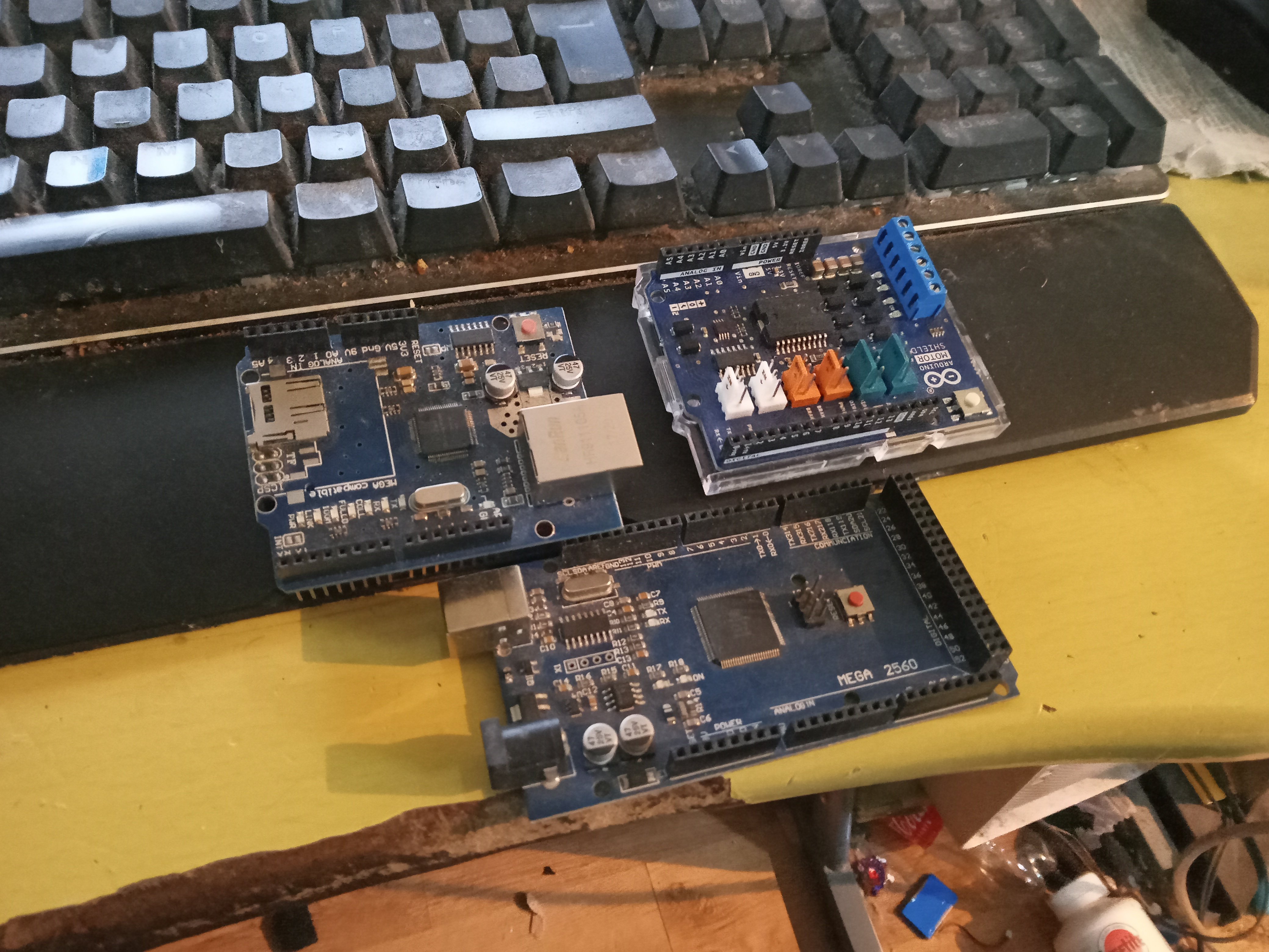
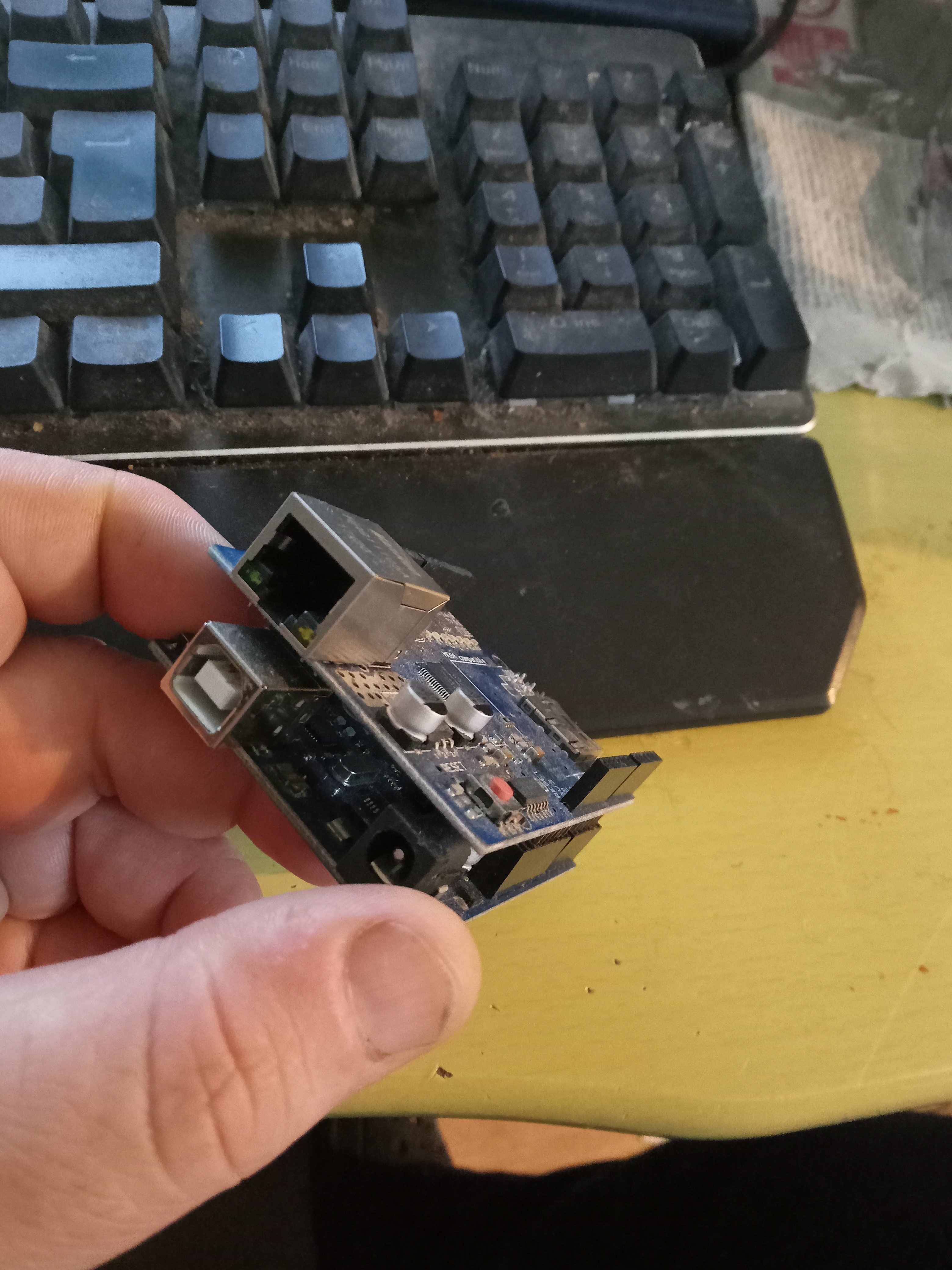
A pretty simple upgrade. Get base station Remove motor shield Plug all the shields back in. ethernet goes first as it has additional communication pins Motor shield on top to retain access to power terminals. Now we have a standalone base station. No pc required.
-
Spent a good few hours trying to make rocrail and jmri talk to eachother via loconet or some other protocol with the thinking jmri could be a stable base station and rocrail could do all the throttle action (and nextgen) Alas after much hair pulling it wasn't to be however..... I did finally come across my missing box of Arduino stuff. Finally my ethernet shield has surfaced! This will do two things, firstly I can say goodbye to the laptop altogether now and control the base station directly from a phone or tablet. Way more convenient. Secondly I can ditch the buggy USB connection in rocrail and connect via this port which uses its own set of libraries so I'm confident it should work more reliably and that will be the new path to sound. I suspect the buggy behaviour might come from it being a clone Arduino with the cheaper usb chipset so it will be good to see how it behaves over Ethernet. Also Point motors!
-
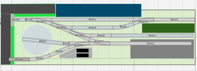
new year new layout 1990s container terminal and tmd
Sean replied to Sean's topic in Irish Model Layouts
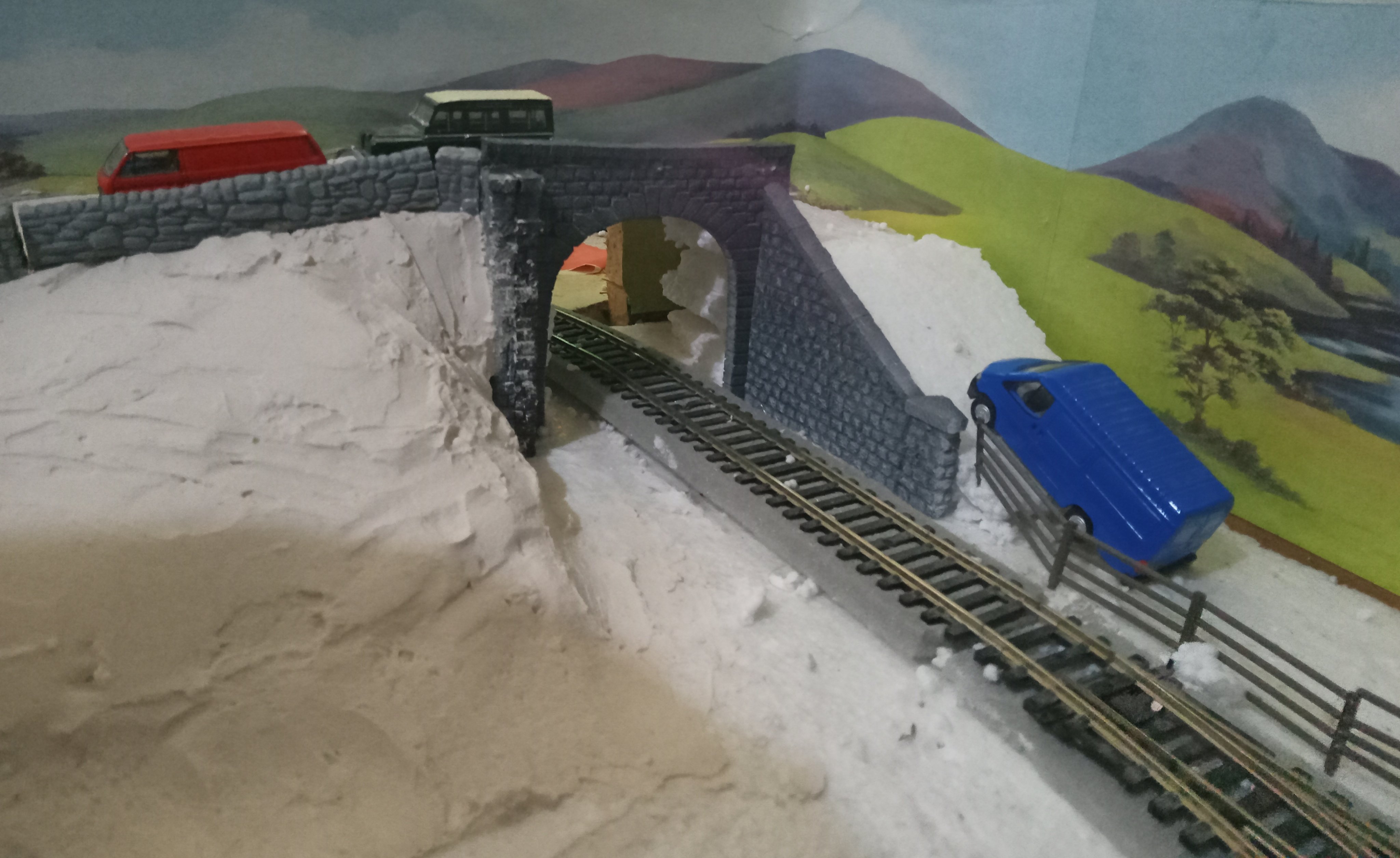
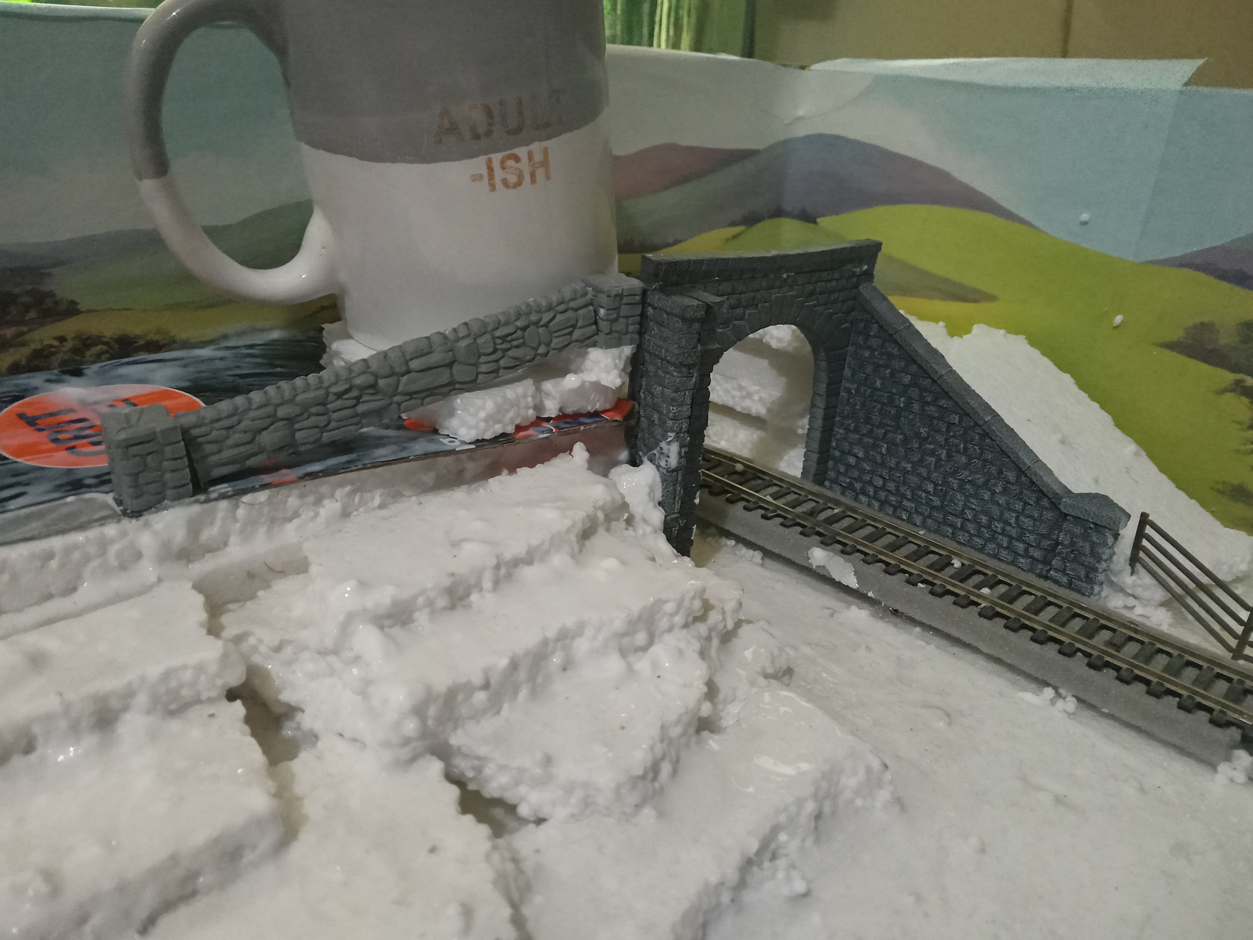
I am definitely considering that however in hindsight i have not left myself enough space before reaching the platform so a little bit of a compromise will have to be reached. thats the only part left on the baseboard that i havent actually surfaced with filler just yet. so it does look slightly steeper than the finished product will be when its done. The sort of overpass im looking to create is similar to like the one at Arklow. which is quite a steep climb condensed into a fairly narrow space and over a hump ontop. in the end this will be a bit steeper but im hoping it should pass in model format once the severity of the start of the hill is taken out with filler. -
nothing wrong with the silverfox stuff per se if thats what your into. same as we recently had this debate on wether another gm with old tooling would sell or not. I still give the argument of so what if the thing isnt quite 100% up to modern par and standards. if thats what is available people will buy it and hopefully the manufacturers will be able to be a little more competitive due to not having to R&D a completely fresh product. at least models of this stock actually exist rather then infinite what ifs and a very large percentage of irish diesel stock has been modelled at this point in one form or another. in fairness us irish modellers are SPOILED with the stock that is available to us. in production or not. Look at the shite a lot of british or continental modellers have to put up with with the same tooling issued for years and years amid rising prices. imagine buying this yoke in 2022 - lima era tooling and a big fat detail stealing and easily pierced sticker for an excuse of a paint job. Imagine if PM did that with the enterprise livery 201 and put it out for 100 euros..... youd have some younger modellers absolutely delighted to be able to get into things more affordably but the rivet counters would be soiling themselves in disgust. if that younger market isnt grown out then isnt there going to be a hell of a lot less people interested in model trains some 20 years from now when all that is running around is DMU's and a lot of the youth wont have ever actually seen anything locomotive hauled in the flesh....... When i was about 10 the GM era was ending and i had never seen a 201 class with where i lived, i have seen them maybe 4-5 times ever in the flesh as I live in DMU land and would have to go out of my way to see one now. most kids getting into things now would the same unless they specifically lived near one of the few remaining freight corridors or on the dublin-cork route. all they will see is DMU's and it might not spark the same excitement as with past generations of enthusiasts. now im not saying id buy silverfox given the market thats there right now, however more than a few times i have considered there shunters and coaching stock. since kit building would have been way out of the realms of what i was capable of as a teen and MM stuff didnt really exist I did actually aspire to build a fleet of these class 66's. looks like i didnt miss much as the exact same ones are still available now...... edit:moderator....
-
there will soon be a fee payable in order to allow you the previllage to pay the fees
-
ah sweet, one of the easiest forms of pitch shifting is a slight change of tempo, which would translate to a slight change in rpm for our uses. that would both solve the issue of possible cancellation and create the slight rpm overlap i mentioned earlier.(think like between 1-10rpm of a difference. minute stuff mechanically but enough for the ear to pick up on) You are after getting me very curious about this now and im after finding somthing in the manual that MIGHT just explain it. as the speakers arent usually marked it could be easily overlooked. this makes the most sense to me as if the speakers were wired with opposing polarity one is creating a positive pressure wave whilst the other is creating a negative one and vice versa. as the sound waves are identical this is where we would see phase related issues crop up and cancellation would be most apparent when both speakers are equidistant from the listeners ear, but less apparent if heard side on it works the same when recording a snare drum for example in a recording studio with a microphone set on the top and bottom of the snare, as the micrphones are facing one another we get the same phenomena of one mic recording a positive wave whilst the other one records the negative wave, usually theres a button on the console or within the recording software itself to reverse the polarity or else the waveform can be later flipped in software. its also important to measure the distance from the microphone to the drum head as the sound has to reach both micrphones at an identical time or else a slight audible delay is recorded and phase flipping will not work.
-
looks like that post detailed separating lights and markers on 121 class, sorry for any confusion.
-
i used them from uk when parcel motel stopped northern ireland operations. got a disproportionately large customs bill with absolutely zero means to appeal and havent used it at all since.
-
in my mind the sounds would sum and be too insignificant to cause any sort of perceptible phasing, however it wouldnt surprise me either, perhaps it might come down to the sound getting thrown everywhere without any sort of enclosure as opposed to it being more directional if coming from an enclosure. yep had a think about that, even if you started the engines seperately as soon as you notch the engine the next set of wavs are going to be triggered at the exact same time bringing it all into sync, altering the wavs of one loco to loop in at a different point would solve that but it still wouldnt be entirely realistic as the 2 engines would ALWAYS still be exactly in sync just firing at different points. in real life no 2 engines can be exactly the same off the factory floor and that becomes even more apparent as components wear and they will run at marginally different rpm's and the sound will overlap in and out of itself. particularly as rpm changes. theres a certain randomness in timbre between 2 running motors that would just be difficult to fully capture within a piece of software looping wavs on cue. you would nearly want to have 2 entirely different recordings of the same prime mover type and somehow randomly delay one of them by a random 1-100ms interval at a notch change, I dont know if ESU even know how to do stuff like that yet lol. a DAW on the pc could do it with nextgen running but feck thats even more moving parts that im not going to even consider investigating my thinking was i could have 2 nextgen files running to a single bluetooth module in mono with a mover panned to each speaker and a speaker in each logo. no good unless all the above aforementioned stuff is first solved.
-
I dont think you would have much of a problem with destructive phasing as the engine tone oscillates rather than sitting at one specific frequency. the sound of the 2 prime movers would not be in sync if the motors started at different times also so the 2 sources should harmonise into one perceptually. any losses in fidelity due to phase would probably only apply if sitting in between the 2 speakers however these losses would also be experienced in the real world also, particularly if walking around 2 large running prime movers, you will always hear some audible anomalies between the 2 engines. issues with phase in the real world in my experience has mostly been confined to recording with a stereo pair of microphones or in large line array PA systems in large venues where the sound has to actually travel a distance before it gets to the audience who will be hearing the performance from multiple sound sources and phase or delay can occur due to the same sound reaching them at different times from different speakers. it is not something i had ever considered in speaker design all that much before seeing it demonstrated on that video a few weeks ago with the train speaker although even then i found its importance to be limited as the guy took care of it quite easily and designing any sort of speaker cabinet at all really tends to seperate the front and back of the cone, with the back sound being completley different once it finally bounces around and gets out the port on the back of the speaker. you see thats the thing. my hardware (dccpp) runs under both however the rocrail version seems very buggy and the command station routinely crashes leaving a loco running with throttle applied until rocrail is restarted which leaves me stuck on JMRI as that is going to cause an expensive accident on my end to end before long and with the prices of this rolling stock that will make me very sad. when my next paycheck arrives im very tempted to just order the z21 multimaus off ebay de and run nextgen via that, i genuinely dont think the nextgen dev has intended for jmri or rr compatibility it just so happens to be a bonus that they do work, the fact that my z21 protocol apps are connecting to jmri but not sending or recieving throttle commands has me optimistic too, theres a few different z21 protocols available with jmri depending on the age of said z21 equipment so it may still be down to giving it a bit of a tweak till it works, sadly there is no jmri forum to ask one and the documentation is a bit sparse
-
if the developer of nextgen used literally any other protocol except for z21 this would be a lot easier for jmri lol. is it normal to only use a single sound decoder when consisting? obviously itd save 100 quid but i feel like a certain characteristic of hearing 2 engines running together would be lost with only one speaker/engine. edit: JMRI does actually list multimaus as supported so maybe i simply need to look a little closer. edit2:my z21 app is now connecting to jmri but nothing works yet, this is very promising.
-
VID20220420202842.mp4 Drive hold working on a lokpilot with a JMRI virtual sound decoder! not the best of videos but you get the idea. note that the function is tied to the headlight for testing purposes. @murphaphit seems that drivehold is actually a feature of the lokpilot as well as the loksound. when i did a bit of digging into the logical functions in decoderpro i was greeted with these options so theres a bit more under the hood than we think in these lower end chips, no reason it shouldnt also work on nextgen too as its actually seperate to the sound suite and works just the same as if there was no sound at all. the 201 is also done and works although its not perfect and i really needed to take some time away from it before getting back to it as the keep alive was a bit of a head melter. will upload a video of that soon i still need a windows pc to run nextgen on so im at the mercy of whenever i can borrow the laptop again. rocrail and nextgen wont run on the same pc either(bug)so that adds even more complexity lol. (im considering using some virtual machines but thats getting super advanced.) at this point im not sure if ill use rocrail or JMRI both currently have their pitfalls and neither are easily allowing me to stream audio to multiple different outputs. nextgen seems to be way better than the jmri solution however on the flip side rocrail is not the most stable using my setup as there are a lot of moving parts and the arduino itself crashes regularly. nexgen within JMRI would be the stuff of dreams although i dont think that is possible at the moment. im maybe a little tempted to get the cheapest z21 i can get my hands on to run nextgen this way but i am a big fan of JMRI so we shall see. porting prime mover sounds into JMRI seems to be a fairly trivial process once i have decent source files ready to go. perhaps someone on the JMRI community would be interested in modifying the sound decoder for multiple outs. in my head it would be easy but i dont know a line of java lol. all that being said im still running everything off the linux netbook so i need to get around to building a proper pc for this soon anyway from the parts pile. all in good time though.
-
new year new layout 1990s container terminal and tmd
Sean replied to Sean's topic in Irish Model Layouts
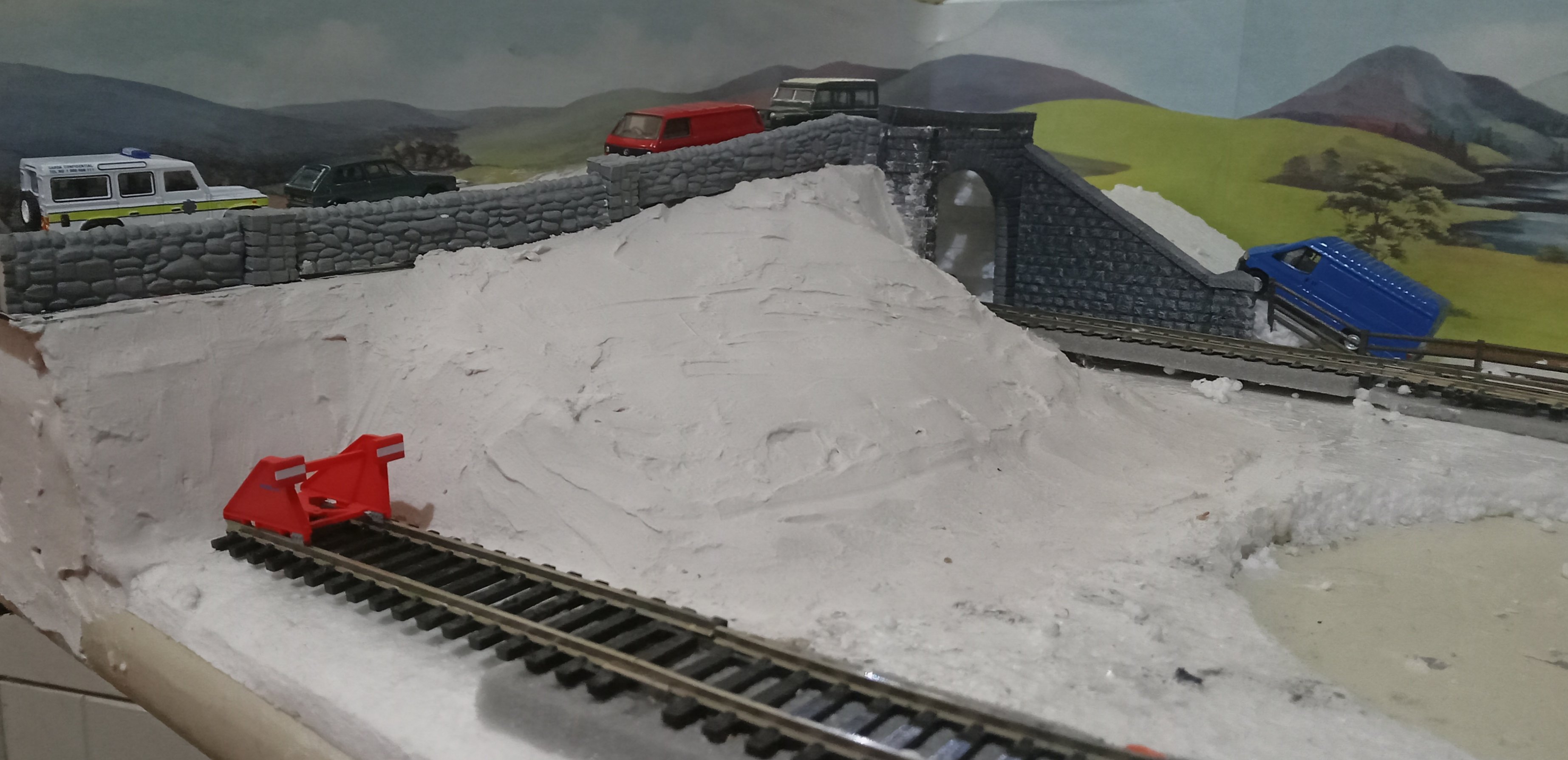
A few hours later....
-
new year new layout 1990s container terminal and tmd
Sean replied to Sean's topic in Irish Model Layouts
Some more construction was definitely needed so filler had to wait. The wall now marks the slope of the incline coming upto the bridge. Not sure how it's going to turn out around the retaining column just yet. Trying to make it not too steep as I don't want a overpass wall blocking the trainspotters view but I also want it to be a rolling embankment where it does stretch down into the yard so I'm probably just gonna wing it and so how it goes. Maybe some rock face will be there by the end of it. On the other side I'm cheating and the bank is lower than the retaining wall so it just looks like a standard wall for the road.
-
Wexford Model Railway Club - Easter Layout Exhibition - 17/18 April
Sean replied to Noel's topic in What's On?
Excellent news! 5 of your beet doubles are high up on my shopping list as soon as funds allow once more.