Tullygrainey
-
Posts
934 -
Joined
-
Last visited
-
Days Won
55
Content Type
Profiles
Forums
Events
Gallery
Blogs
Store
Community Map
Everything posted by Tullygrainey
-
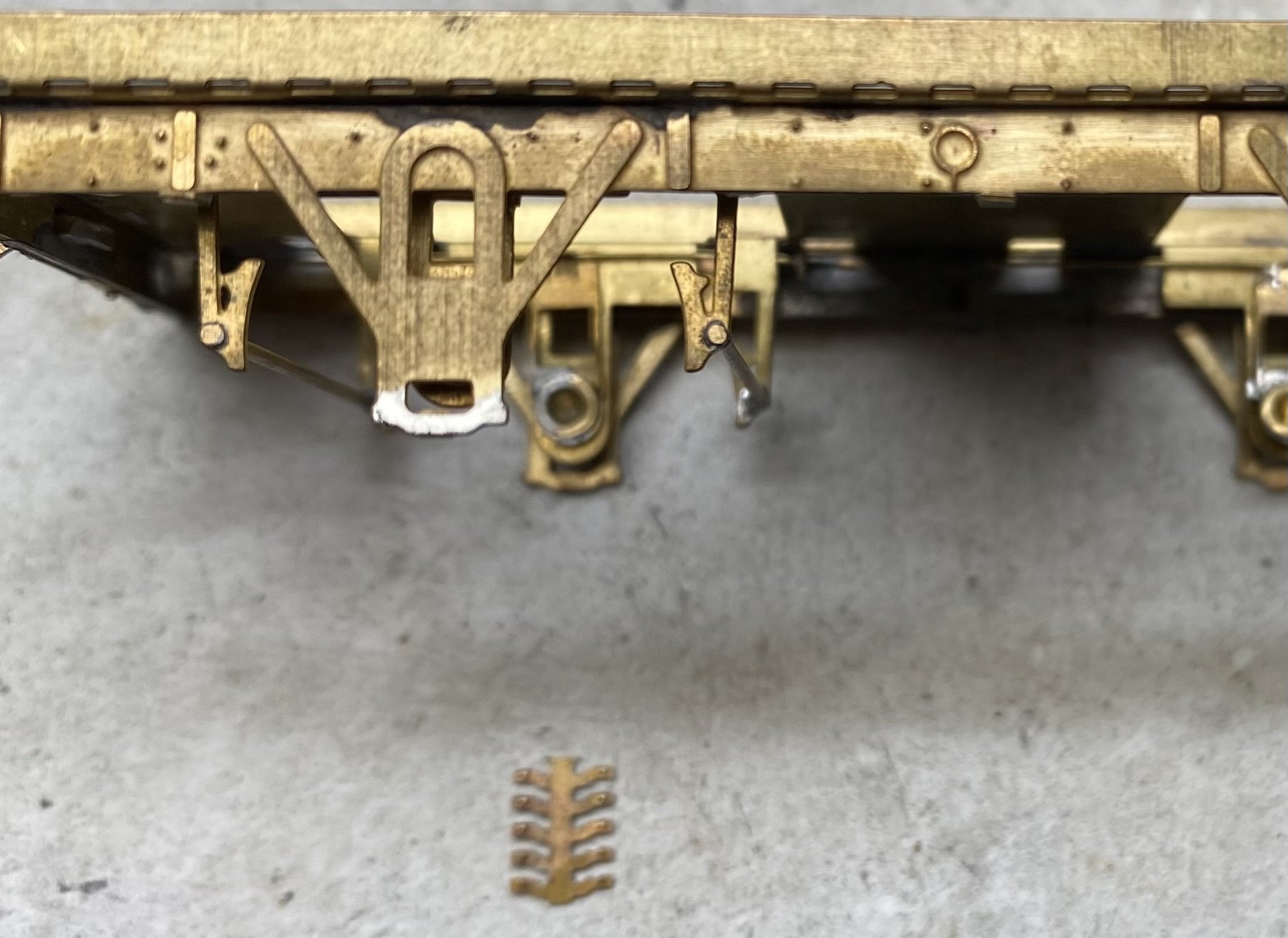
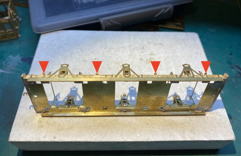
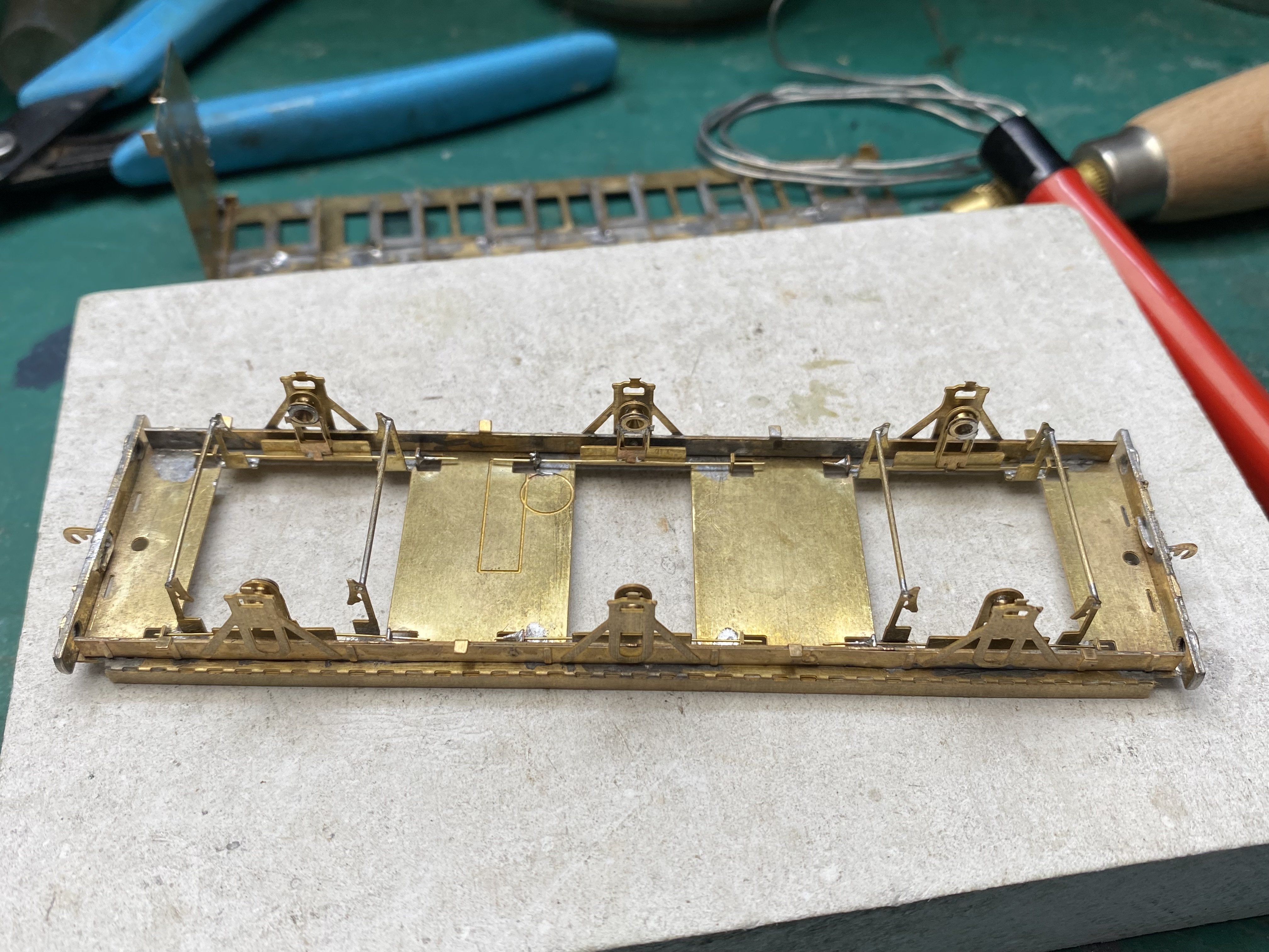
There are guides for the bearing carriers behind each W iron, just visible in this pic. The BCDR practice of outside W irons possibly made this extra layer necessary. The irons are too far apart to retain a standard OO gauge pinpoint axle

-
Verging on the impossible
-

Clogherhead - A GNR(I) Seaside Terminus
Tullygrainey replied to Patrick Davey's topic in Irish Model Layouts
Looks pretty good to me. -
Mystery solved. You were absolutely right David. Six bits of strapping for the bottom of the W irons. Should've been soldered on before any folding up of the chassis and impossibly fiddly to attach now. The first one I attempted pinged off into a parallel universe somewhere and will not return. The rest have now been labelled 'not required on journey'.
-
Thanks David. I think you're right in saying it's a set of 6. I haven't been able to see anything corresponding to them in the photos I have or in DC's lovely drawings. The one side-on pic of this particular vehicle (in Coakham: Irish Broad Gauge Carriages, pg 81) is murky in the solebar area. They may end up residing in my 'spares' drawer
-
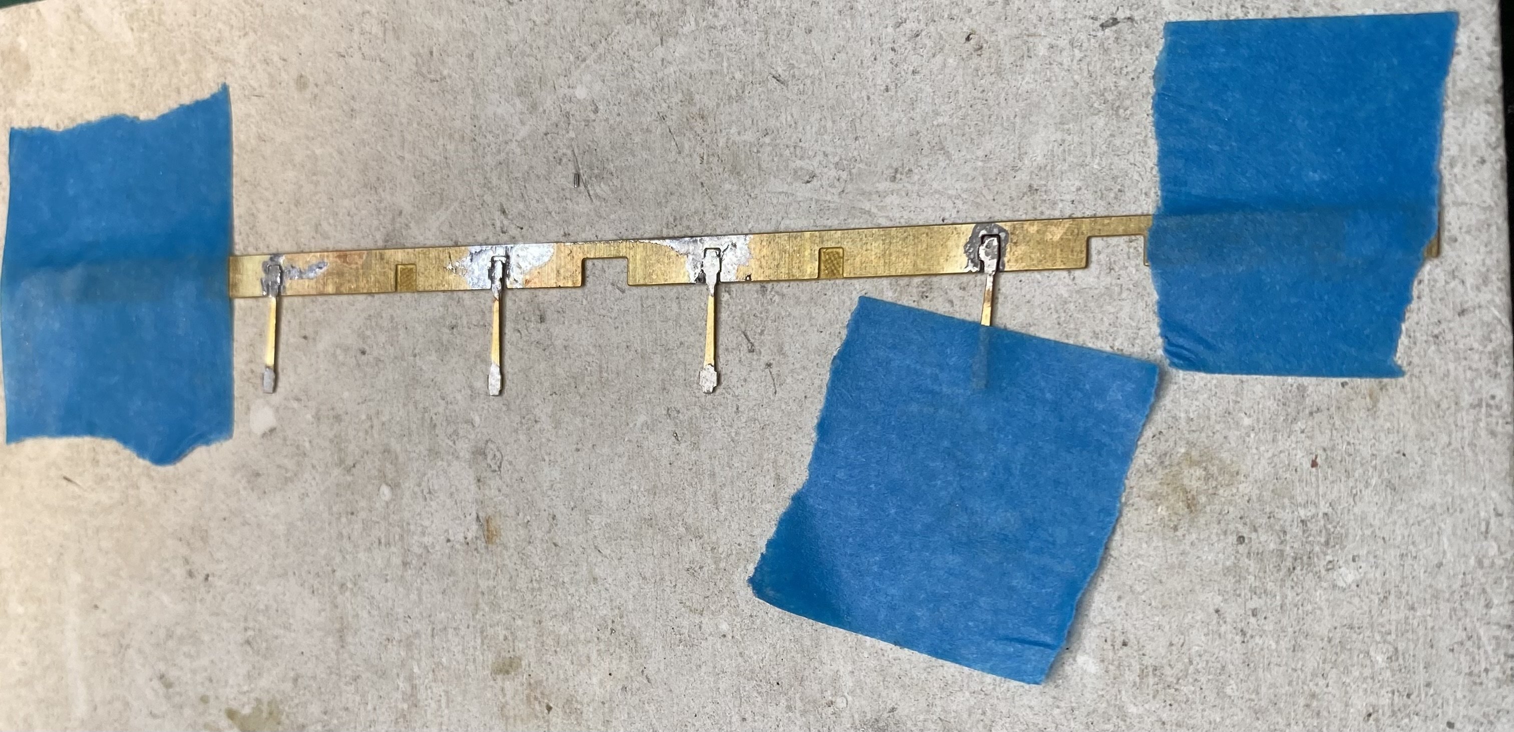
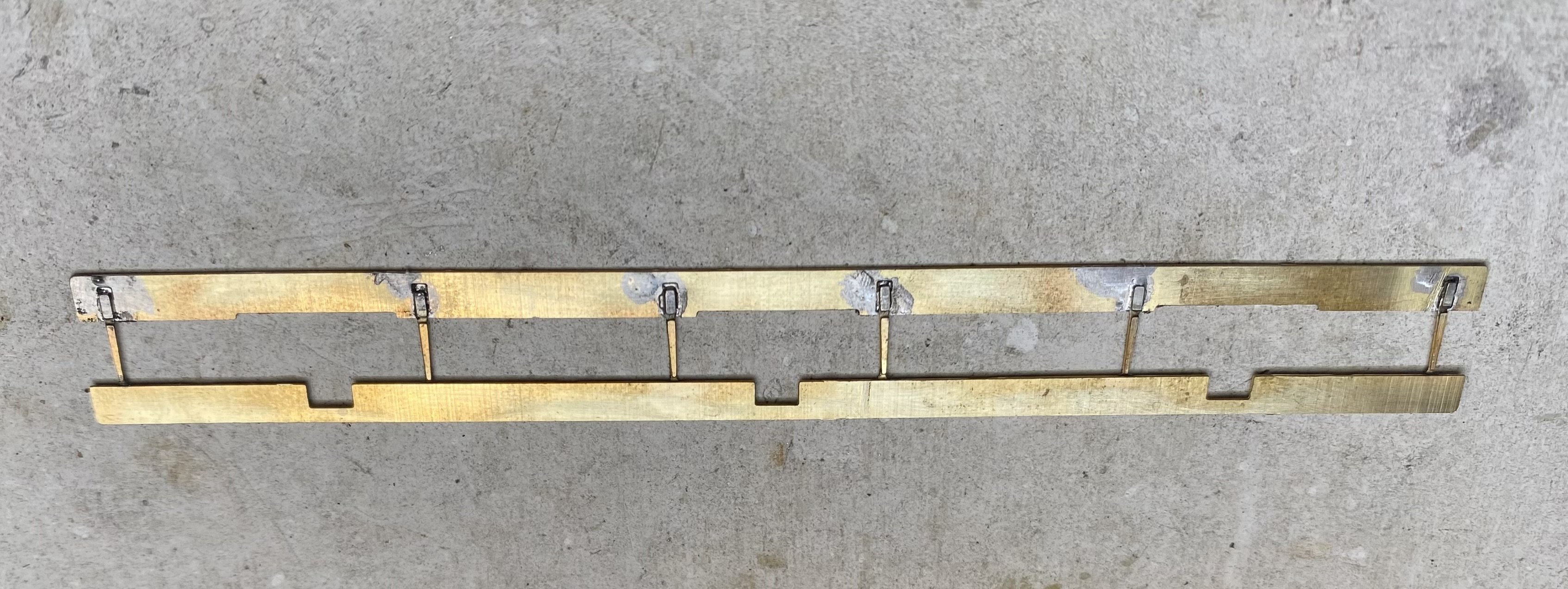
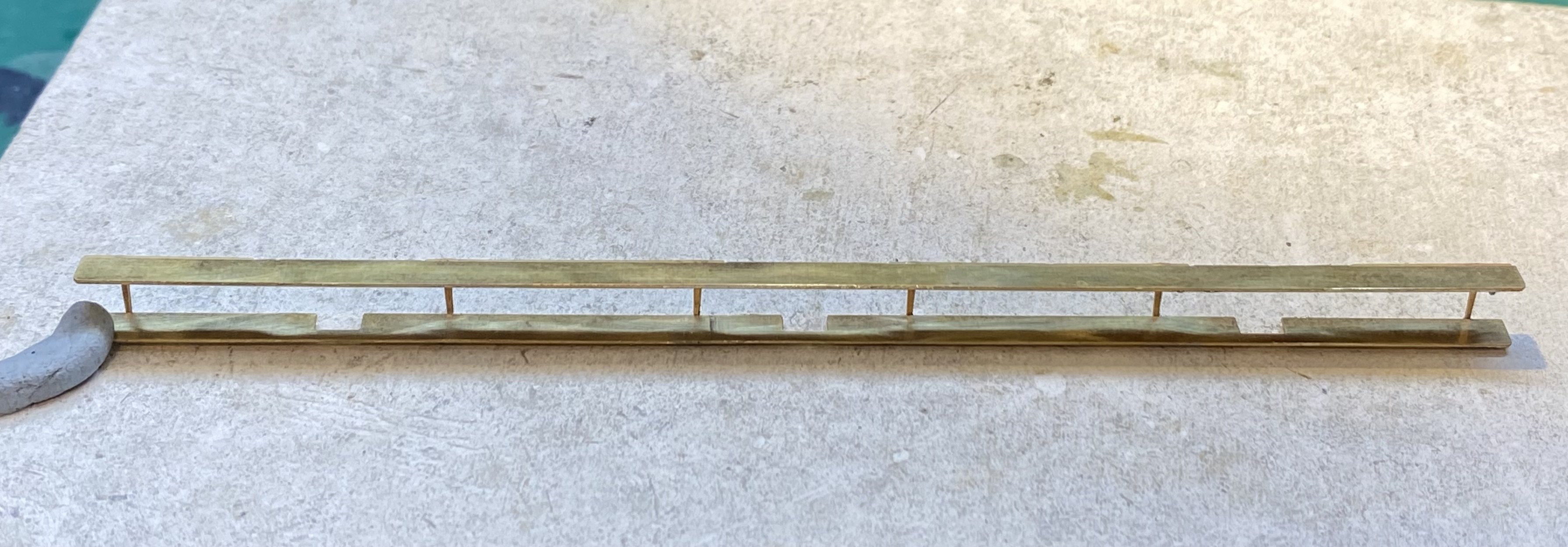
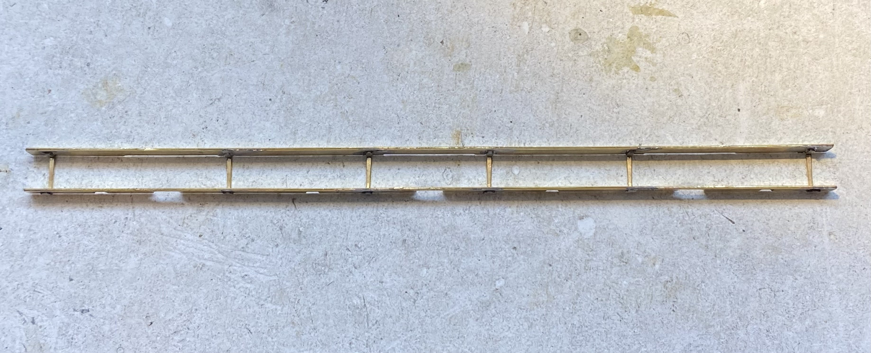
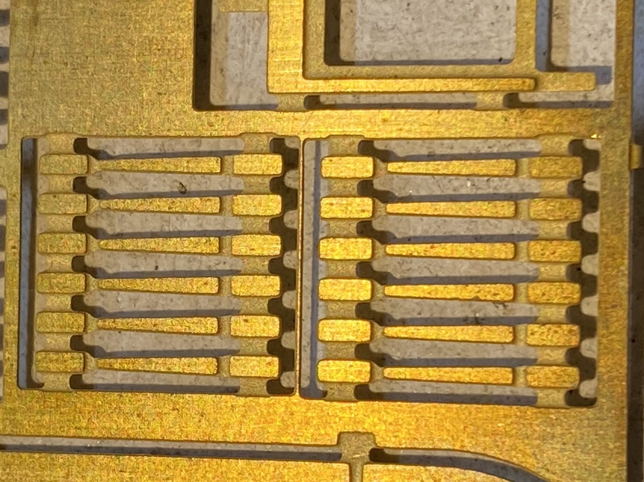
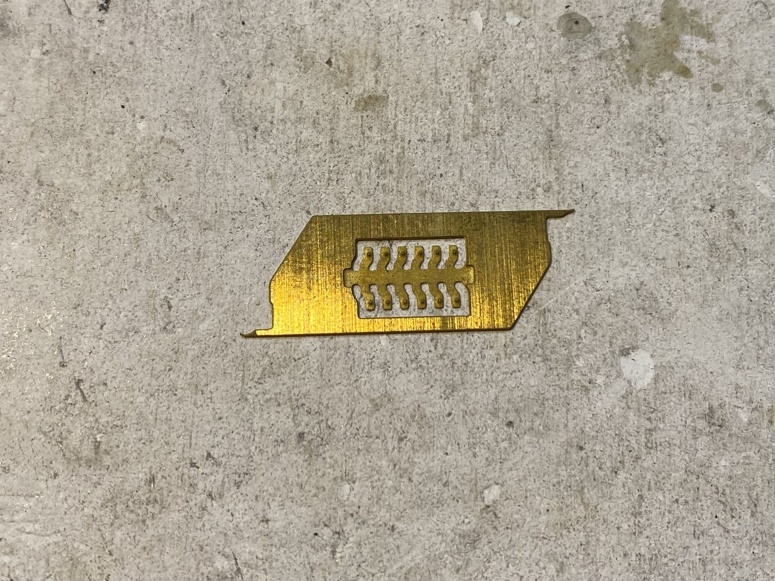
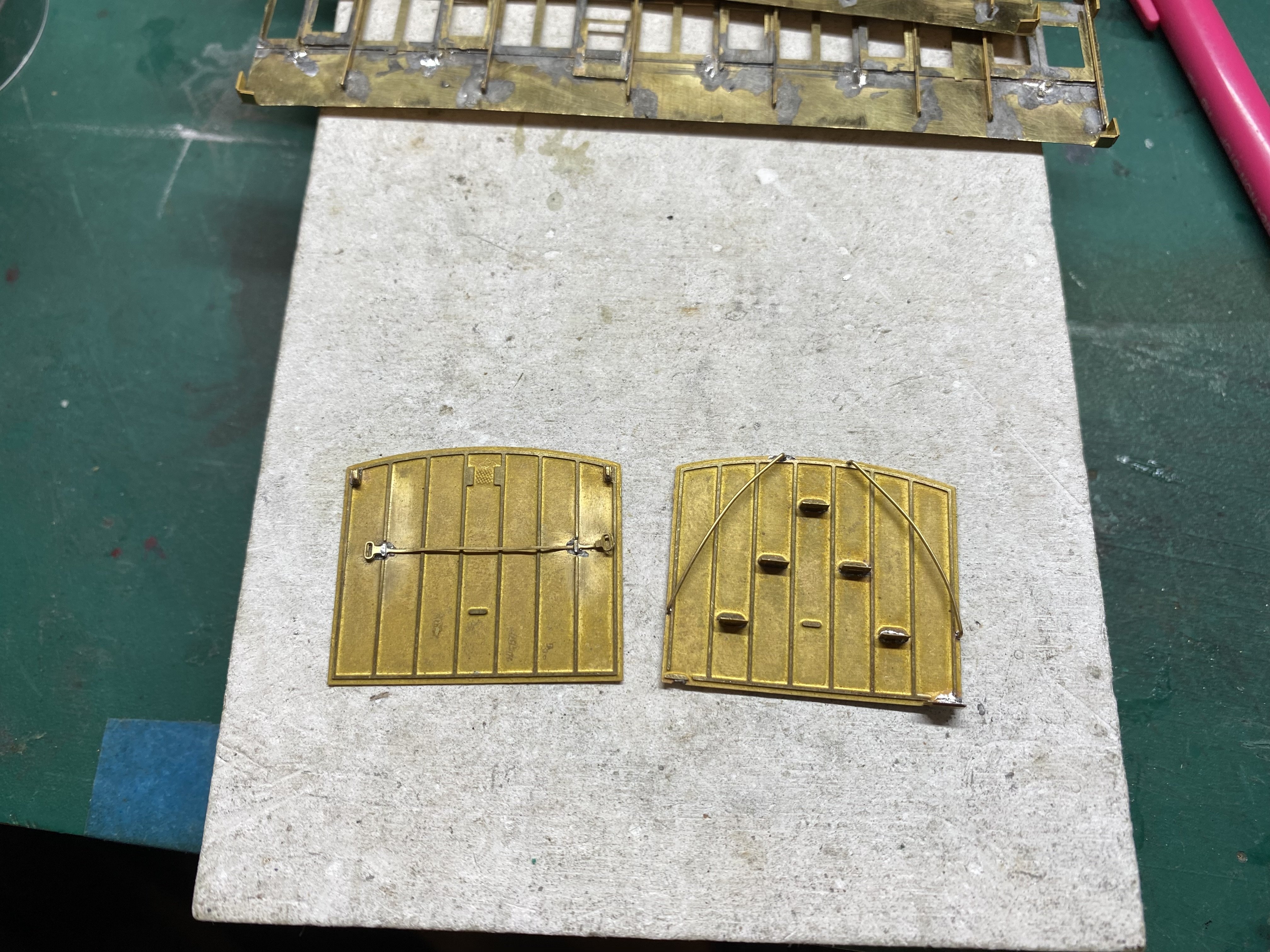
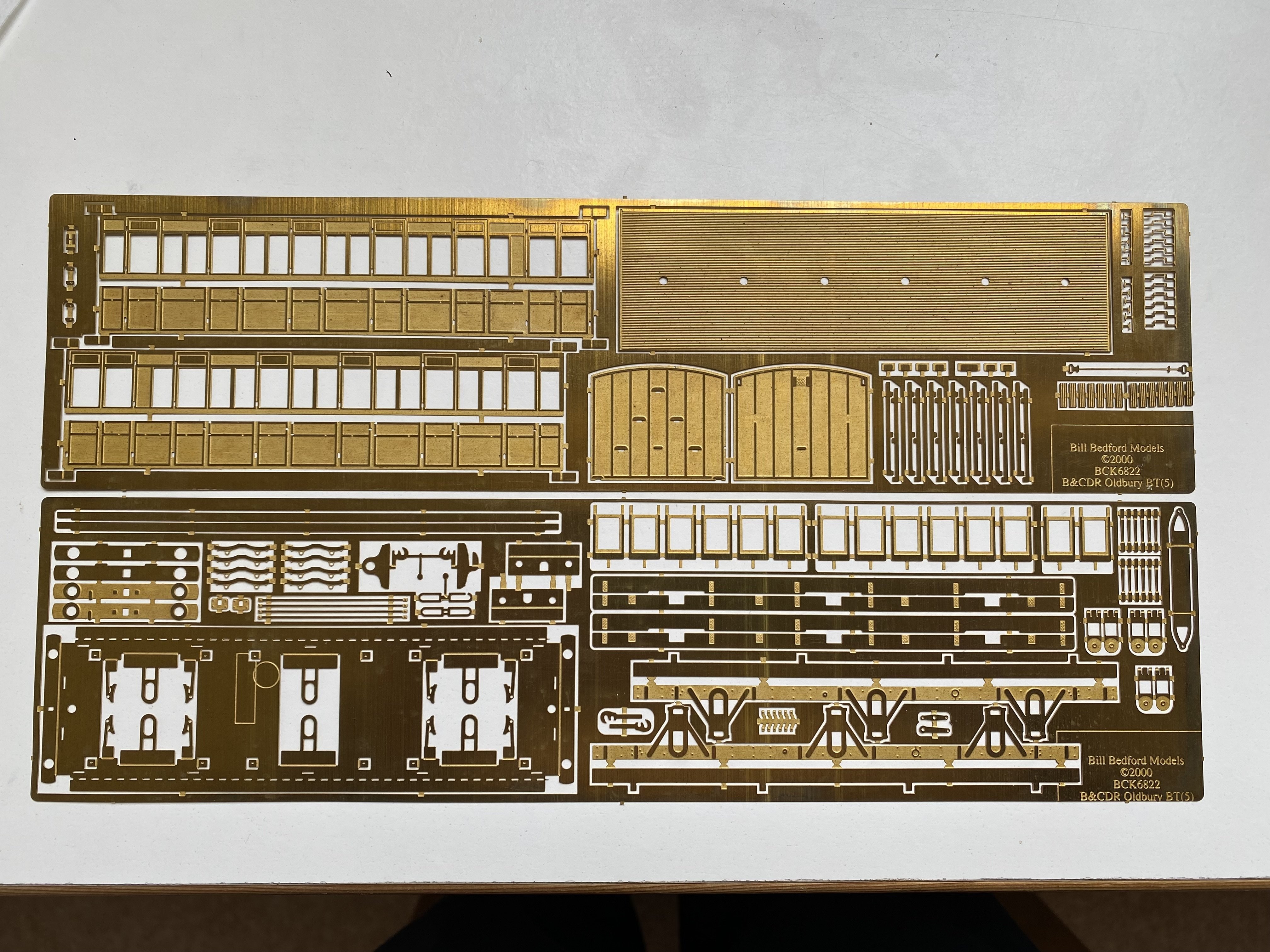
More BCDR coachwork. The Oldbury Brake 3rd has two full-length steps on each side. After some head-scratching, a period of confusion about which step was which and then a fair bit of faffing around, I managed to get them assembled. I’m recording the process as much for my own benefit (I’ve got another one to do) as for anyone else who might be tackling one of these for the first time. Each assembly has 6 struts to hold top and bottom steps parallel to one another. Each strut has 2 half etched lines for folding and there are half-etched pads on the undersides of the steps into which the struts are soldered. I think it’s easiest to make up the step assemblies as separate units before attaching them to the chassis and also to solder them while still flat, before bending the struts, so… Solder struts to the underside of the bottom step, half-etched line downwards… Turn the whole thing over and solder the other ends to the underside of the top step, half-etched line upwards… Fold the bottom step up through 90 degrees… Then fold the top step down through 90 degrees… et voila! The whole caboodle attaches to the chassis by soldering the top step to 4 little tabs folded out from the sole bar. There are four half-etched pads on the underside of the step to help locate it correctly. However, on my set of etches, assuming I’ve understood the build process correctly, these half-etched pads are on the bottom step rather than the top, which would put the steps in the wrong place. This was what confused me in the first instance. It doesn’t really matter - they’re not essential and no kit builder was harmed in the process but this bit of the build really challenged my capacity to visualise in three dimensions. I haven't soldered the steps to the chassis yet because I still need to source appropriate axle boxes from somewhere. Stepping out, but cautiously Alan PS Does anyone know what this is?
-
Clogherhead - A GNR(I) Seaside Terminus
Tullygrainey replied to Patrick Davey's topic in Irish Model Layouts
DAS ist gut! -
Clogherhead - A GNR(I) Seaside Terminus
Tullygrainey replied to Patrick Davey's topic in Irish Model Layouts
Looking good Patrick. Nice photo - two sides of the one quoin. (I'll get my coat) -
Thanks for this JB. Very useful. I like brownish and dark browny-red. It will help disguise the explosion in the solder factory which the interior currently resembles. I've partitioned off the guard's compartment. Do you know how the rest of the interior was partitioned? Did each door give access to only one compartment or was it a more open arrangement?
-
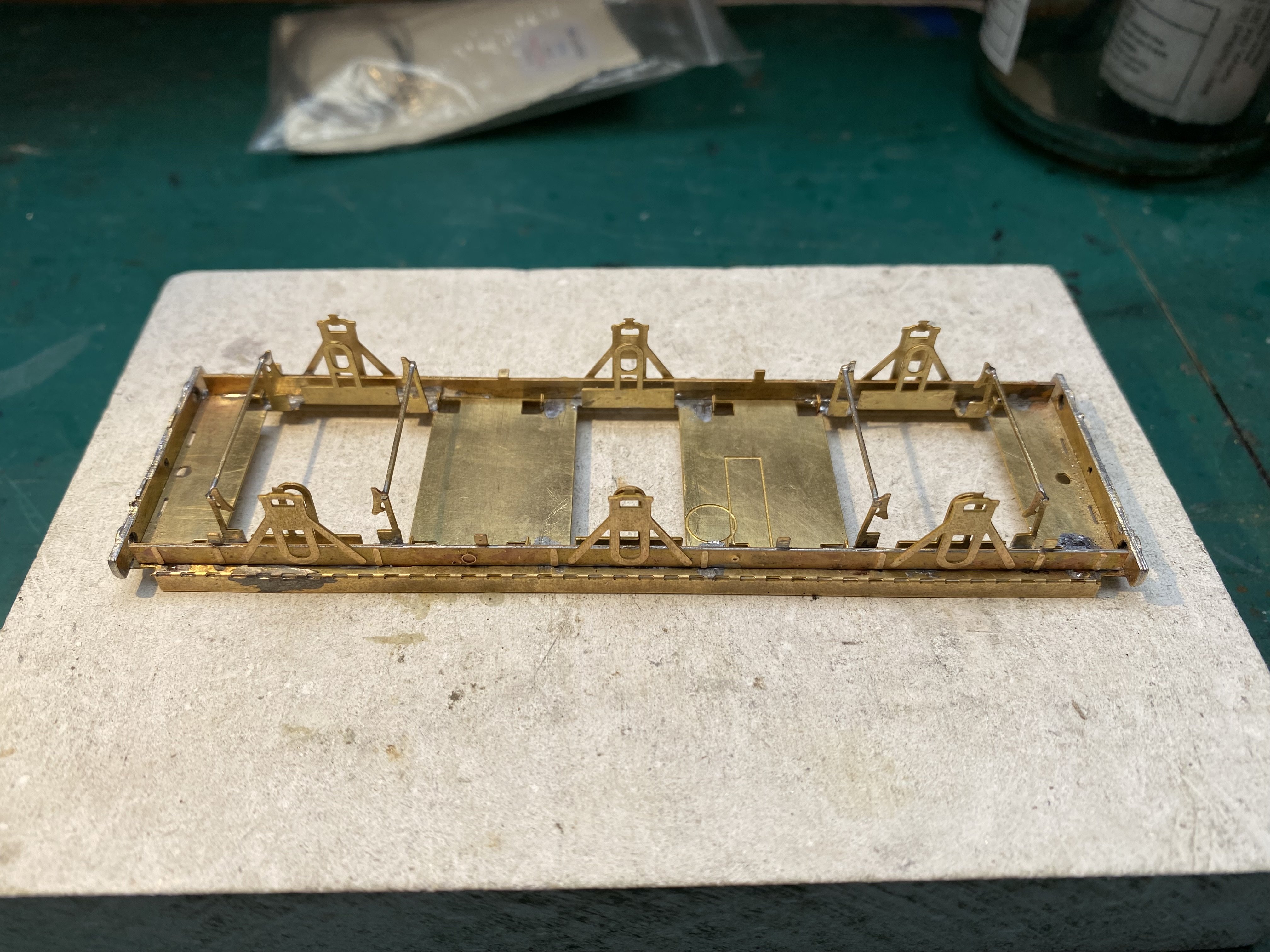
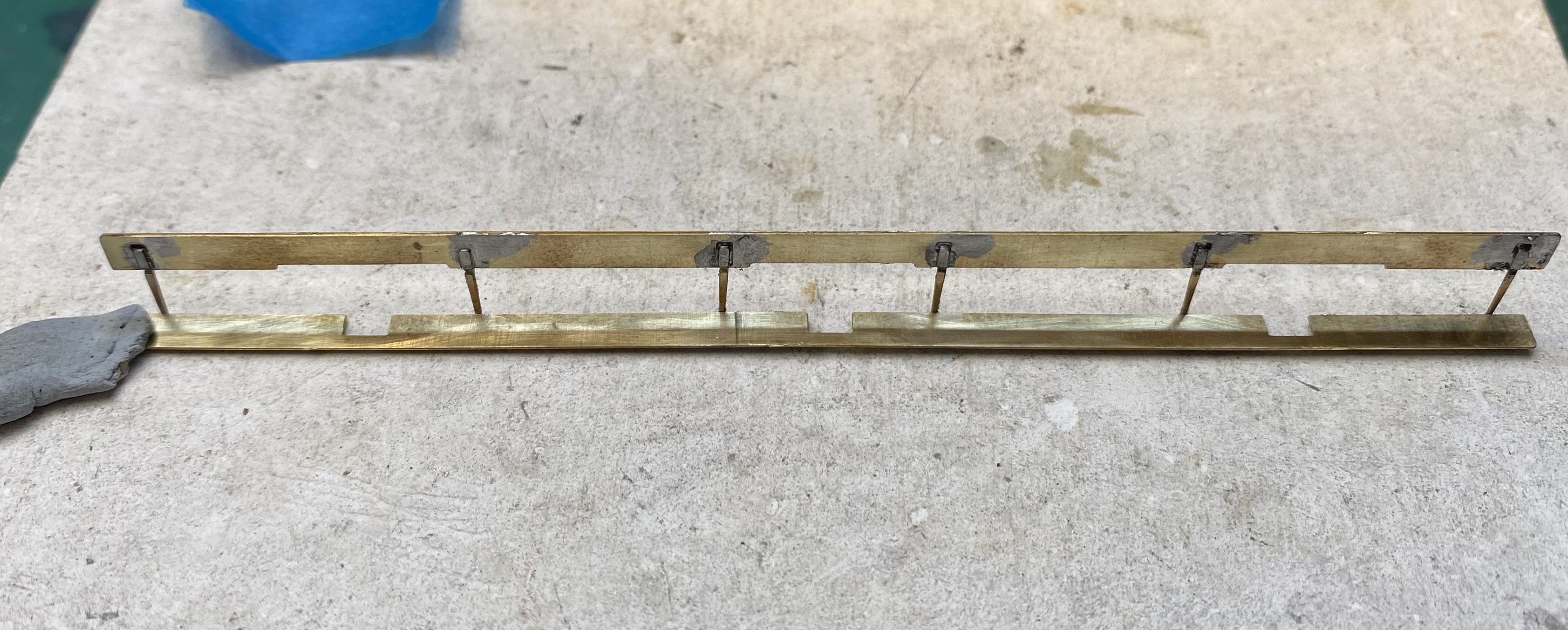
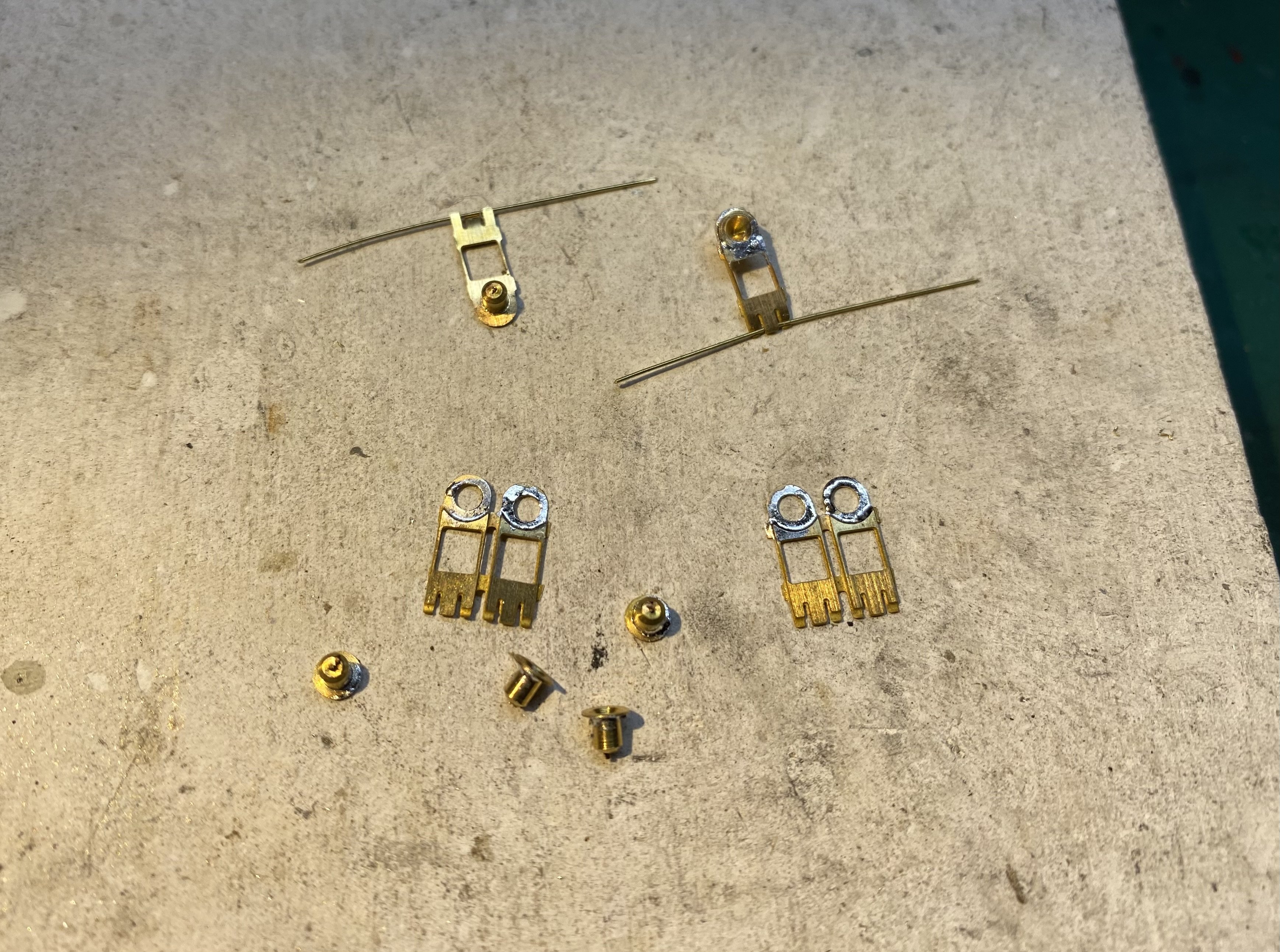
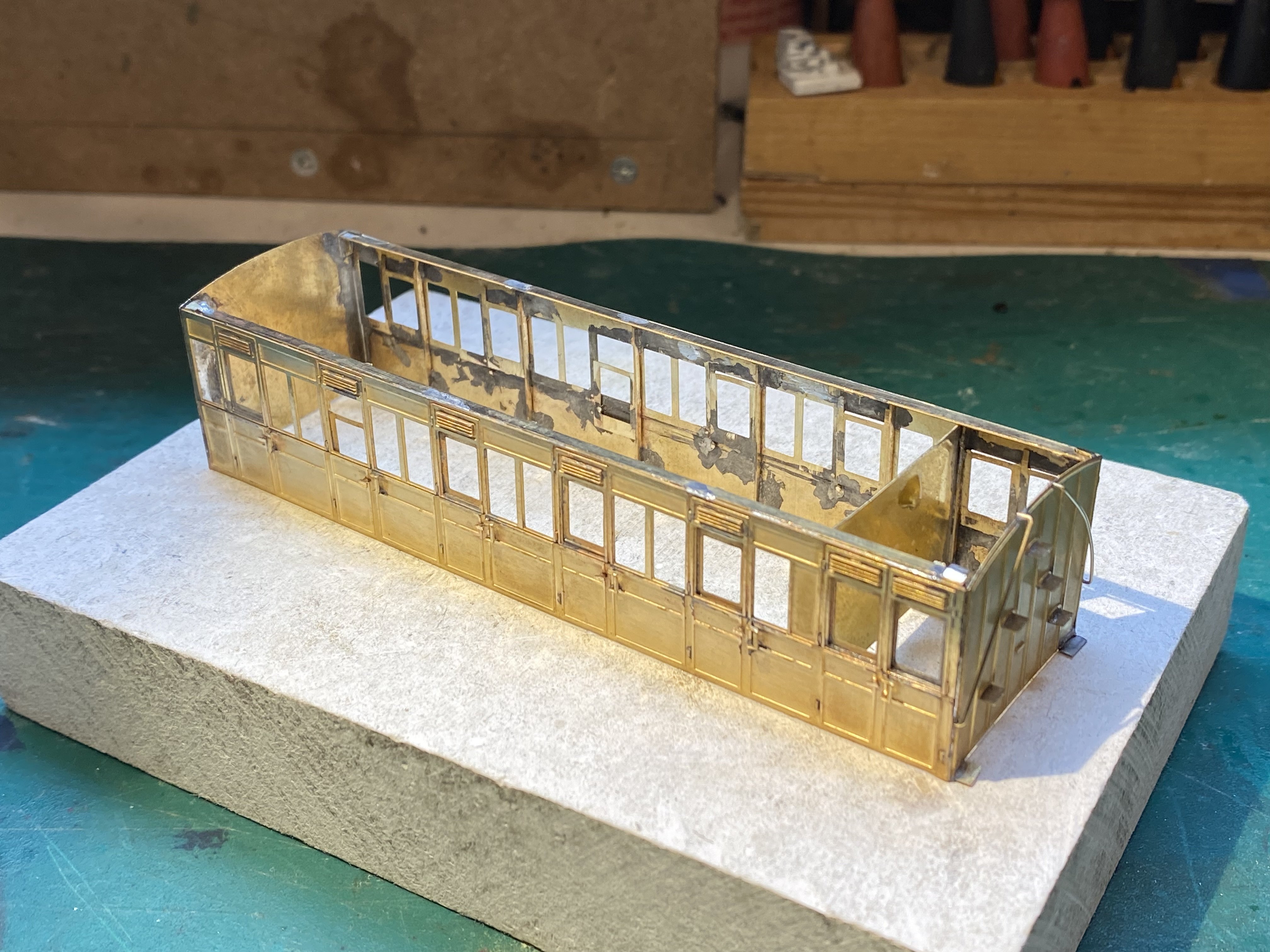
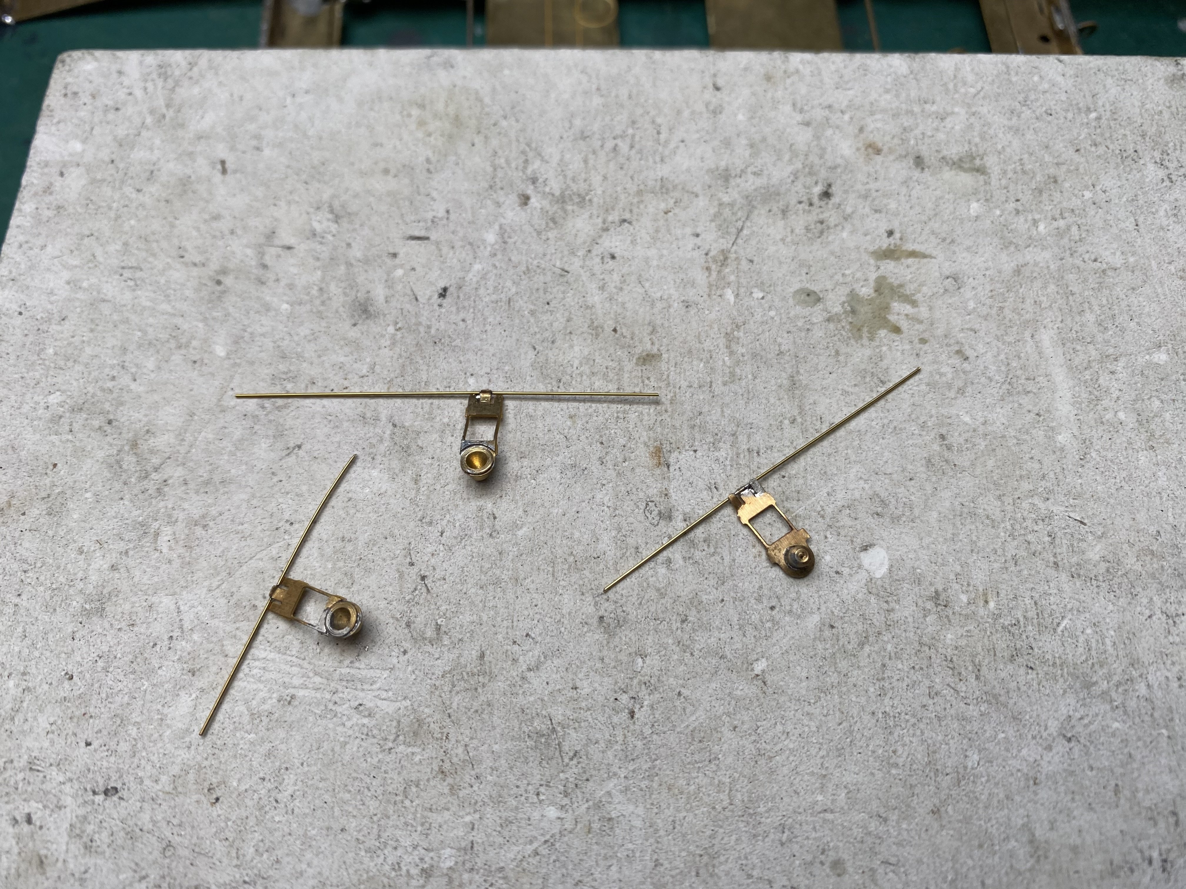
More BCDR Brake Third. Boy, this is tricky stuff! The chassis is designed to be sprung with an arrangement of the wheel bearings similar to one I first came across on etched wagon chassis from Brassmasters. Pinpoint bearings are soldered into bearing carriers (which had to be reamed out first) and then a length of springy wire is threaded between 3 little fingers at the other end of each carrier and soldered in place. I'm not sure what sort of wire is intended for this but I've used 0.33mm brass because that's what I had. It seems to work ok. The carrier etches are really flimsy and distort very easily. For each wheel, the springy wire is fitted at each end into holes in small folded up tabs on the chassis so that the bearing carrier can move up and down in its guide. Soldering each wire at one end keeps it in place while still allowing it to flex. Trying to describe this in words makes it sound more complicated than it is but it's still a fiddle to do. The superstructure is also taking shape. More fiddly stuff and solder everywhere but I've managed to keep most of it on the inside where, hopefully, it won't be seen. I can tell you in advance that this coach won't be having any internal lighting! Soldering sides to ends was difficult. There are fold up tabs at the corners of the sides but it's debatable whether they're a help or a hindrance. I ended up cutting some of them off. I have no idea how the interior of this one is divided. Anyone? Alan
- 613 replies
-
- 11
-

-

-
That's a great idea to extend from the other end of the fiddle yard and link the activities of each layout. Looking good Ken. Alan
-
Erne MRC annual Exhibition and fair - 16th September 2023.
Tullygrainey replied to steventrain's topic in What's On?
Enjoyed the show. Many thanks for a great day out. Alan -
To add to Galteemore's list: Hobby Holidays https://www.hobbyholidays.co.uk/ A terrific selection of brass sheet, section, tubing and rod. Also tools and drill bits and, in my experience, a really prompt service. Recommended.
-
No need for apologies Metrovic. To my mind, one of the fundamental purposes of this forum is for us to learn from one another. I’ve certainly benefited from the collective expertise here. It depends a lot on what you want to do but here are some of the things I’ve relied on when working in plastic, card and metal, modifying ready-to-run stuff, building kits and scratch building. For marking and cutting: Stanley Knife Swann Morton scalpel handle and no.11 blades Steel ruler(s) Razor saw Centre punch/scriber For making holes: Selection of twist drills in sizes 0.5mm, 0.7mm, 1mm, 1.5mm with some pin vices to hold them Set of 6 cutting broaches, 0.6mm to 2.0mm Set of 6 cutting broaches, 1.2 to 3.0mm Cutting broach 4.0mm All of these for making holes and progressively enlarging them. The broaches make sure the holes stay round and where you want them. For shaping and fettling: Small pliers - needle nose and flat jaw Set of needle files - various profiles Fine emery paper For holding and assembling things: Small bench vice (good ones are hard to come by in my experience), preferably with bench clamp and adjustable head. Selection of small clamps (including hair clips and clothes pegs) Selection of good quality tweezers Set of small screwdrivers For soldering: Antex 25W soldering iron and stand 145 degree solder Slater’s Phosphoric acid flux Fibreglass pencil For building etched kits and especially for scratch-building, I’ve also relied heavily the following: Chassis jig (I use a Poppy Woodtech one) GW Models wheel-quartering jig Vertical bench drill (I have a Proxxon) Antex temperature controlled soldering iron Piercing saw and a selection of blades I found that I built up this stock of tools very gradually, buying things as it became clear that I needed them for the job in hand. My bench drill only arrived when I started to scratch-build. It’s good advice to buy the best quality you can afford. Very cheap tools, as almost everyone has probably discovered, are nearly always a waste of money. I treated myself to a few proper Vallorbe Swiss needle files and haven’t regretted it. I'm sure that as soon as I post this, I’ll think of more tools I can’t do without. I’m sure too that others will chip in here with their own lists. I hope so. When all’s said and done, the item I’ve found the most useful is patience. It’s versatile, can be applied to any task and usually improves the outcome. I just wish I could find a reliable supplier. I keep running out. Very best wishes for your modelling and if in doubt, post a question on this forum. It’s certain that someone will have the answer. Cheers Alan
-
That is a very clever arrangement!
-
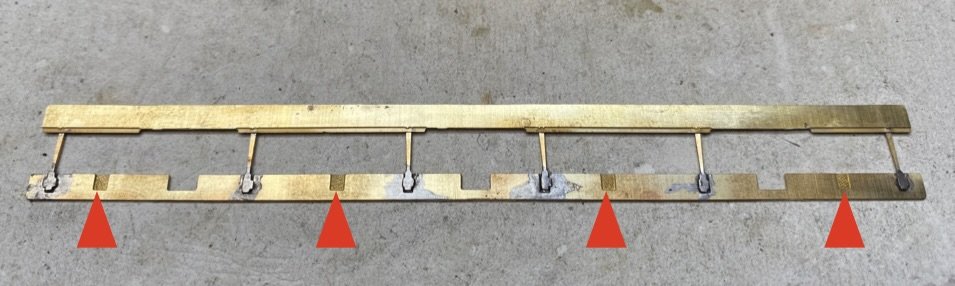
Thanks for this David. All grist to the mill. I'm assuming the 2 longitudinal rods running through the 3 separate bits are there to align them, whilst allowing for different wheelbases? As an aside, leafing through your workbench entries I'm reminded just how much valuable information and insight is tucked away in this forum's back-pages. Finding what you need is the tricky bit! Cheers, Alan
-
Thanks everyone. The etches are excellent but there are still a few mystery bits on there! The etches I'm using resided in Patrick Davey's future projects drawer for some time before migrating to mine. They're still available through Mousa Models and may come with some fittings - sprung buffers are mentioned - but not wheels. There's a choice of three variants, 6 Compartment 3rd, 5 Compartment 3rd and Brake 3rd, all Oldbury. Ah, the wheels David... that's a bridge still to be crossed (not to mention curves negotiated). From the people I've talked to, it's clear there are lots of ways to tackle this, from grinding off the wheel flanges on the centre axle to replacing the centre axle with a length of 2mm tube sliding from side to side on a rod fixed between the bearings. I know there are also some good approaches to this in KMCE's workbench and I need to have another look at those too. The current range of 6-wheelers from Hattons use a clever sliding cradle for the centre axle which seems to work well but might be difficult to build from scratch. I'm still wrestling with door handles
-
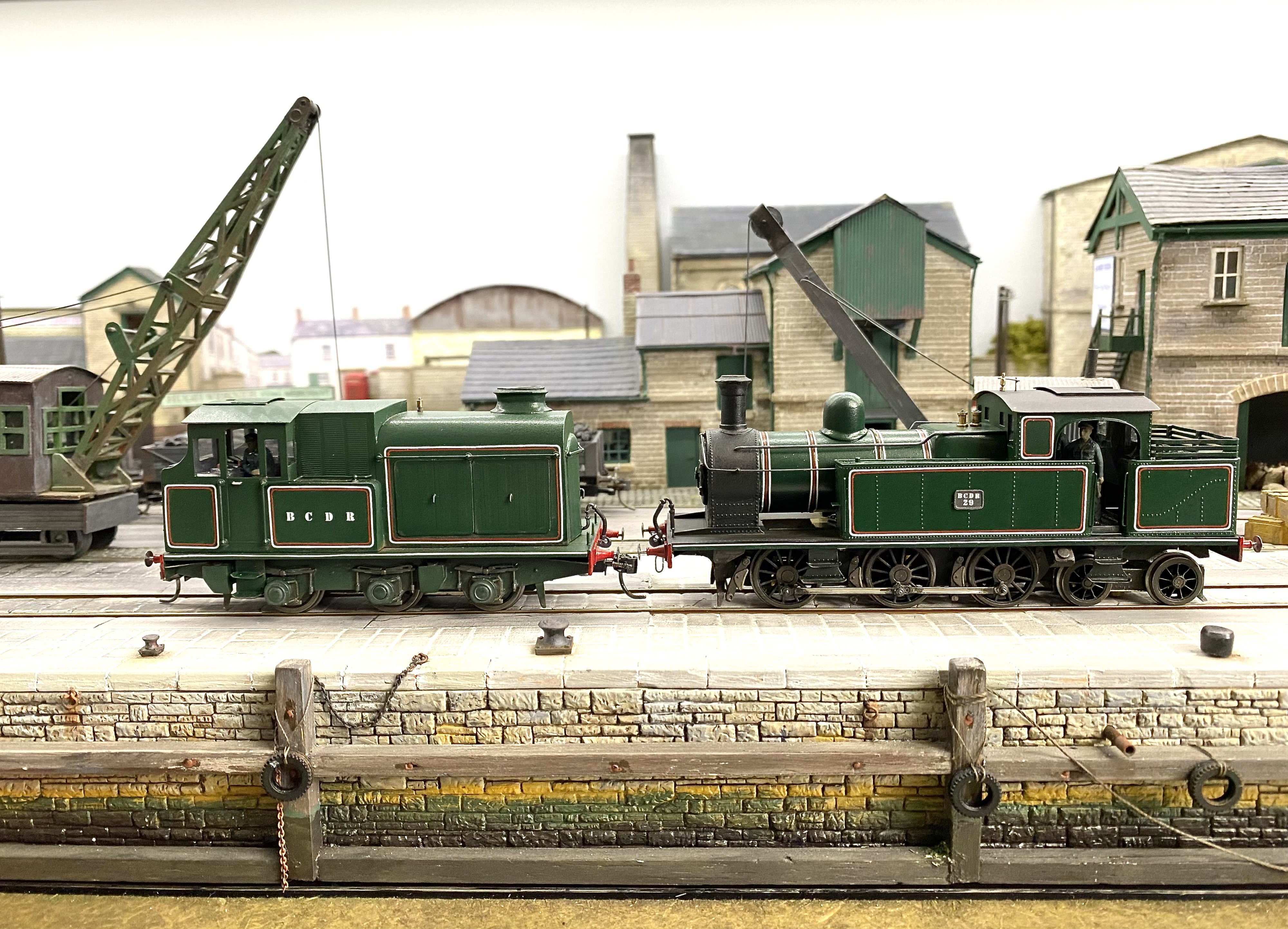
Now that BCDR diesel electric No.2 is up and running, it really needs something more appropriate to haul than a couple of box vans so I'm hoping to have a go at modelling a typical passenger formation from the Ballynahinch branch where No.2 worked for so much of its life. To that end, I've acquired some Bill Bedford etches for BCDR Oldbury 6-wheelers (thank you Patrick) No castings and, more to the point, no instructions so something of a Chinese puzzle on first sight. However, sound advice and some very useful photographs from folk who know about these things (thank you Richard, thank you Kieran, thank you Colm) have pointed me in the right direction. A visit to the Downpatrick open day at the weekend also helped and Desmond Coakham's peerless work is, as always, an invaluable source of information. So, I've made a start on an Oldbury Brake Third.The fitters are confident there will be hardly any bits left over when the job's finished. Knee-deep in door handles Alan
-
Clogherhead - A GNR(I) Seaside Terminus
Tullygrainey replied to Patrick Davey's topic in Irish Model Layouts
Go for it Patrick! Sight AND sound. No point in half-measures. Follow your instincts (and have you given any thought to how a Clogherhead sea breeze smells?) -
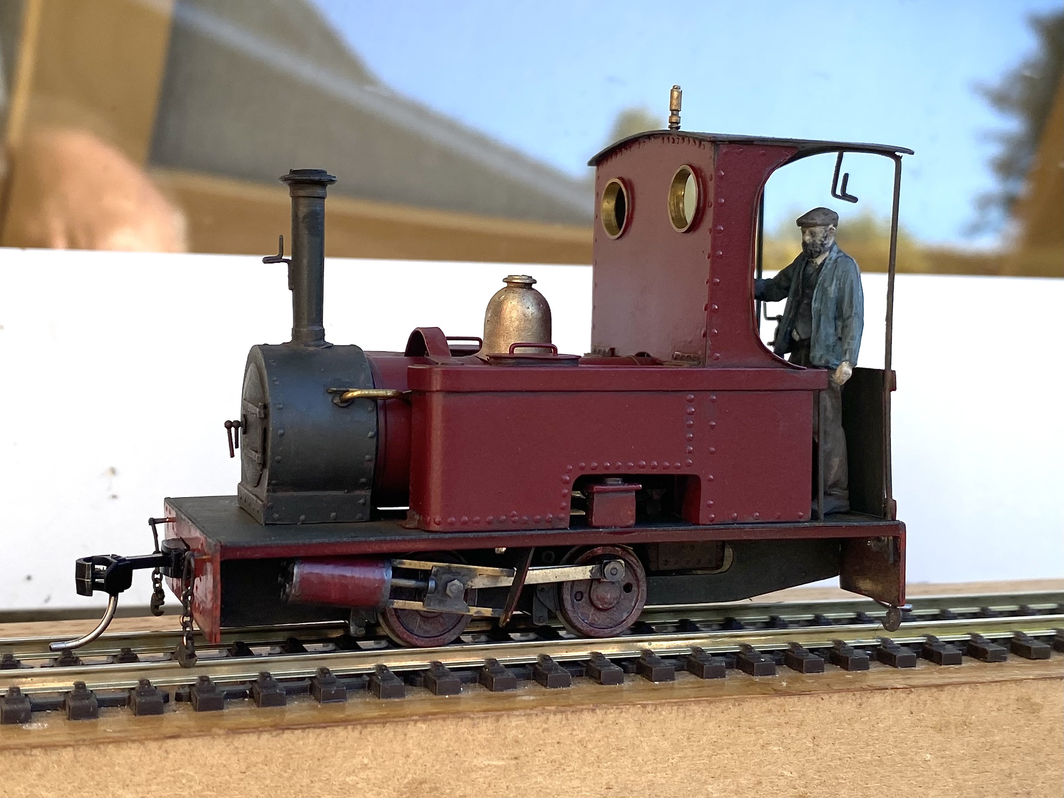
Ah, working now I think Thank you. The little Peckett runs like a sewing machine. I'm well pleased with it
-
Whoops. Sorry JB, not sure what's wrong. It's playing ok for me but that doesn't mean anything. It's an mp4 file
-
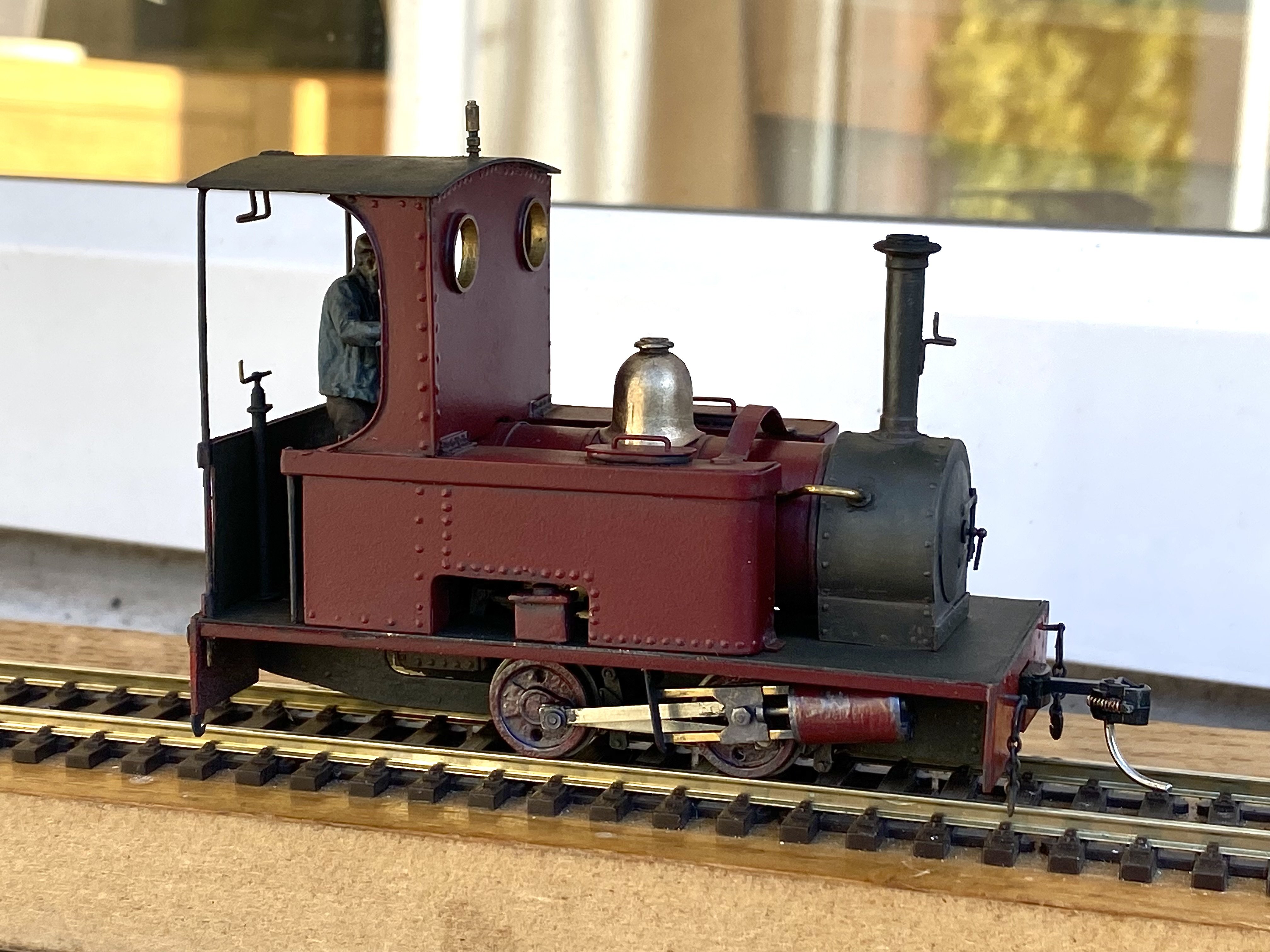
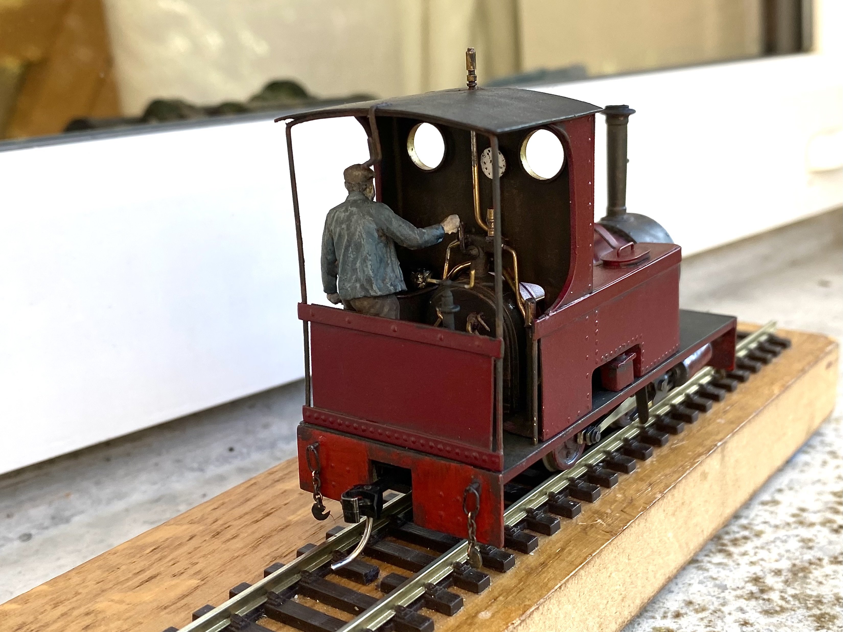
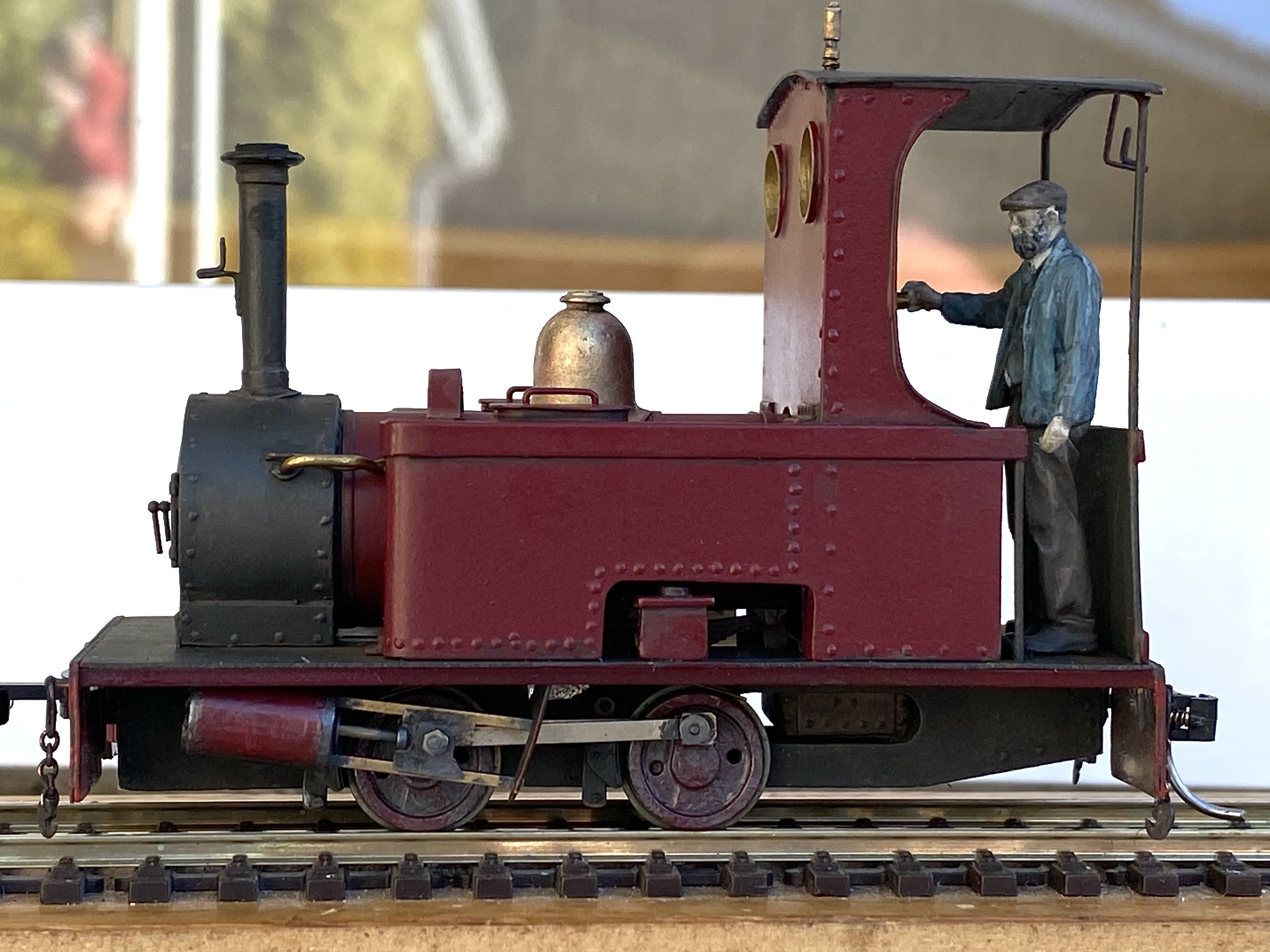
Some activity at the narrow gauge stone yard, somewhere in County Down/Antrim. Locomotives at work, including a recently arrived Peckett, already earning its keep bringing stone from the quarries and shuttling empties back. The Stone Yard.mp4
- 113 replies
-
- 17
-
-

-
Peckett has emerged from the paint shop at long last. There were a few hiccups with the job (of course there were) not to mention a colour change along the way but I think it's about finished. It's had a little weathering to take the shine off it. It also has a cheap chip from Hatton's and some lead in the tanks so it shuffles along in a satisfying narrow-gaugey sort of way. It will make an appearance at the O:16.5 narrow gauge stone yard in due course. Meet Pete, the Peckett pilot.
- 613 replies
-
- 17
-
-
-
Beautiful paint finish on the loco Ken. Looks really well and a great lineup of loco plus coaches
-
That weathering is spot-on. Subtle and totally believable. Lovely work.