Northroader
-
Posts
375 -
Joined
-
Last visited
-
Days Won
2
Content Type
Profiles
Forums
Events
Gallery
Blogs
Everything posted by Northroader
-
Elizabeth line to Stratford, and pick up a St, Pancras to Dover there. (Route via Ashford) Taxi from Dover Priory is best way to finish. then again, maybe not, there’s a big gap between Stratford Underground and Stratford International (taxi?) so it’s fight your way through St.P to the Southeastern station.
-
In Cardiff, we had seagulls nesting on Cathays wagon shop roof, and they were a damn nuisance in the summer, walk up the yard and you would get divebombed. Now over at Canton, you’d get Terns nesting on top of the Black Shed, (the carriage shed), they weren’t such a nuisance. i haven’t been that way for a while, but all the third rail substations on the Southern used to have a big plastic eagle owl perched up on top of the high voltage breakers.
-
Really very sorry to hear this. He came across on here as a very genuine person, and i drew a lot of inspiration from his modelling. Condolences to his family.
-
Thanks, David, it is fun, definitely. When I posted that I was a bit down with problems getting sixcoupled locos through Peco setrak points and getting buffer locking as well, and of course I would, wouldn’t I? Quarts, pint pots, and so on. Today I’m rejigging and feeling far more positive.
-
“With hand built track and hand built locos there is significant potential for error”.. you ain’t kidding, I’m very much bogged down at present, and really admiring what you’ve pulled off.
-
Having seen what you can produce over in the RMweb Microlayouts section, I’m looking forward to seeing how your fireside thoughts develop.
-
LNERW1 Starts Arguments-Episode II: The Thomas Menace
Northroader replied to LNERW1's topic in General Chat
There’s a similar line which must have drawn its inspiration from Thomas, and that’s “Ivor the engine”, just one engine set with in Wales with the folks round him. I would think that this could be adapted to an Irish setting quite easily. Theres a simple layout constructed on this theme described in this issue of the “Dispatch”, just page down until you reach “Ivor the Engine” https://micromodelrailwaydispatch.com/wp-content/uploads/2022/09/Issue-6_final1.pdf -
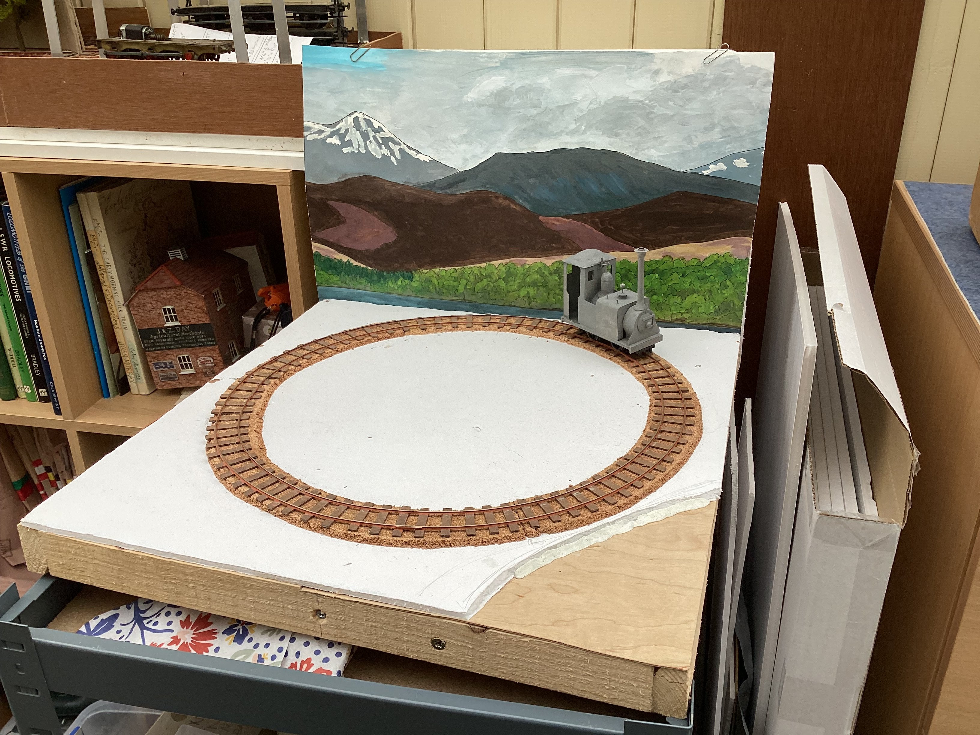
Here’s what it looks like at present, the whole lot has shrunk to fit a circuit on an 18” square board, based on the premise “what would the Highland Railway look like if it was narrow gauge?” But you could apply the same principle to most lines.

-
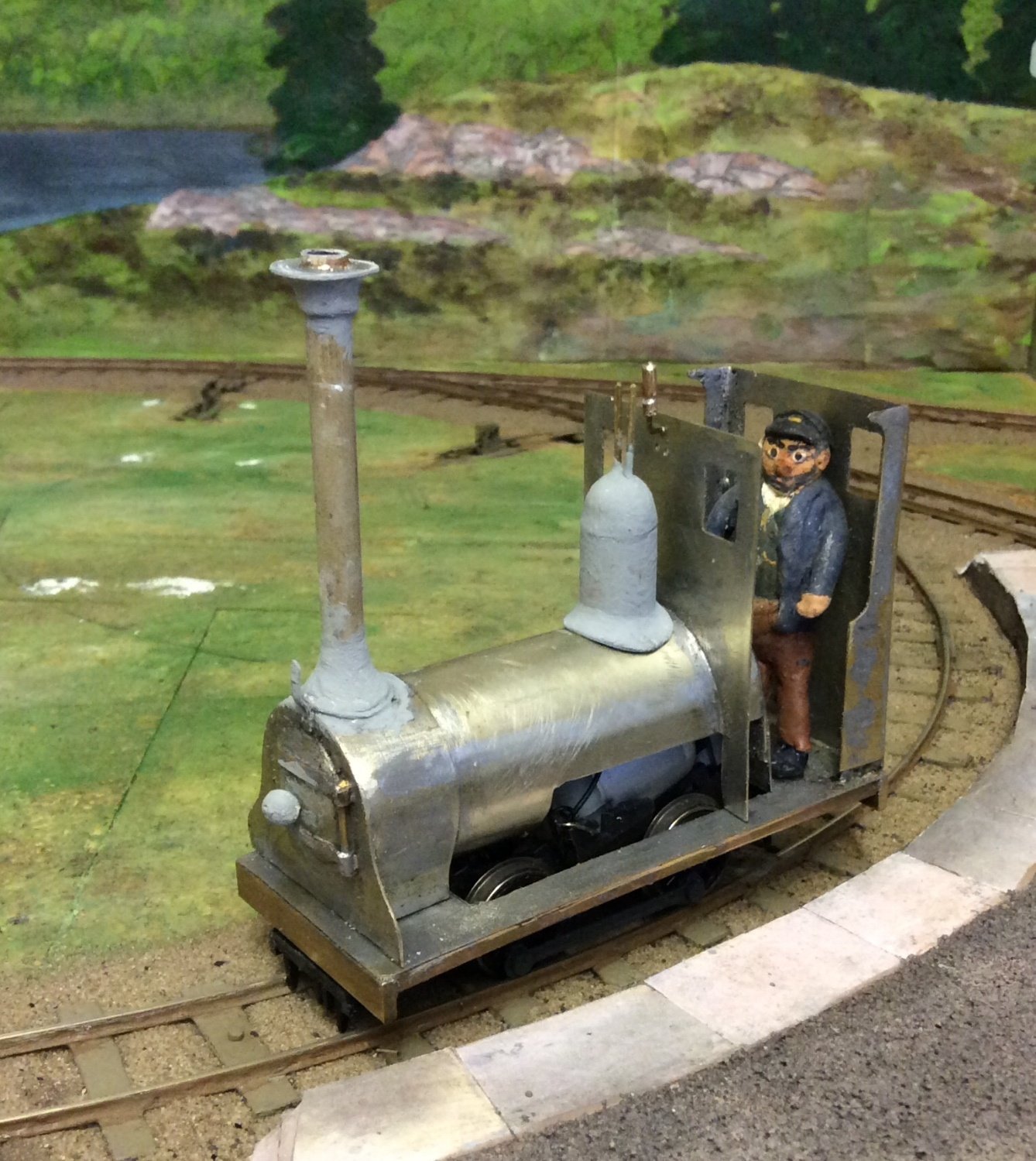
Would you be tempted by a caricature job, narrower gauge and larger scale, mine’s 1:32 scale, 20” gauge with 16.5mm track, or 1:34 scale, 9mm/foot, 22” gauge, which has some commercial figures available?
-
You strap them on your upper arm, so that everyone knows who’s doing a particular task, and remind you of your responsibilities. The pilot man comes into use for emergency single line working, any train passing through the affected stretch has to have him with the train, rather like a single line token with arms and legs. The lookout man goes with everyone working on the track where trains are operating, he has to be placed where he can see trains coming in time to give adequate warning for the guys to get clear. PICOP is where you have possession of a stretch of track for engineering work, but you can still get trains wanting to pass through, such as a ballast train, say, and he has to give permission for the train to pass through that stretch, and make sure everybody is clear, also sign for the start and finish of possession. Engineering Supervisor is similar without the possession, mainly worrying about stuff like lookouts. TSC is something stitched on since I retired.
-
I think with a model the wheels are hardly ever individually sprung like a full size job. If any carrying wheels form a hard point, they’re going to rob the driving wheels of adhesion. Therefore the lead scattered round inside the loco should be arranged so that the centre of gravity is over the drivers, and the bogie, in this case, is allowed to flop about without getting in the way, with enough weight or central springing to ensure it stays on the track. The Swilly engines look in photos to be a bit careworn, so does it really need an out of shops appearance? Just touch up any bare metal that’s appeared.
-
I was thinking just try increasing the width of your slot, so’s the bogie can traverse sideways a bit more?
-
Over on RMweb they’ve been going on about the IKEA “Mosslanda” display shelf as suitable for a short narrow run which should fit this purpose.
-
Highly unusual composition, and works very well. The low relief coach sides are a different way of doing things, certainly.
-
Having it all formed up into a train, that’s a lovely piece of modelling.
-
Really involved constructional work, I’d be scared how sturdy it would prove to be if I was doing it, but going through your materials it sounds strong enough. I found there’s a great temptation picking up those canopies for your fingers to curl over the edges, where the daggerboards are, so don't be like Bob. The appearance of the end result will set off the cameo very well.
-
Clogherhead - A GNR(I) Seaside Terminus
Northroader replied to Patrick Davey's topic in Irish Model Layouts
Ye’ve left no stone unturned with your modelling there. -
Marvellous piece of modelling.
-
You’re right, it’s all the curves in the bodywork. Buried in all the boxes somewhere there’s a few pieces for the NCC one. Will I ever do it? will I ever find it? Yours is an inspirational job.
-
Don’t forget this one is fairly close to you. https://swindon-cricklade-railway.org
-
Who might have built a line to Craggy Island
Northroader replied to Bob49's question in Questions & Answers
If you’re after the West Clare, or most of the other Irish narrow gauge lines, there’s a retired English priest called Roger Farnworth who has done a thoroughgoing research on the line. I marvel at his output and quality of what he does. Just to get you started: https://rogerfarnworth.com/2019/04/08/the-west-clare-railway-part-1-ennis-to-corofin/ -
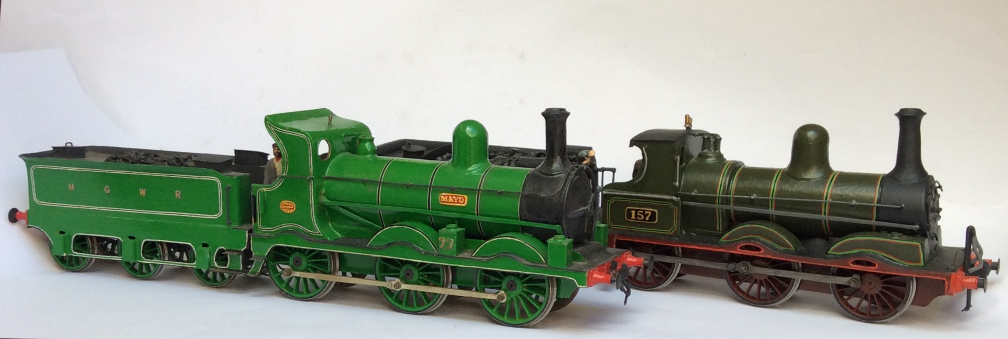
That’s real talent, putting together an etch for a job like that. Hopefully, it’s a real sweet runner, certainly I’ve found doing compensation on the drivers for this size of loco is a waste of time if it’s built true to start with. I’m guessing you’re allowing the lead axle some “float”, the etch shows a hole rather than a slot, and you’ll need some deflection or the lead axle will rob the drivers of adhesive weight. your comments on the size of 7mm are interesting, I’m sure once you’ve picked up the finished loco and felt the bulk of it in your hand a few times, you’ll be very disappointed with the 4mm jobs you have for the “feel” they give. Another one joins the club!
-
Who might have built a line to Craggy Island
Northroader replied to Bob49's question in Questions & Answers
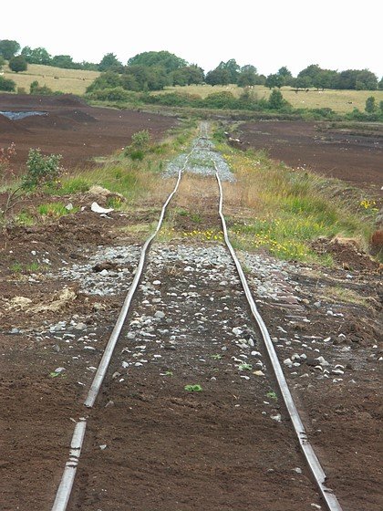
I see it as pretty basic narrow gauge, sort of Bord na Mona without the peat wagons, just a wagonmaster diesel and a converted caravan on overgrown sectional track.