murrayec
-
Posts
2,758 -
Joined
-
Last visited
-
Days Won
70
Content Type
Profiles
Forums
Events
Gallery
Blogs
Community Map
Everything posted by murrayec
-
 Yes, that's them. You may have to shop around as scanning & printing large scale drawings can be expensive! Eoin
 -
Hi Callum, If you bring the drawings you have to a scanning service and get them to scan and print at the scale factor you require. You say you have ''full size drawings'' but obviously these are scaled drawings to fit on a drawing sheet, the scale of the drawing should be indicated in the Title Block of the drawing. Knowing the drawing scale one can then calculates the scale factor you want them printed at, the printing service will have to print the final drawings over several sheets as 1 to 8 ratio will be a large drawing for a loco that size! Hacketts may be able to help, give them a call...... Eoin
- 5 replies
-
- 2
-

-
- 184mm
- 7 1/4 inch gauge
- (and 2 more)
-
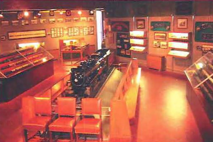
This used to be in the Fry Castle Museum, CIE commissioned it for display at a show in the UK, not built by Fry but ended up in the museum. It used to reside in St Andrews Church (Tourist Office) Suffolk Street, not sure if it is still there! Eoin

-
It is believed by some, that light fingered chaps were at work here- way back at the setting up of the Castle Museum! There is also evidence in the collection that some of the Fry 3 rail models were converted to two rail....... Eoin
-
OBB HOe layout "Connafeld"
murrayec replied to Georgeconna's topic in Continental European Modelling
Practicing your icing skills there George, Christmas is coming Eoin -
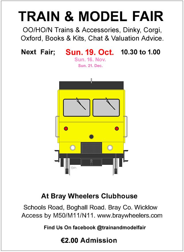
October's Fair Date:-
-
until
-
We were hit yesterday afternoon here in Kilmacanogue, my neighbor's sheds were flattened by a tree fall, if it had gone in another direction it could have been my garage!! Eoin
-
@Flying Snail Cutting paper & cardboard about 10 cutting projects. For Styrene I'd change the blade after 2 cutting projects. The blades come in the barrel body, one replaces the whole thing, last time I bought one was a while back, I think around £26.00
- 26 replies
-
- 2
-
-

-
- lathe work
- machines
- (and 1 more)
-
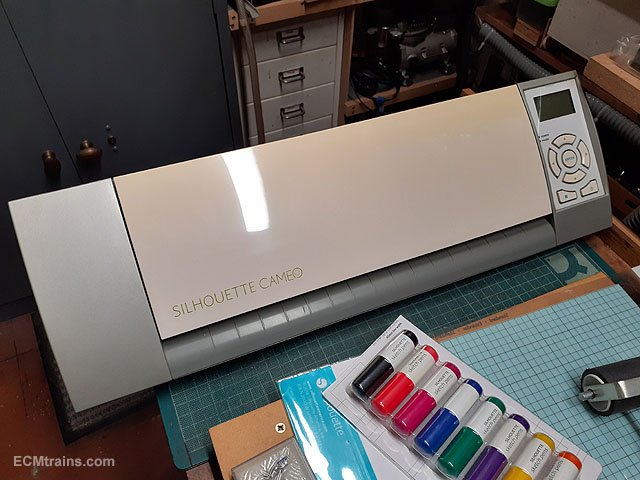
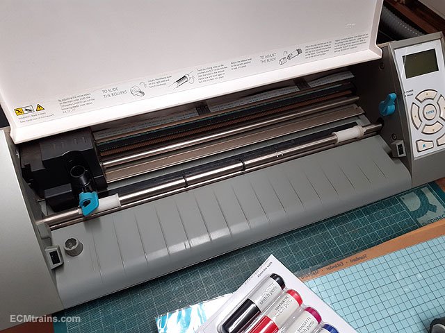
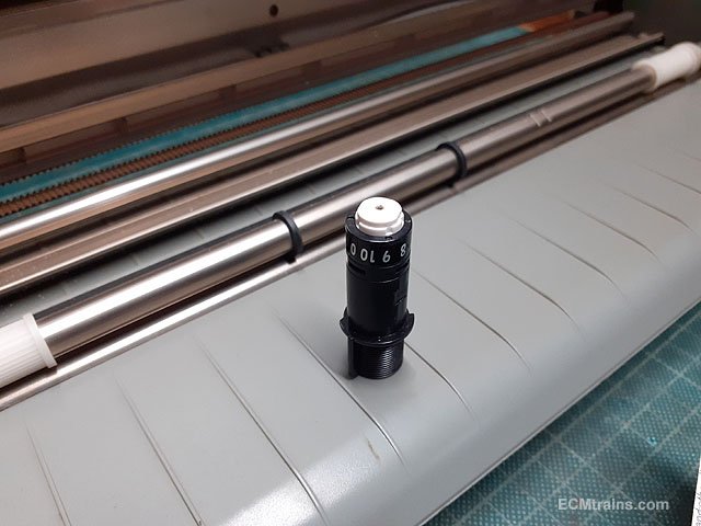
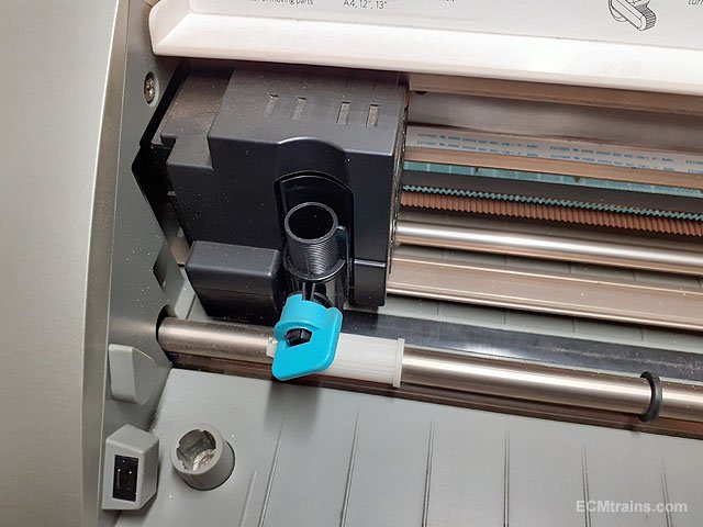
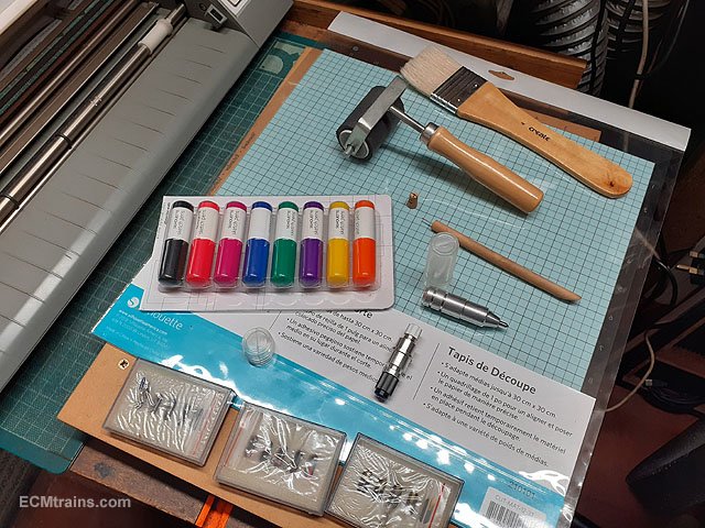
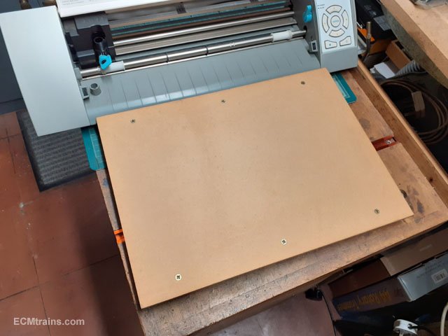
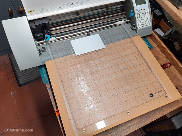
Silhouette Cameo Cutter;- I saw some interest in the Silhouette Cameo cutter in another thread and thought I'd post info here. My machine, it's an old model purchased back in 2015 or so. There is a new version now but pretty much the same thing. https://www.mdpsupplies.ie/silhouette-cameo/silhouette-cameo-5 Cover open, showing the carrier sheet traction wheels (white) on that silver drive shaft. The carrier sheet is clamped on these wheels and the drive pulls the sheet in and out as cutting proceeds. The cutting blade, it's a small rotating blade in a barrel, the depth of the blade is manually adjusted by rotating the white head in the barrel, full protrusion is about 1.5mm. The blade mounted in the traversing head. This is a MDF riser table I made for the carrier sheet- while cutting is proceeding I found thick styrene sheet would come free of the glue on the carrier as the sheet is pulled in n out over that curved front of the machine. 1mm thick styrene is the max that will fit in the machine. This is an old carrier sheet about to be pulled in. The carrier sheets last for several cutting sessions but becomes scored by the blade when cutting paper or thin styrene, also debris from cutting process messes up the glue and the sheet then needs replacement. Other bits- a set of color markers for plotting drawings on the machine, roller tool for pressing the work sheet to the carrier sheet, other tool/knife holder and engraver purchased on Amazon, and in the middle a pin picker for removing small cut bits from the carrier sheet. Underneath the bits is a new carrier sheet. Parts for a tin van cut from .5mm & .3mm styrene, the machine will not cut right through this thickness of material, several passes while adjusting the tool depth will almost go through, then finished by hand with a scalpel. The machine will cut through paper, vinyl, and very heavy paper card. Detail scoring on the parts. The software that comes with the machine is good quality, it has drawing tools to create the drawing to control the cutting and has all sorts of controls to aid the user in material selection and knife control. The machine also has registration control to load and line up pre-printed material to be cut. I use this software to cut only as I do all my drawing work in Autocad and import it into the Silhouette software. Some knowledge of cad programs is a great help, but it is relatively easy to get a grip of! Thats a rough introduction, if any questions post below....... Eoin.
- 26 replies
-
- 3
-
-

-
- lathe work
- machines
- (and 1 more)
-
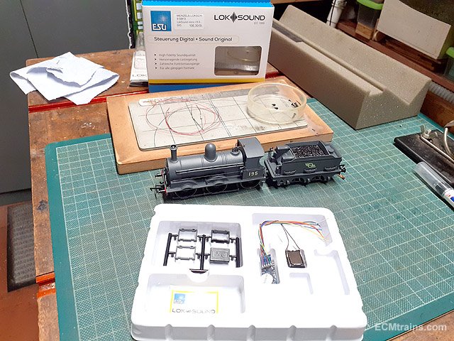
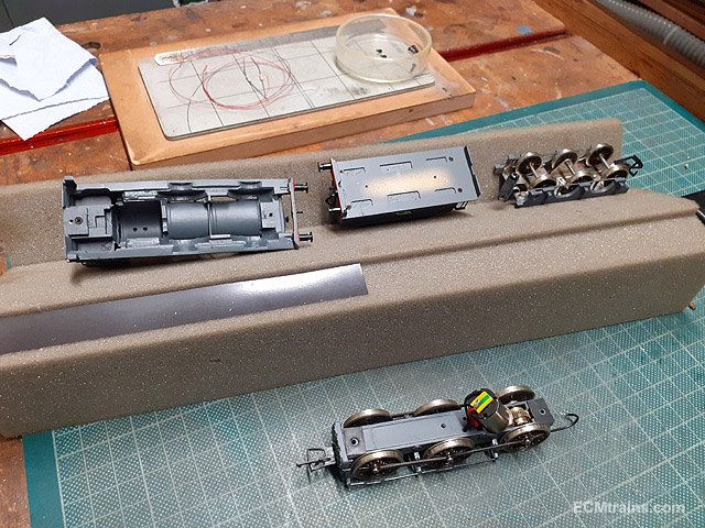
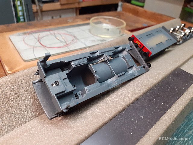
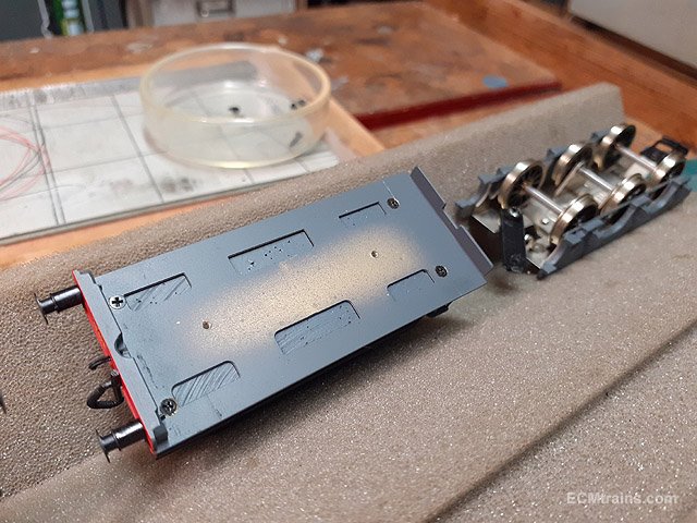
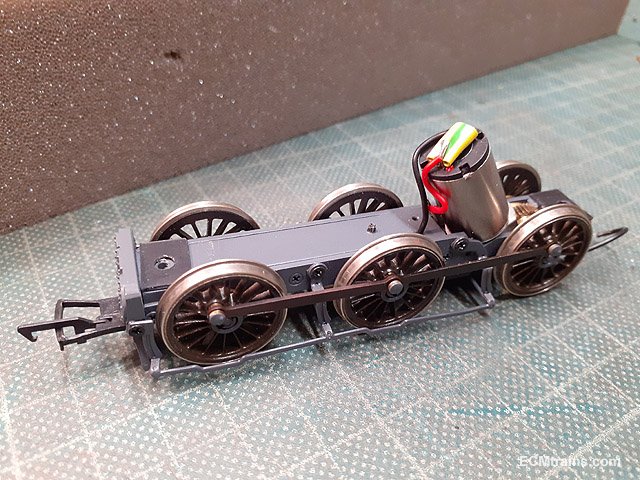
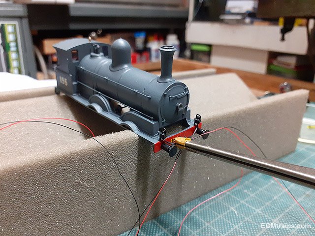
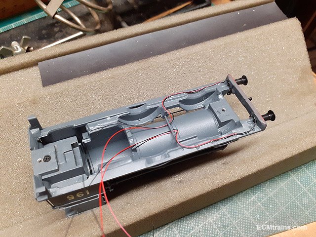
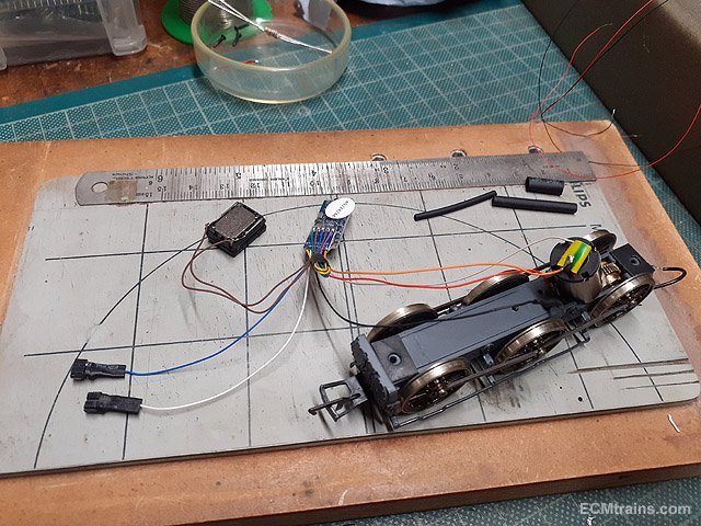
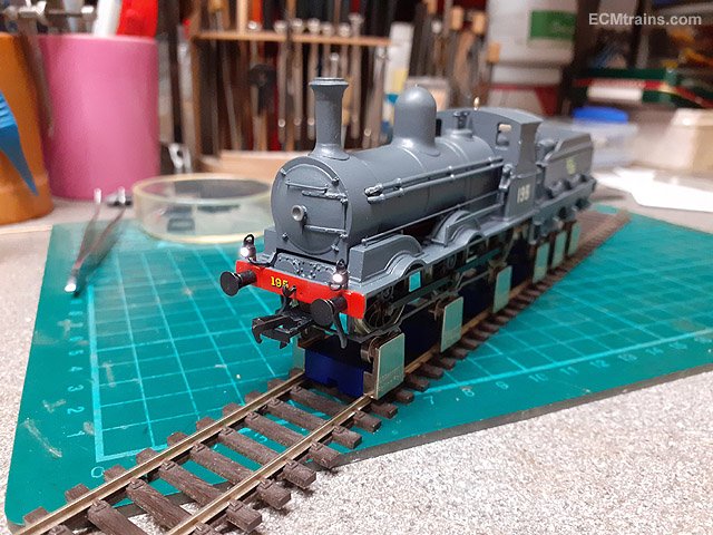
This might be of some interest for chaps thinking of DCCing a OO Works J15;- The bits- the chip is a ESU Micro V0.5 with the standard sugar cube speaker, also being installed are front lantern lights using nano LEDs from JS Miniatures and white metal lanterns. The sound file is from Wheeltappers. The loco bits. The only place for the chip and speaker is in the boiler, a standard ESU sound chip will not fit, it's too wide, so that's why I'm using a Micro. The speaker will have it's cover installed with no risers, this should allow for all the parts n wiring to be crammed in! The tender is a solid block of cast plastic! The chassis- I like the way they built this model, all the major components are in sub assembles, then screw fixed together to make the model. After hearing about the gearbox messing up on these models I took a good look at it- the meshing of the gears on this one is too loose! not doing anything about it now, we'll see how it runs in the future. Smooth throttling will be required! Lights being epoxied on. Route of the wires to get into the boiler. The chip is hard wired to the pickups and motor, the lights will connect with mini connectors so the body can be removed completely, the resistors for the lights are on the LED leads- that's the max I can get into the boiler. Done. 20250916_201857.mp4 Eoin
-
- 10
-
-

-
As you say, most likely rails were laid to move the stones for the second shunt of the wall out to the light ship- which the existing lighthouse replaced. The stones are quite large and the best way to get them out there was by man hands on railed carts........ Edit;- I also remember reading that the stones came from Dalkey, these were most likely barged across to the works from Bullock Harbour, so there may not have been a need for rails for this purpose as they would have been craned off the barges into place. Still could have been used for fill underneath though! Eoin
-
If you tell him you have viewed this video- he will tell you everything! https://www.youtube.com/watch?v=D_on7lzhU_Q
-
The best man for info on the Drumm system is Cliften Flewit (spelt that wrong!) in the IRRS, if my memory serves correctly he told me that one of the 4 wheel test units ended up as a holiday cabin near Bray! Eoin Edit;- Clifton Flewitt
-
The book was by Roddy Ring..... More info on a google search 'Drumm Battery Train' and https://en.wikipedia.org/wiki/Drumm_Battery_Train
-
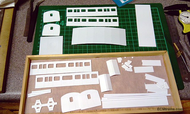
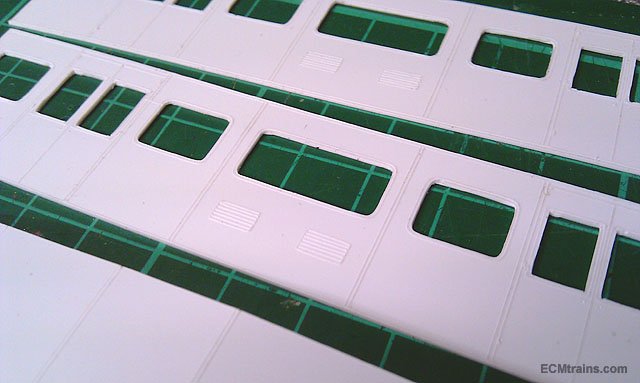
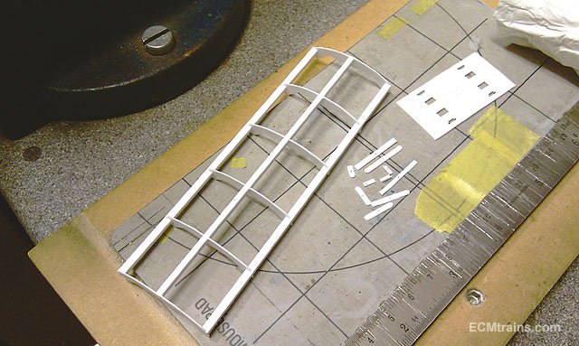
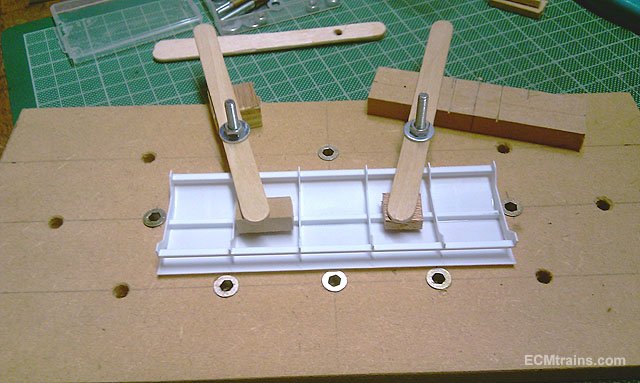
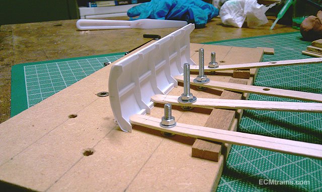
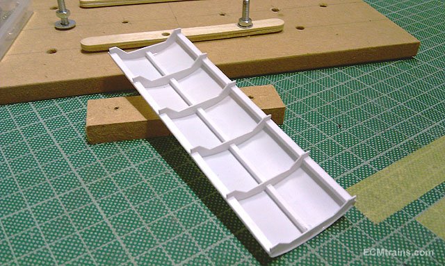
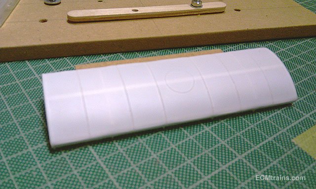
@Galteemore my method;- The polystyrene .5mm ribs are cut out on the Silhouette Cameo cutting machine from a cad drawing, the two outer spars are quadrant shape to give the curve edge on the roof. These are the parts for two vans, cut out and cleaned up. The spars n ribs are glued up- like building a model wing, the ribs are notched to take the spars, and the ribs have a down-stand that notches inside of the coach sides to fix the roof on- one can see this on the bottom photo. The roof covering sheet is cut from .3mm styrene sheet, which is also scored to give the ribbing trim detail on the roof. The roof sheet is stuck down to the central spar first and left to fully dry. Then the edges are turned down over the quadrant, clamped in place and glued. One has to be careful not to use too much glue, too much will melt the styrene roof sheet- it happened on my first attempt! Thats basically it. I built 4 of these tin vans for a client, unfortunately these are the only photos I have of the build, I reckon this was around the time my phone died, followed by the computer back in 2017!! I did make two for myself but never finished them- as John Mayne did another run of his lovely kits, which I bought 2 of- yet to be built...... Eoin
-
Model airplane stuff! I have used model airplane construction method in polystyrene to build coach roofs;- This was for a Tin Van. It would also work with balsa wood. Eoin
- 560 replies
-
- 11
-
-
-
Unfortunately, this project has come to it's end with me, with my lack of performance due to domestic issues over the last 2-3 years the client could not wait any longer. He has sold the model and it's new owner has a chap that will finish it. I look forward to seeing it complete, it's a unique model, and I regret not finishing it myself. Eoin
-
until
-
The September Fair Date;-
-
Where do you get your etched works / loco nameplates from?
murrayec replied to Jamie Davis's topic in Irish Models
You can add sodium hydroxide to brake it down into a liquid of a low pH and a sludge, the liquid can be disposed of in the drain and the sludge has to go to the local authority hazardous waste bin. Thats the other thing doing home etching- one is using hazardous stuff, also the etching process gives off hydrogen gas, not huge amounts but best to have a window open! Eoin -
Where do you get your etched works / loco nameplates from?
murrayec replied to Jamie Davis's topic in Irish Models
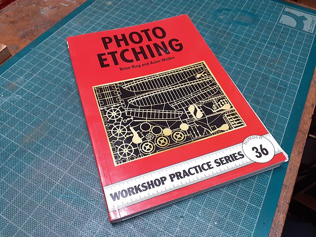
For one or two off items it is best to go to a suppler, there is a steep learning curve to home etching and it takes a lot of trial n error to get it right. This publication is a great introduction;- Most of the materials are inexpensive, except for the UV light box which is required for exposing/transferring the artwork to the resist on the metal to be etched. If one is considering this, stay away from the spray on resist available in the electronic stores which is rather hard to control. Using a film like 'Puretch' is far better and will help to keep your sanity! Eoin