murrayec
-
Posts
2,758 -
Joined
-
Last visited
-
Days Won
70
Content Type
Profiles
Forums
Events
Gallery
Blogs
Community Map
Everything posted by murrayec
-
The January Fair Date;-

-
https://newirishlines.org/
-
Wheeltappers do an ESU one;- https://wheeltappersdccsounds.co.uk/page48/index.html
-
Yes
-
Voltage:- 12 to 24 volt. Controllers;- DCC Roco Z21XL 12-20v 6amp. One needs high amps for some Gauge 1 models so you need to buy high end stuff, the Roco Z21XL is a good starting point but you will need accessories if you plan a large layout or multipal locos - the controller starts at €380 and cost goes up depending on what you add to it. DC Gaugemaster GMC-10LGB5F up to 20V. 5amp. Cost = £280 This could handle 2 small locos! But as per analogue running style a separate controller would be required per track to run multipal locos. Eoin
-
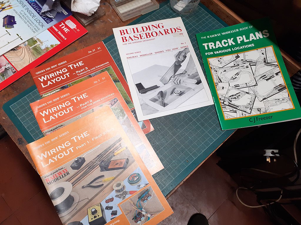
@Adrian bolton You may be able to buy a standard base board in Marks Models if they still have them in stock, if you are going for non standard to fit into the attic you would need to know your track plan and build the boards to suit. Marks Models used to stock these helpful booklets, which could give you an idea on how to proceed;- Give them a call to see if they are in stock? There is also a wide range of books online which are very helpful, some helpful members on here should have more recommendations. Eoin
-
I have one on the way, a McGowan Kit, though I haven't seen it in a while, I think the attic fairies snook it away! https://irishrailwaymodeller.com/topic/6358-gsr-class-551-j26-ecmbuild-in-7mm/ Eoin
- 54 replies
-
- 2
-

-

-
- o gauge layout
- irish outline
- (and 2 more)
-
https://www.airframed.co.uk/
-
Yes, one of my favorites. Eoin
-
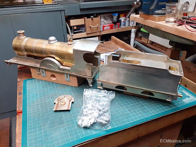
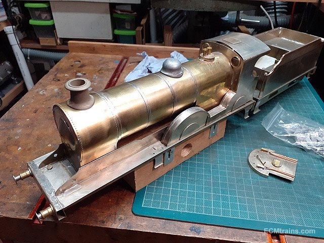
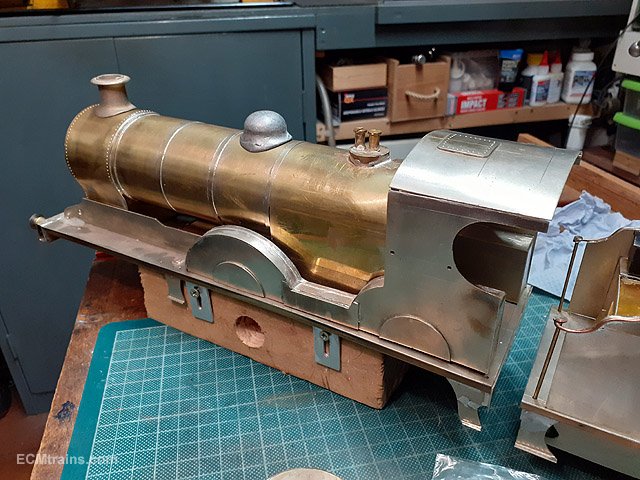
Class 500 G1;- Slieve Gullion 171;-
-
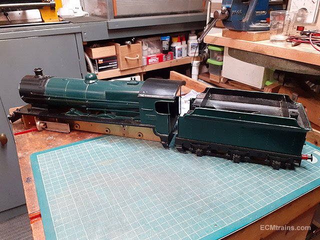
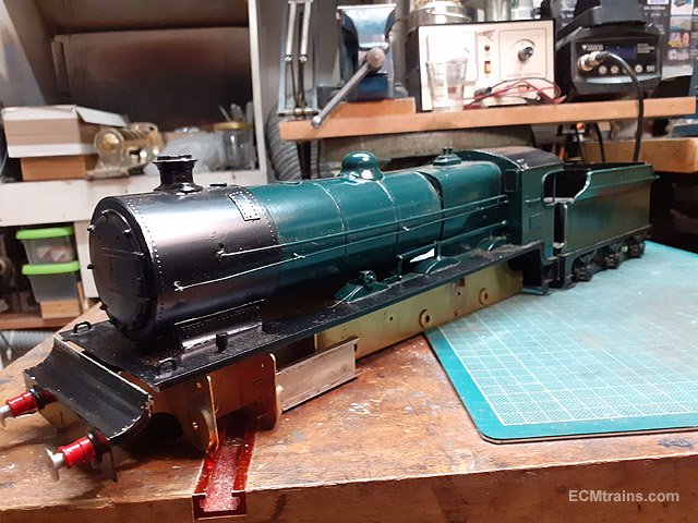
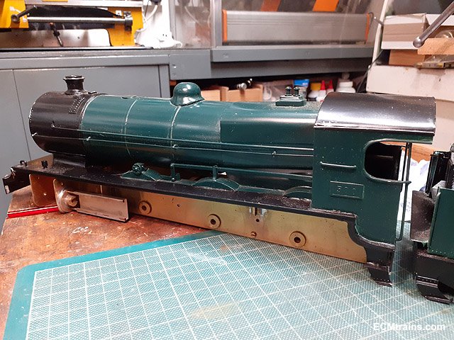
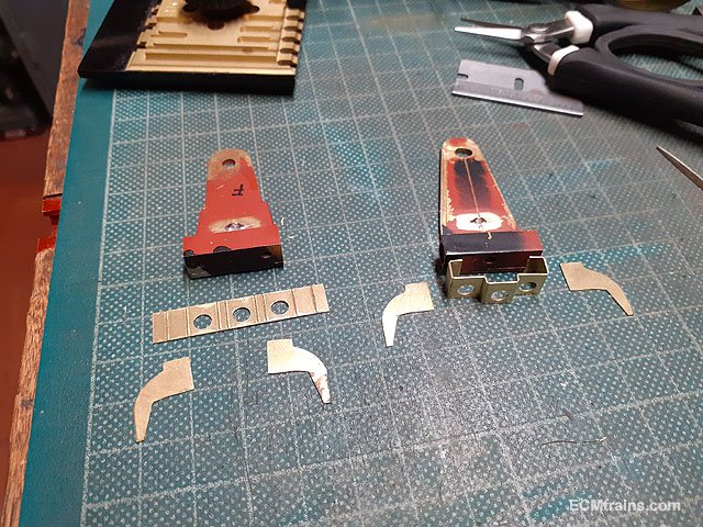
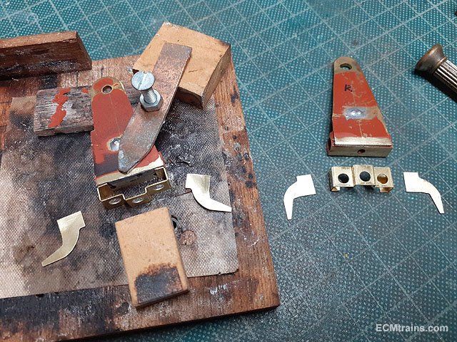
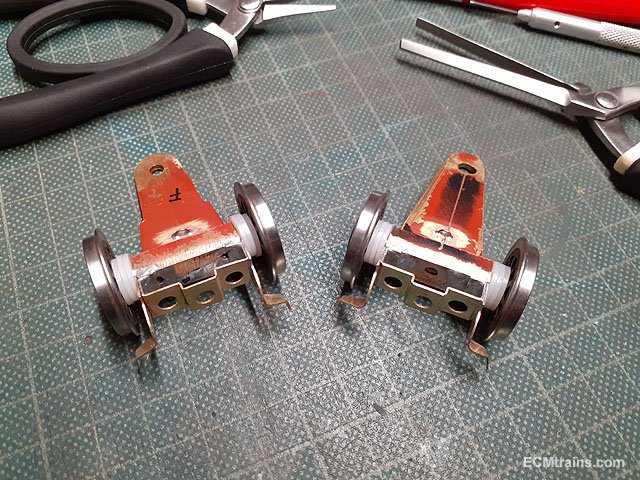
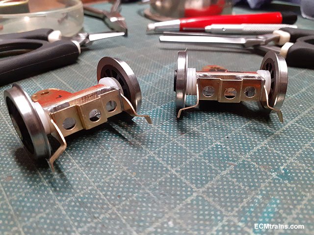
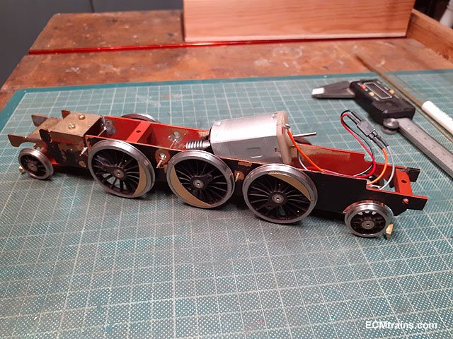
Continuing on 850 after another stall due to family issues;- The pony truck detail parts cleaned up, ready for folding and soldering. Jigging. Soldered up and the guard irons bent into shape. Multipal plastic washers installed to center the axles on the trucks. Trucks test fitted and .4mm NS wire electrical wiper pickups installed. Motor wired up and almost ready to give it a test run, except for the rods, crosshead n valve gear which is next..... Eoin
-
until
-
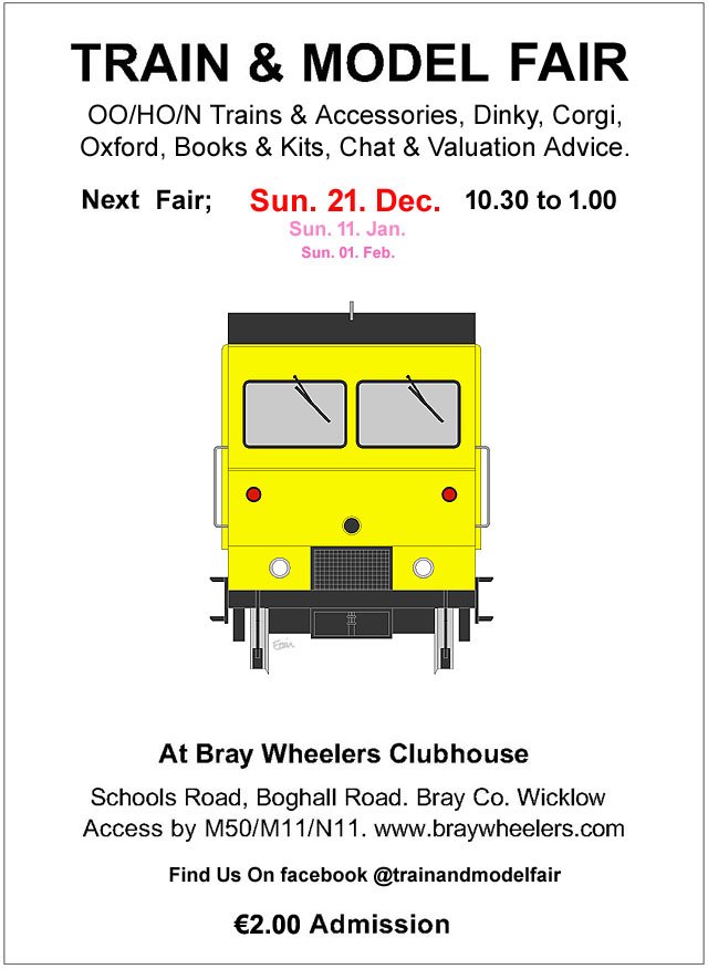
The December Fair date:-
-
https://www.hattons.co.uk/17798/hornby_r8675_modern_lineside_building_aws_box_set_skaledale_railside_range/stockdetail
-
Air dry clay needs to be done on sealed surfaces in small sections to avoid cracking, like laying the real thing! Card is much easier and it can be painted with varying shades of grey, again it can be marked/embossed with pencil lead to imitate construction lines. See link to the Greystones layout timber yard below;- Eoin
-
https://mullenslaurelpark.com/catalogue/9d22e715a6e7d7c91bc03c1c1c1a3535/8d18a33c49d230f6f512e23c3c7b4265/the-lord-oneill-collection-of-railwayana-live-online-auct/?currentPageNo=1
-
Planning permission works this way;- A decision to grant planning is first made by the planning authority, it's is then open for a period of 1 month for appeals or objections on that decision to grant, if no appeals or objections have been lodged in this period then the final grant of permission is issued. If appeals or objections are lodged in the 1 month period after the decision to grant it then goes to An Bord Pleanala to make a final decision- taking anywhere from 3 months to years sometimes, the time is at the discretion of the Bord. Eoin
-
until
-
November's Fair Date;-
-
Yes, everything that Brendan does is superb, same goes for Tony..... Eoin.
-
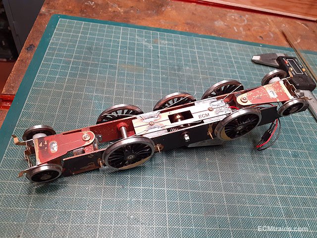
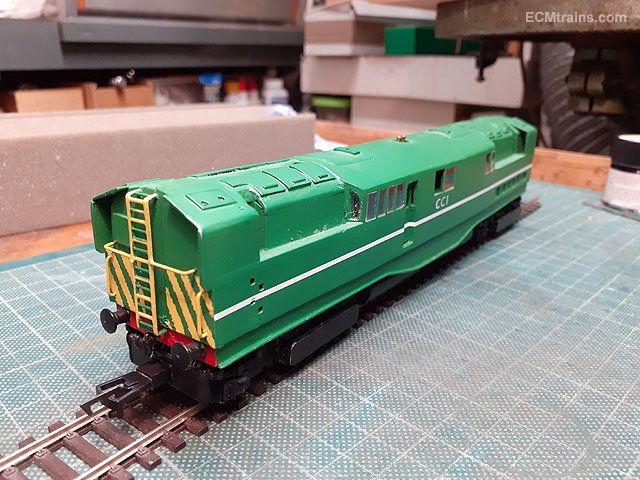
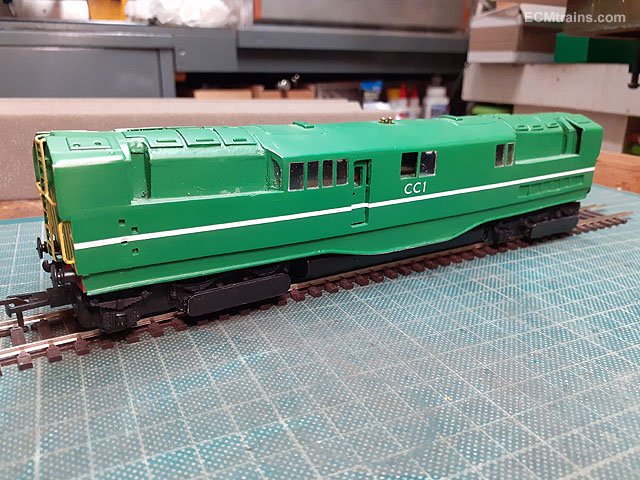
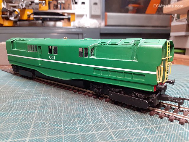
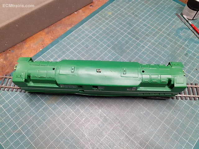
CC1 in the workshop for some repairs. Built by Brendan Kelly & painted by Tony Mrolo, it's on an Athern chassis...... Eoin.
-
Congratulations on the very nice article in Railway Modeller's Special 900th Anniversary Issue, it's all the better getting written up in a special issue- maybe a cover to be framed for your workshop wall? Eoin
-
Thats a 141 kit, in the photo the cab sides are missing- unless they are stuck onto the cab fronts as the fronts seem to be propped up on something..... Eoin
-
 Hi Callum, Thats unfortunate there is no scale given. All draftsman should indicate a scale on drawings. Thats a sectional detail drawing you show, sometimes these can be drawn full size, my comments above related to a full loco general arrangement drawings or say a drawing of the chassis only. But I see figured dimensions on that drawing, so you need to get out your scale and measure the dimensions to see what scale the drawing is. I hope you are familiar with using scales and have a few, the dimensions are imperial so you need an 'imperial scale' Eoin