murrayec
-
Posts
2,770 -
Joined
-
Last visited
-
Days Won
70
Content Type
Profiles
Forums
Events
Gallery
Blogs
Everything posted by murrayec
-

Can Anyone ID This Leinster Models 0-6-0 Kit?
murrayec replied to murrayec's question in Questions & Answers
@Galteemore yes, that is looking more like the kit, and the SR Class Q appears on the Leinster Models kit list. Thanks Eoin -
Can Anyone ID This Leinster Models 0-6-0 Kit? I'm told it could be a LSWR 'Black Motor', but photos online show a round top firebox and different cab front windows! Anyone know? Eoin

-
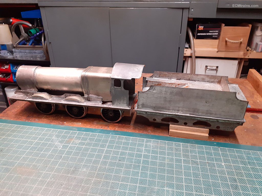
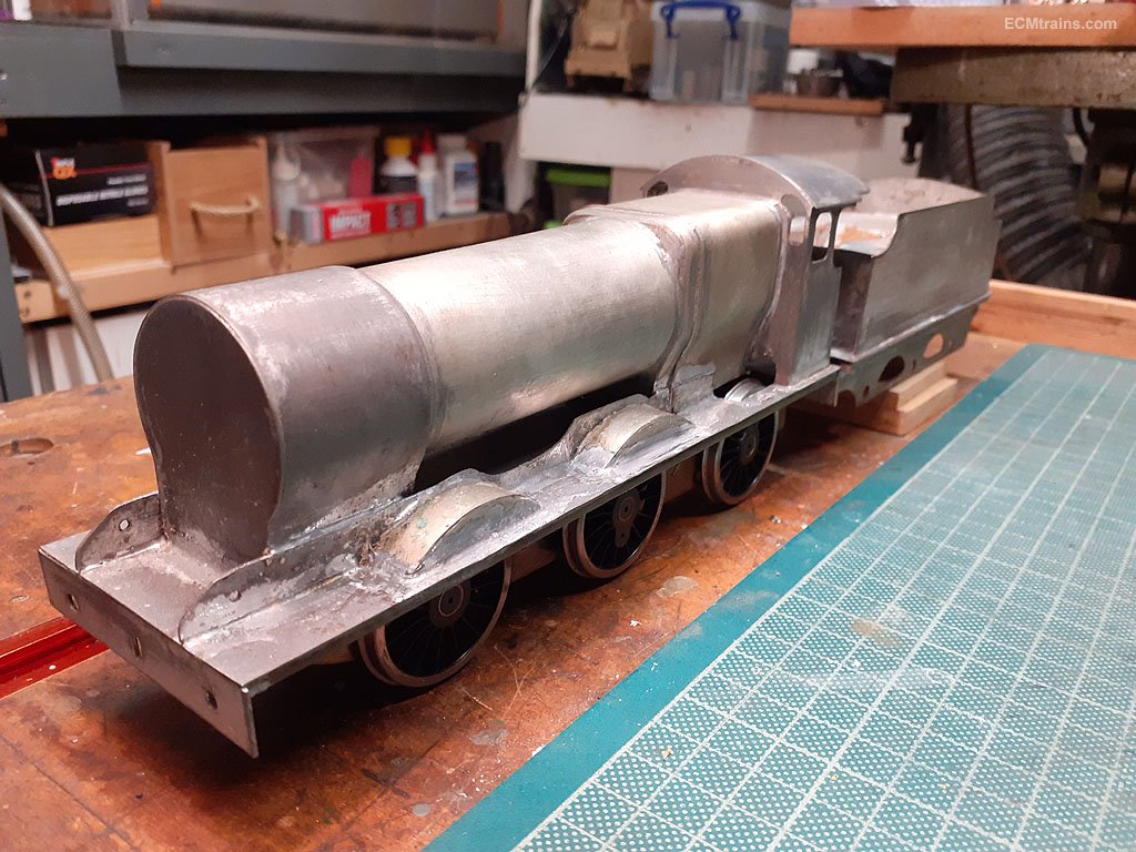
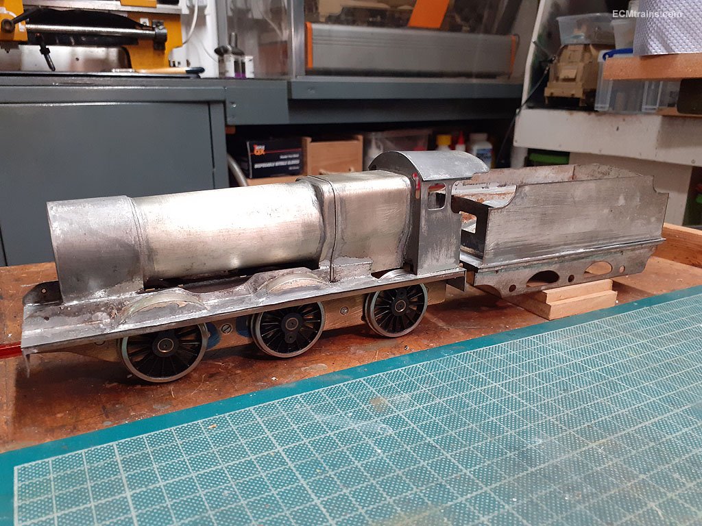
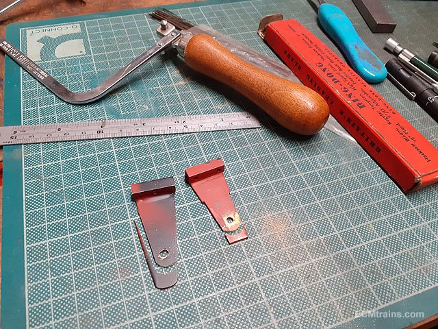
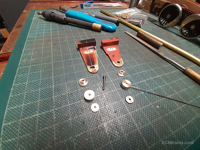
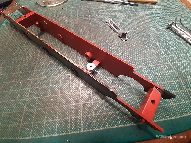
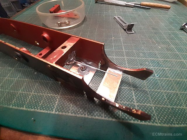
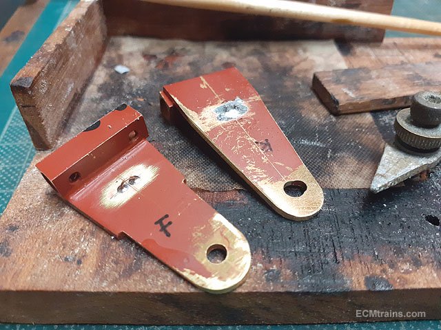
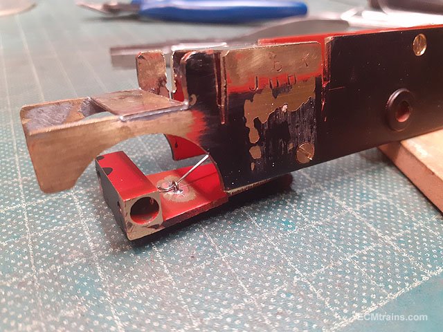
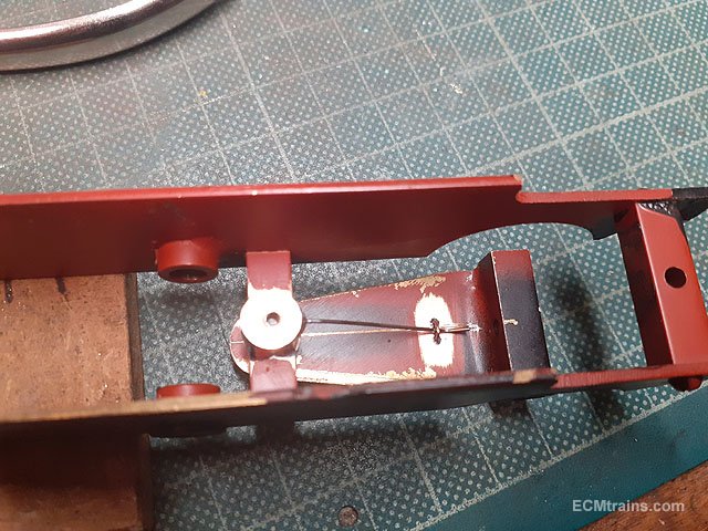
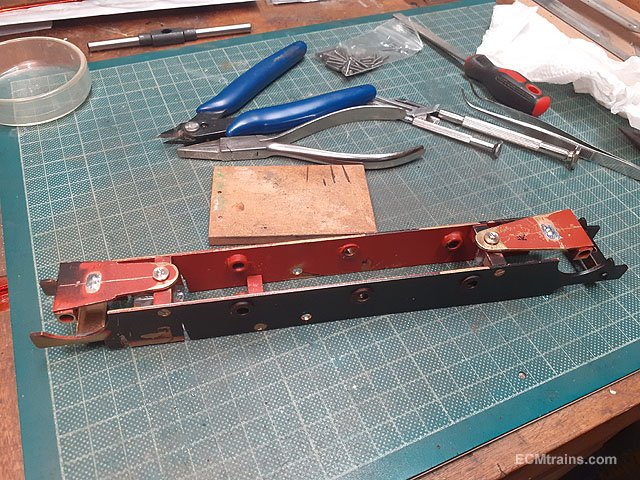
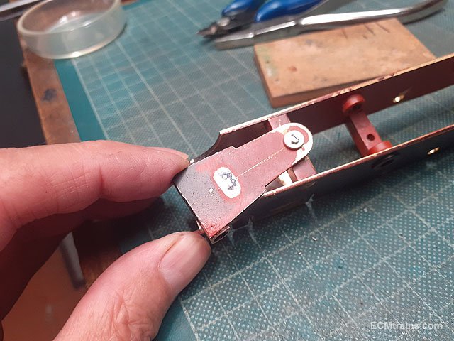
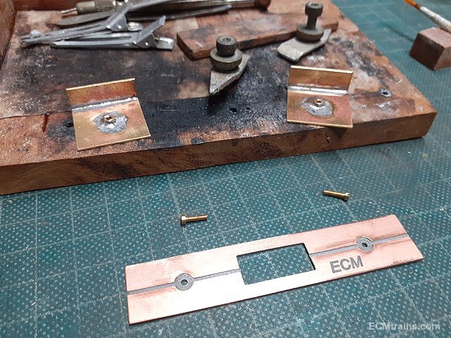
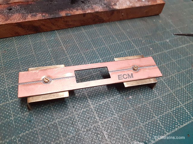
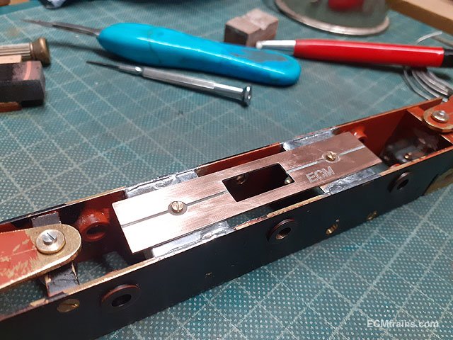
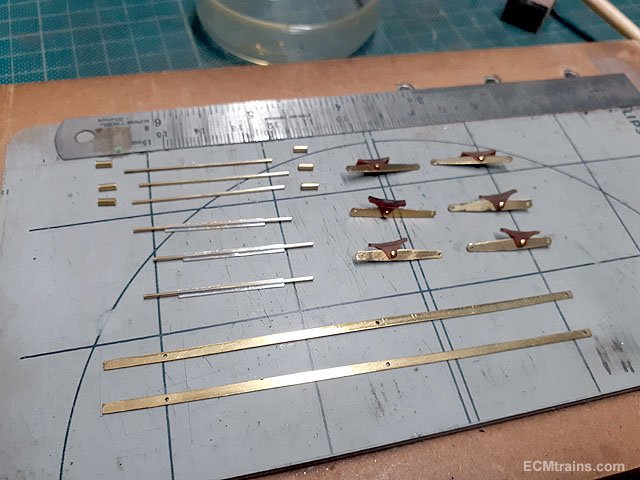
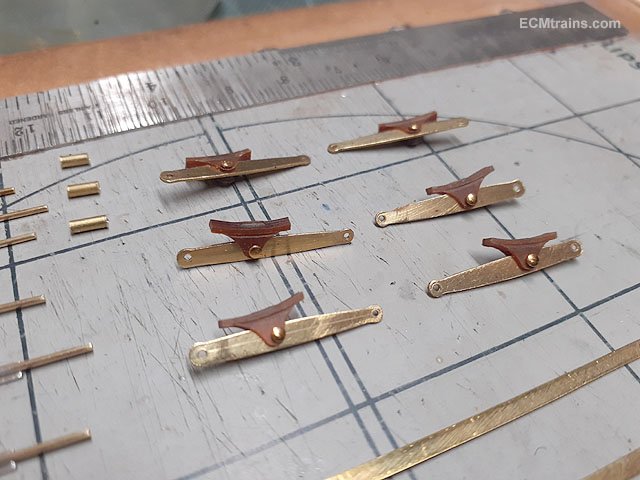
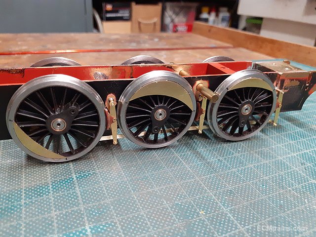
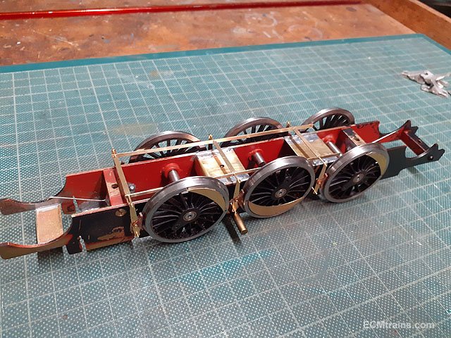
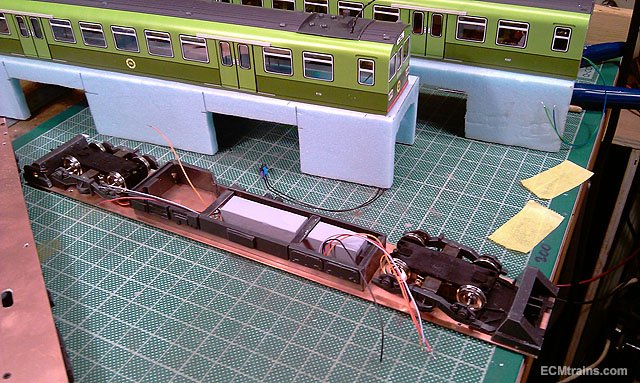
Setting up the bogie trucks, elec pickup board and brake gear;- The existing truck frames being modified. All the truck pivot parts turned up on the lathe, the circular nuts are drilled to hold .6mm NS wire centering springs which work on the little brass wire hoops fitted into the truck frames. The trucks will pivot on a brass bush. Nuts and wire spring parts soldered onto the frame spacers. Brass hoops being soldered onto the truck frames. Centering springs are bent to shape and the trucks trial fitted, the trucks pivot on a brass bush screwed fixed through the frame spacers. Pivot being tested, the truck frames need a slight bend just before the pivot- later! Done. Electrical pickups- 10BA nuts are soldered onto the folded up brass frame spacers. The board is a bit of .8mm PCB board CNC'd previously. The BCB board is fixed to the frame spacers with 10BA screws to hold in position when soldering the spacers to the chassis frames. Soldering complete. All the parts for the brake system setup. The brake blocks are CNC'ed from Tufnol and pinned to the hangers with .7mm brass dress pins. Brake parts test fitted to the chassis. A few mods are required before soldering, that's for the next installment...... Eoin.
-
Hi @George, That Hornby is not a reliable controller, I would recommend you go for a upgrade if you can. If the SJ 1200 is DCC fitted and set to run 'Analogue', it will run with that controller. If not set to run analogue or cannot be set- no chance on that controller. If it is DCC fitted, the way to control the models digital functions is with a DCC controller, so if upgrading the Hornby R8250 go for a DCC controller.. Roco Z21 or Multimaus, etc..... Eoin
-
British locos and stock that can be disguised as Irish
murrayec replied to Westcorkrailway's topic in Irish Models
You need a set of these...... Eoin
-
until
-
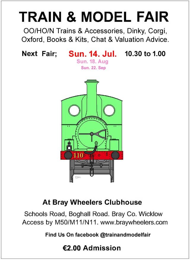
The August Fair Date;-
-
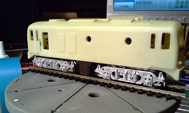
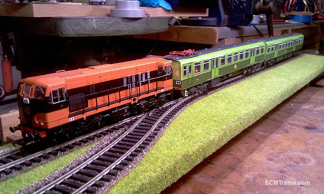
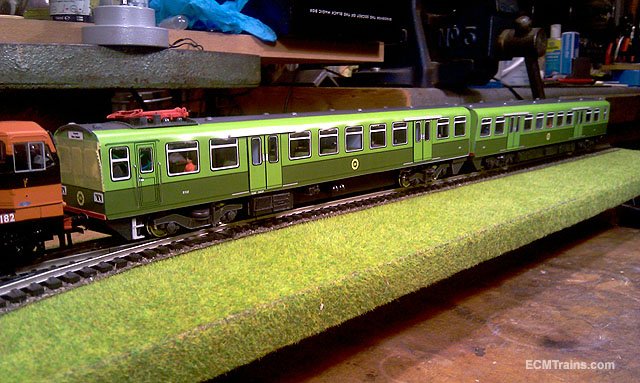
Unfortunately I lost the majority of the files on this project, back in 2021 my computer died and I could only restore a few files! the ones shown above were restored from this forum. I will be setting up a sound one for myself and will show a video then, or if I meet the client of the above one I'll get some video. Again those photos above are all I could restore, the loco was renumbered to '143' which was the running number of the actual 141 used. Eoin.
-
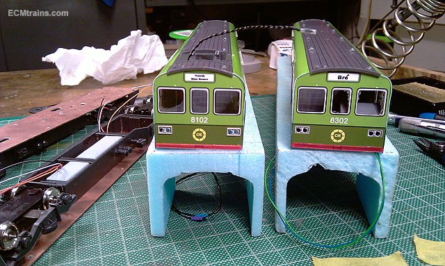
I modeled her sister 8102 in Transition Mode - Driver training;- ..... and the completed model behind it 141 engine This model also has sound, it can run in 141 or Dart mode Eoin
- 24 replies
-
- 11
-

-
I saw! that was coming, though I think I will stick with what I have. It's a year (wow!) since I posted on this project! The shed is fully insulated and waiting to be sheathed out inside, I'm going to use the timber I originally bought to build the shed to do this. Other projects have taken up my time! but should get it done soon...... Eoin
-
Wizard Models Ltd do brass rivet strips and other stuff for wagons;- https://www.wizardmodels.ltd/shop/wagons/mt163/ Eoin OOPS! just saw Roberts post!!!
-
NCC WT class from Hornby LMS Fowler class 4, 2-6-4 tank
murrayec replied to gibbo675's topic in Irish Models
To tag a username- type an '@' and then the user name, a menu will pop up while typing, offering usernames, you can select from that also. Eoin -
until
-
July Fair Date;-
-
I like the weathering on the second last image! Eoin
-
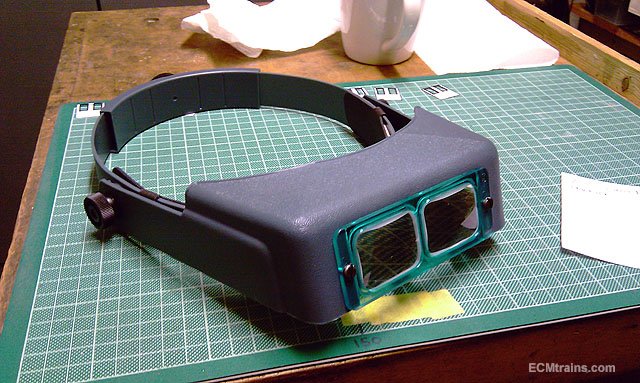
I use a OptiVISOR head magnifier, they have ground glass elements, far more superior than the plastic ones. Though, they do come at a higher cost. Eoin
-
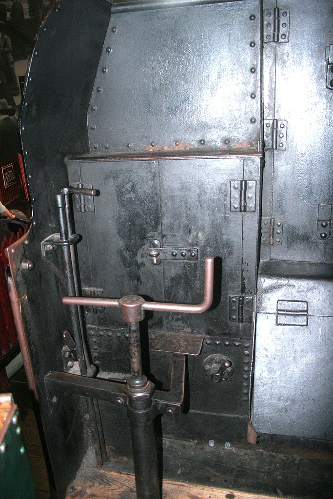
I assumed they were galvanized? Eoin
-
A 3d printed 800 class for 00 (and a WLWR goods loco)
murrayec replied to Killian Keane's topic in Irish Models
Hope these help Eoin
-
Very sad, rest in peace
-
Very sad news, a great modelling friend and yes a perfectionist, I will miss him to. Eoin
-
until
-
The June Fair Date;-
-
Check out John Mayne for Tin Van kits, not sure if he still has some left, these would be an ideal starting point and a very nice kit.... Eoin
-
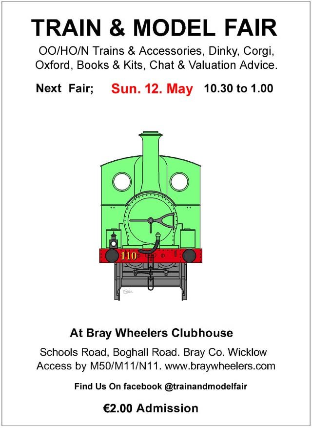
May's Fair Date:-
-
until