murrayec
-
Posts
2,718 -
Joined
-
Last visited
-
Days Won
70
Content Type
Profiles
Forums
Events
Gallery
Blogs
Store
Community Map
Everything posted by murrayec
-
There was 3 turntables, can be seen above on the branch leading to the two story workshops, which had a lift to get stock up to the second floor! The turntables at that time were only 10 foot long, locos and tenders had to be rotated separately. Eoin
-
I hear Eileens Emporium have shut down It's a pity they carried great stock, especially in metal sheet & section Eoin.
-
Stunning Excellent work David Eoin.
-
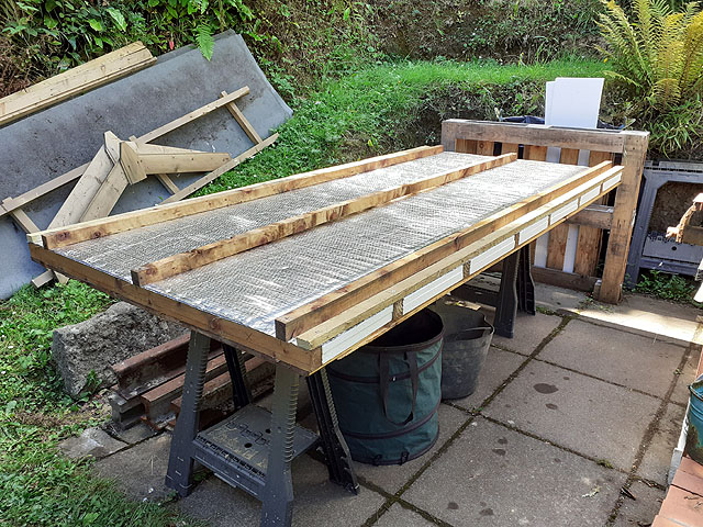
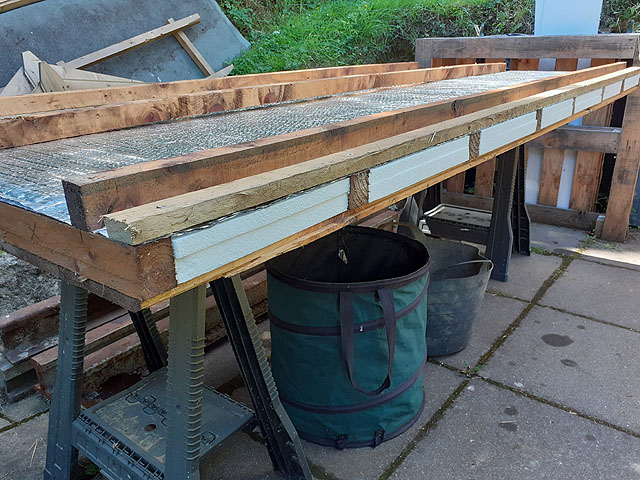
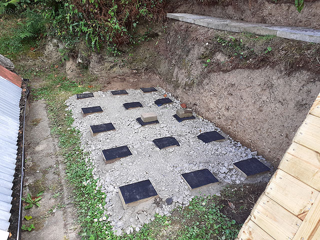
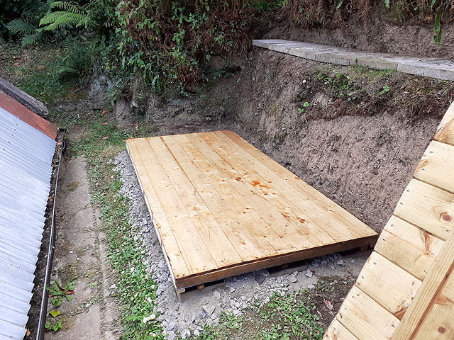
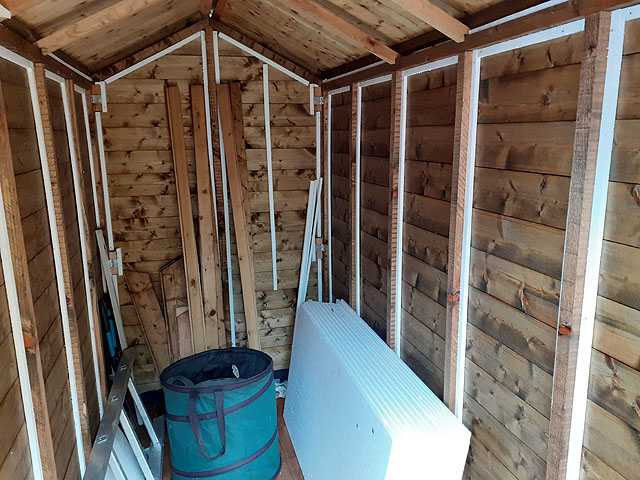
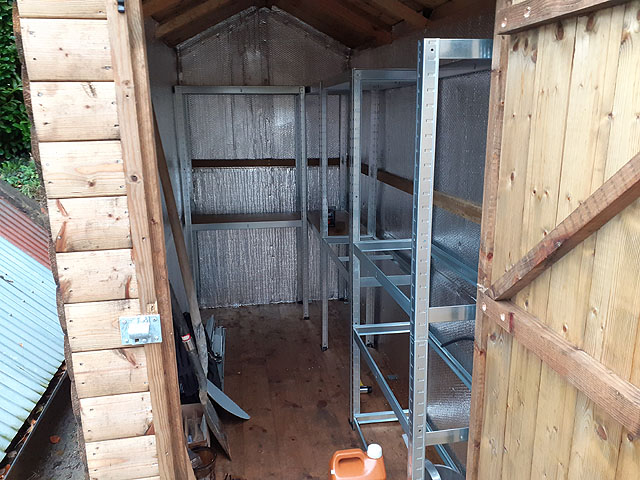
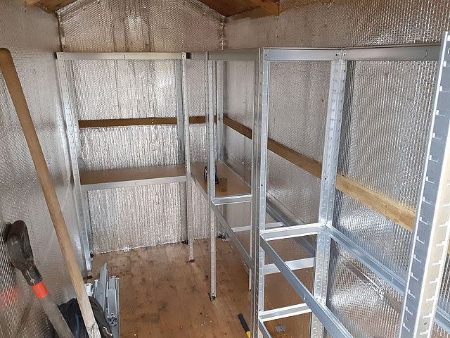
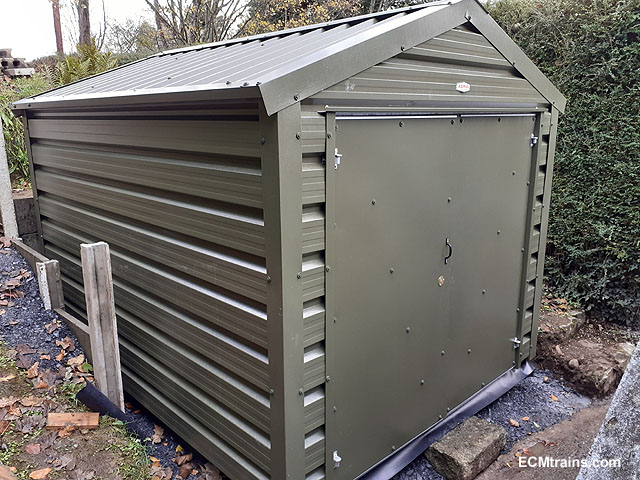
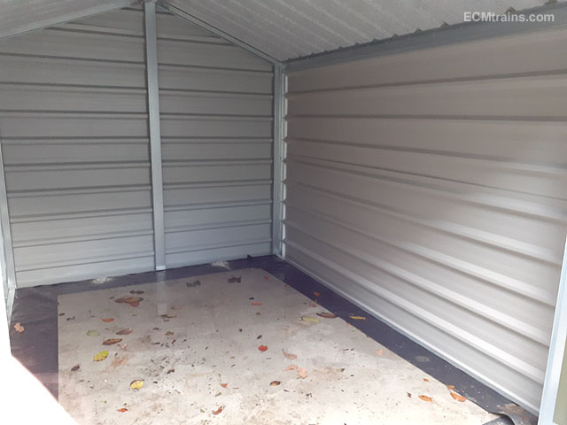
Photos of the 'Shelving Shed' It's your common 2.4x1.2m timber garden shed with tar sheet roof, tight headroom and a 'Duck' door head. All the timber was liberally oiled with Creocoat and then a few mods were made. The floor was insulated with aeroboard and silver stuff- the floor is upside down in the photos. The ground was prepared by removing the sod, levelling with gravel, installing level bricks with a bit of dpc stuck on top. Floor down sitting on the dpc/bricks. The walls up, their sitting on a dpc dressed down over the floor and will be carried up the inside of the walls. the walls were screw fixed with galvanised steel L brackets- so easy to dismantle if needs. I added a few roof frames to give extra support to the roof- these type of shed roofs always droop in the middle! Aeroboard being installed in the walls. Not much room here, I want an air gap behind the wall sheeting so I installed 12x12mm strips adjacent the studs and then fitted 18mm boards on top of the strips- flush with the inner face of the studs. Silver stuff was then installed on the walls, the ceiling will be later as I am insulating the roof on the outside and finishing with corrugated iron sheeting, so holding off silvering. Shelving going in, Yet to do the electrics and the roof...... Eoin.

-
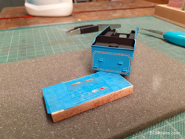
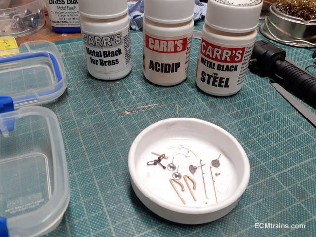
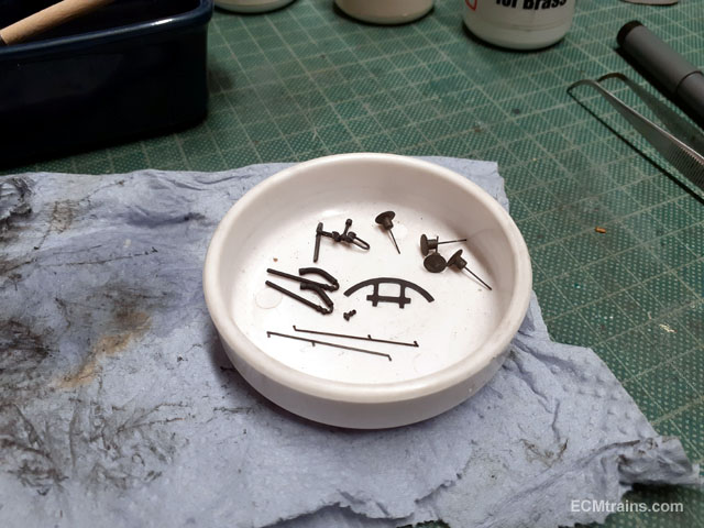
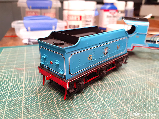
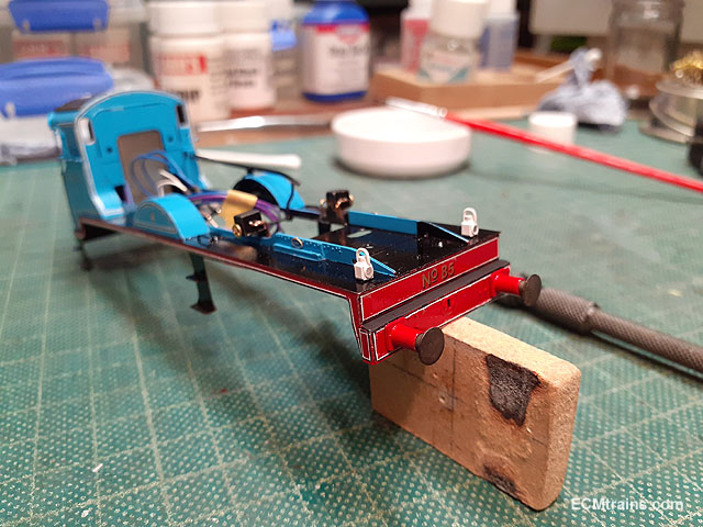
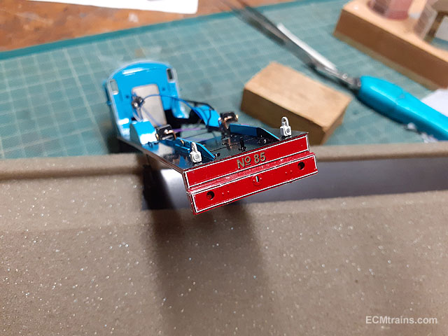
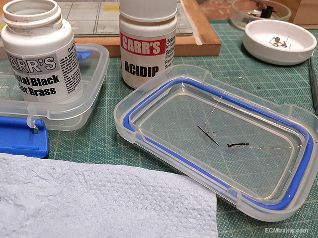
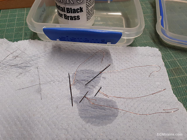
More decals & stuff;- The tender's red makers plate about to go on with Pledge floor polish! Buffer stocks being epoxied on. Blackening some of the final parts. Black. Smoke box door handle epoxied on. Ready for a few paint touch-ups. When doing the touch ups and installing the buffers the decals were coming free, I'm going to fix and wash them over again with Micro Sol, then lacquer the parts, do paint touch ups then, and lacquer again....... Eoin.
-
-
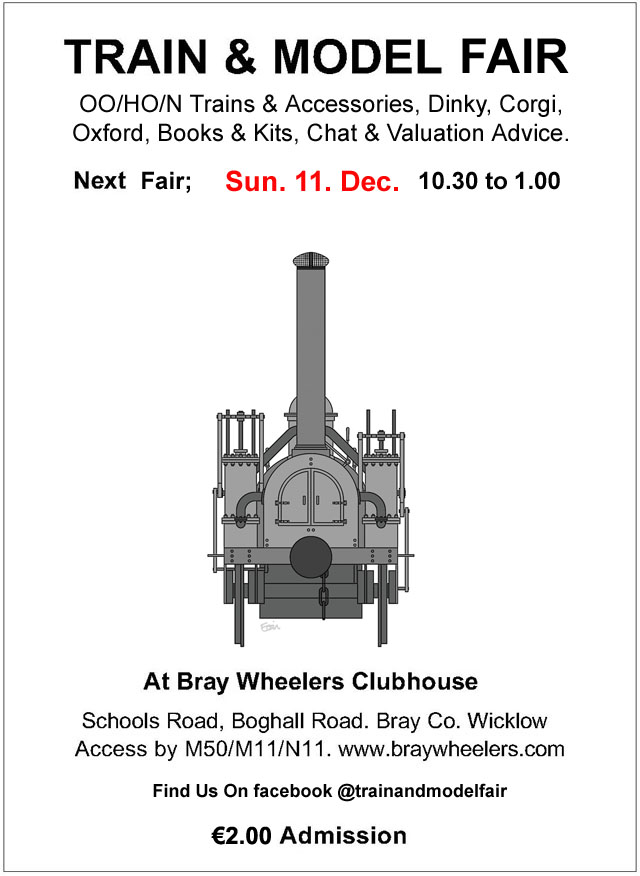
December Fair date;-
-
Hi Dan 1.) A few possibilities here;- 2.) That would depend on what stock you start with- some have wide enough W irons that allow 21mm and some don't, filing the inside of the irons may allow for 21mm if the stock has enough 'Meat' - others don't, so the irons could be cut off and re-glued to create space. 3.)Mayner and KMCE on this forum are producing some kits, have a look at posts in this link;- 4.) That's a lot of work for starting out, especially the chassis mods for 21mm - Worsley Works do a body scratch aid for the jeep but needs a lot of input from the builder! Eoin
-
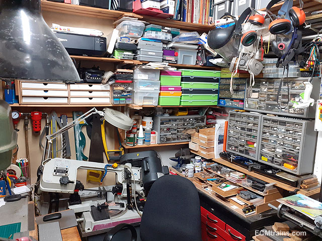
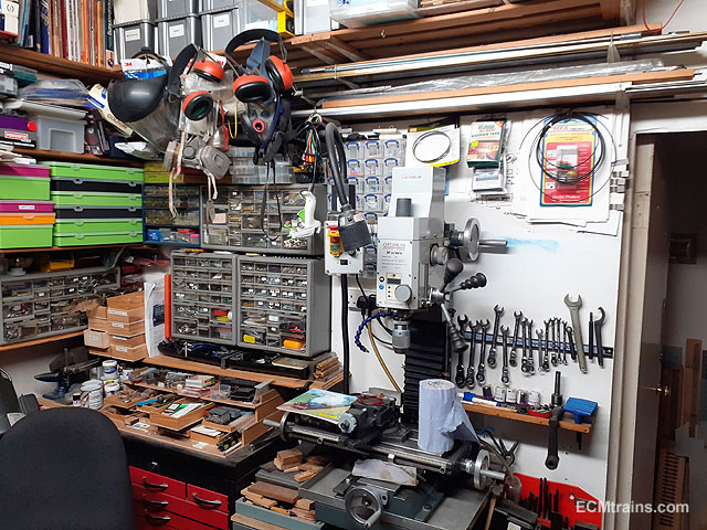
Yes I do the same, a lot of my tools are mounted on an MDF board which are clamped down like your photo above. I use ujktechnology.co.uk T slots and clamping system on the low workbench which takes most of these mounted tools. Eoin
-
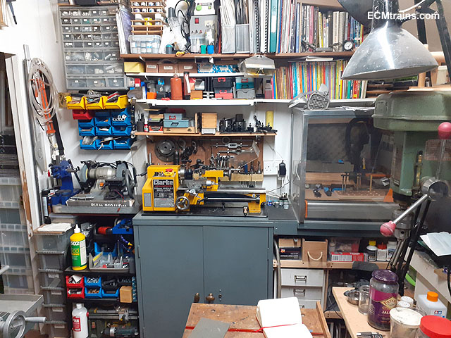
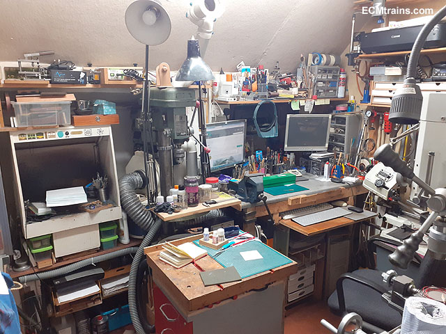
'Shelving' that's my main problem in the workshop, none left! Other tools and equipment are stored in the attic and the 'Coal Shed' both full to the brim! Hence the need for a 'Shelving Shed' Eoin.
-
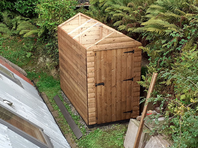
Excellent, I have another shed happening as well as the 'Lathe Shed' I'll post up a few photos soon- this one is a timber 2.4x1.2m shed taken from my brother's place and am using it for shelving storage to keep the Lathe Shed as clear as possible. Eoin.
-
The shed arrived last weekend Next will be insulation inside all-round, timber roof and wall sheeting, electrics, and move in......... Eoin.
-
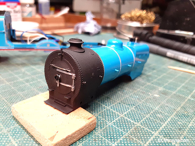
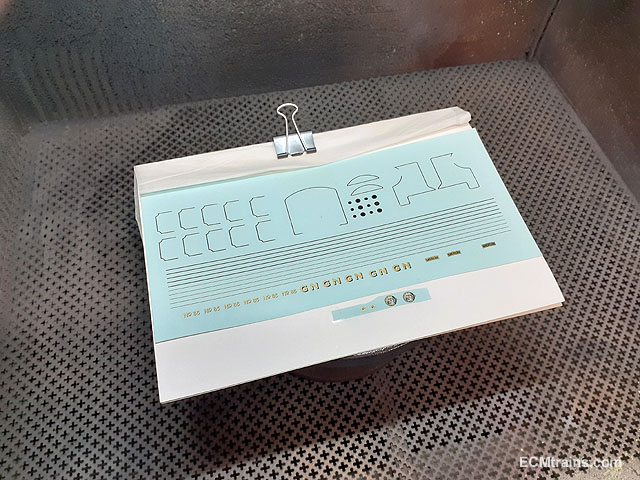
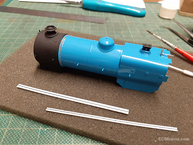
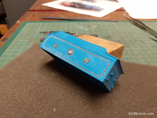
Decals going on- this is not for the faint-hearted or anyone with a pacemaker! The kits decals have some very fine lining and the sheet supplied with the kit had damage, so I sprayed some lacquer over them to try and hold it together. I also ordered a new sheet should disaster happen- and it did! 3 coats of satin lacquer applied. Started on the boiler first, strips of the lining were cut from the sheet and applied by wrapping the decal on the backing paper around the boiler, then applying water with a paint brush, encouraging the decal to slide off onto the raised boiler detail. The decals still broke up but with patiences I could get the bits to line up, overlaying small cut strips on top of the bad bits also works. The cab sides and the valance decals were cut into sections and applied, these will need some touching up. Same again on the buffer beam. I'm still waiting for issue of the valance decal sheet, described above some time back, to finish the back-end of the valance. This lining is tiny and brakes up into many bits! A few more bits to go....... Eoin.
-
I would use 2mm piano wire, as the drive gears need to be glued onto the new axles with Locktite- Locktite works best on steel rather than on brass. Eoin
-
Happy Birthday Wrennie Lots of Love, Eoin
-

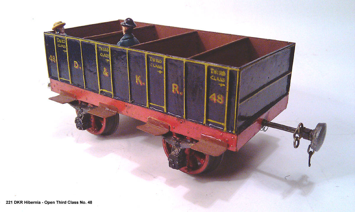
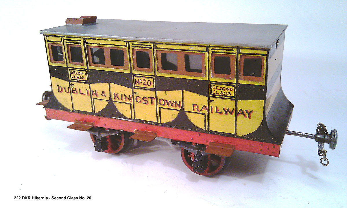
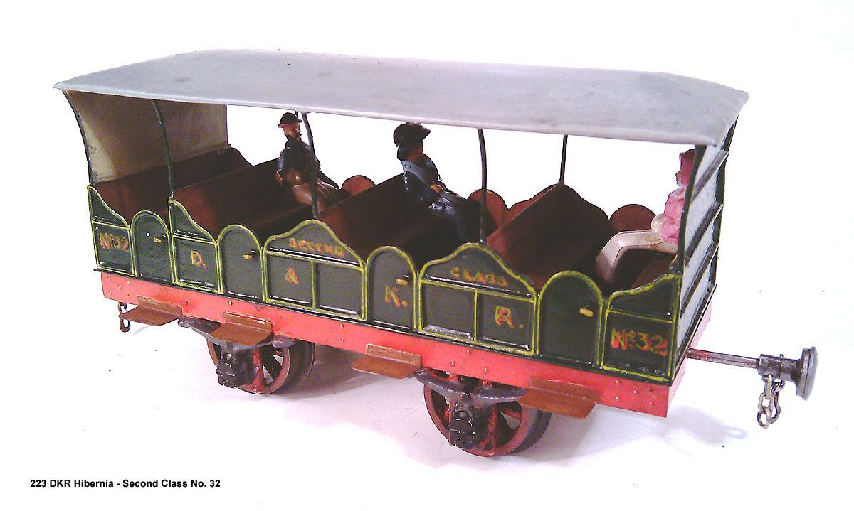
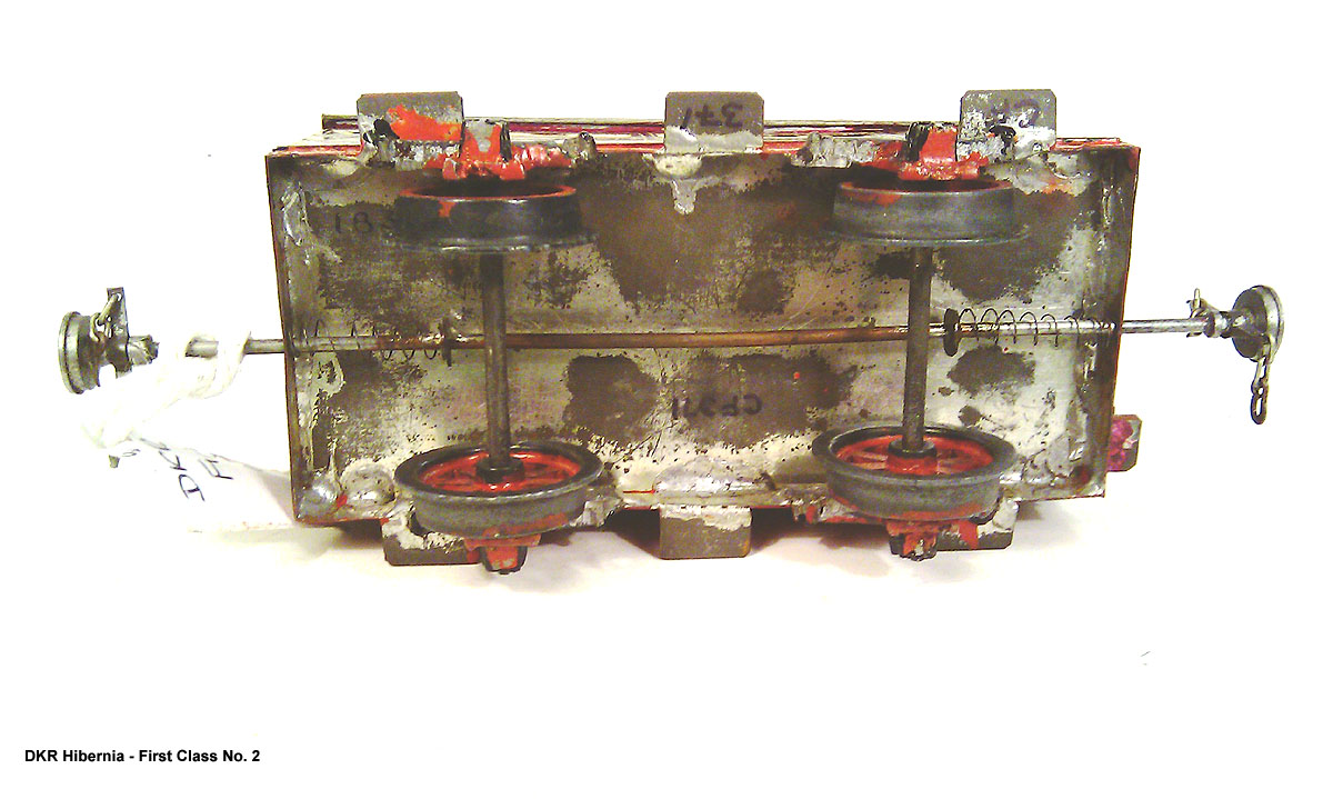
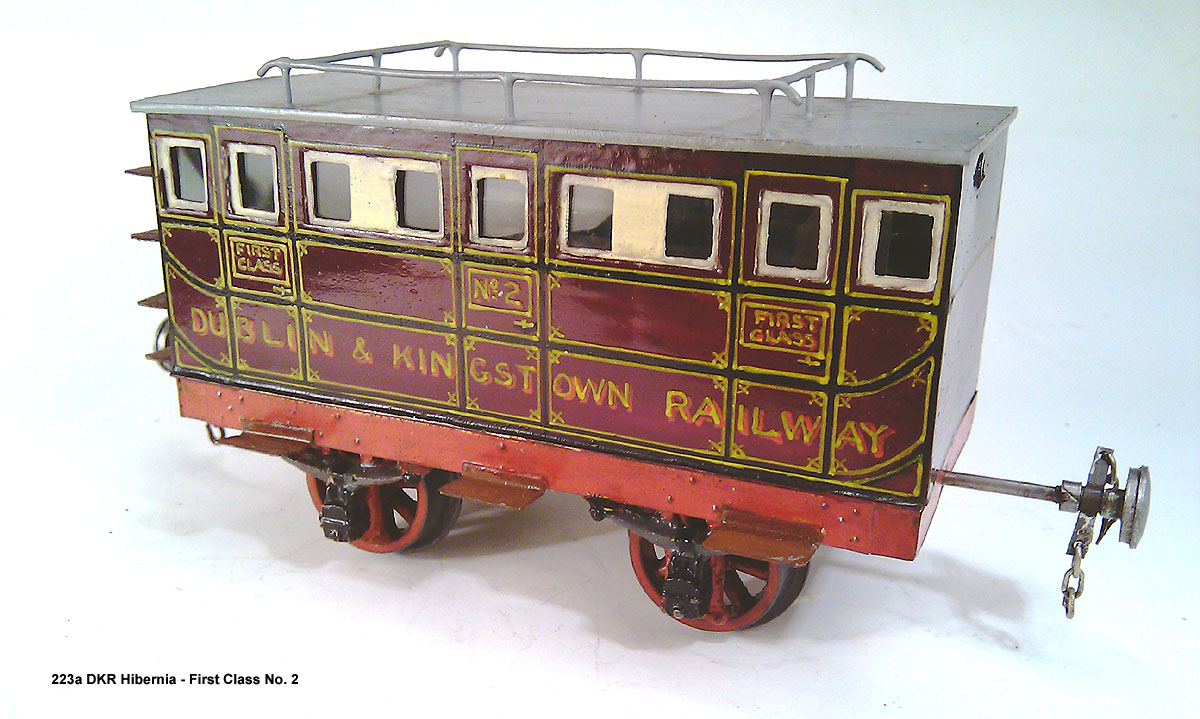
Two Axel Coaches in Ireland?
murrayec replied to Auto-Train Original's topic in Photos & Videos of the Prototype
Mr Fry's Dublin & Kingstown Railway 2 axle models;- Eoin.
-
@Dave Dawes You will have to replace the axles, the 141's axles are flush with the face of the wheels for 16mm track You may be able to push the wheels out on the existing axles- they will be overhanging though! Eoin
-
It came by truck and we had to bucket it in, up six steps to the patio level. Hard work but I had help. Eoin.
-
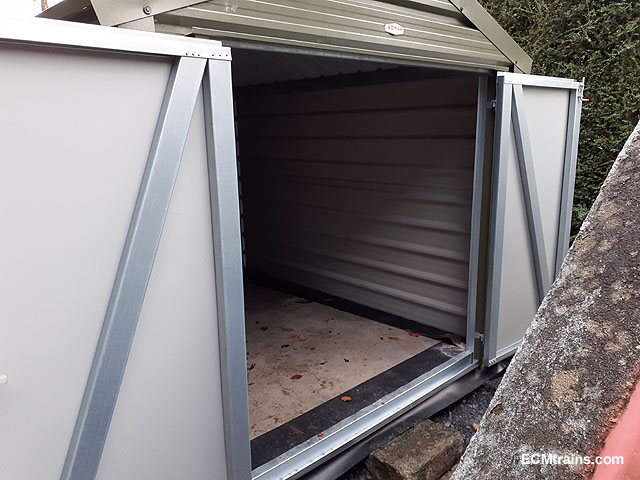
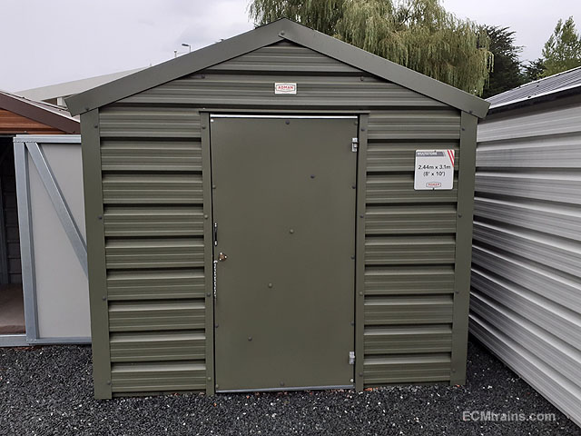
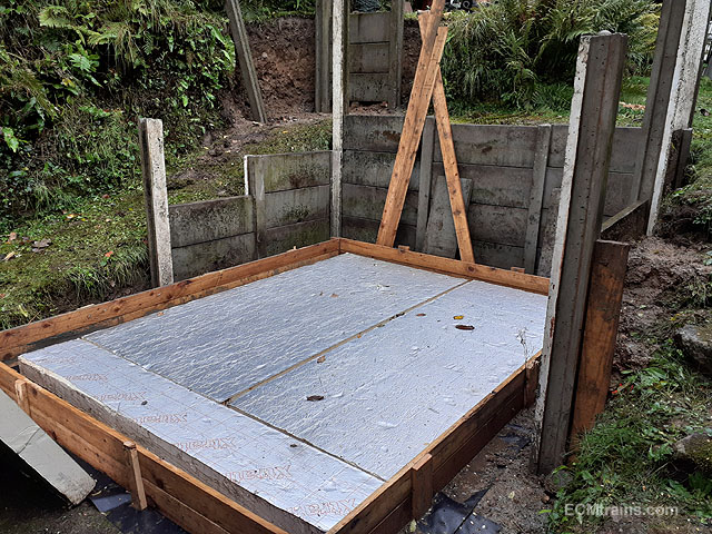
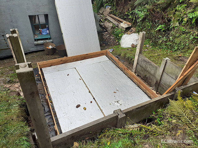
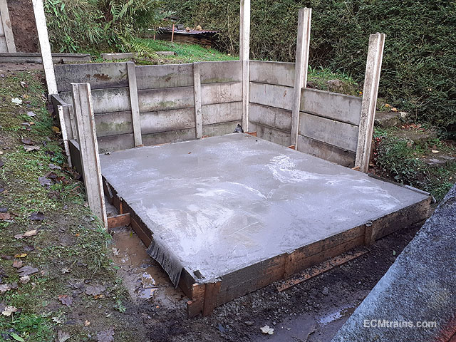
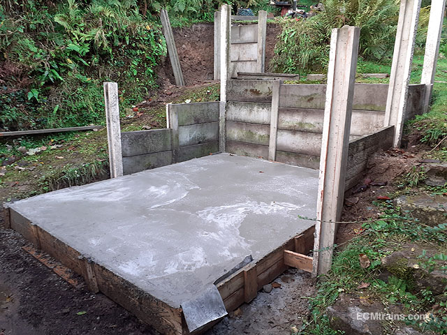
A bit of progress on the Myford project;- A very nice man has donated a metal shed for this project, I'm doing a reciprocal service for him. He insisted on providing a metal shed rather than using the wood I bought last year to do it. This is the type, but mine will have a double leaf door. After cutting out more of the bank around the patio we installed a type of retaining wall, consisting of pre-cast concrete fencing system to stop the clay falling against the shed walls. The long posts will allow for installing handrails to the ramp and steps- that at a later stage. DPM & 100mm floor insulation was laid on top of the patio slabs and timber shuttering was constructed for pouring a 100mm thick concrete floor slab. The concrete floor was poured last week, it was very hard to get a smooth surface finish because of limited access due to the retaining walls, so some remedial work is required- a floor levelling screed may be used after the shed is installed. The shed is due in a week or two? .......and yes, there will be some form of layout installed around the walls, Gauge O & 1 test tracks! Eoin
-
November Fair Date;-
-
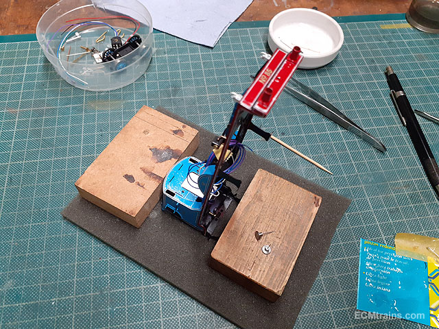
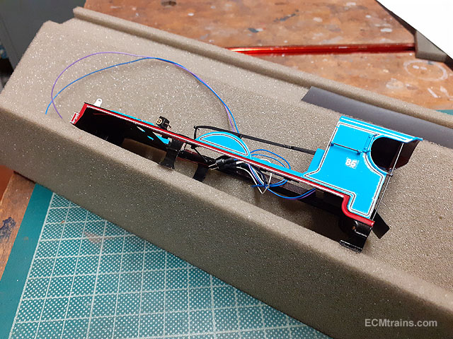
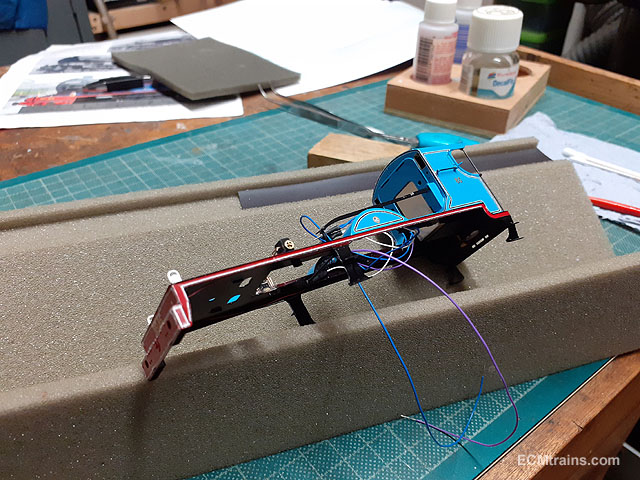
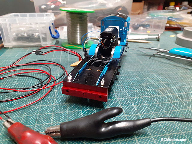
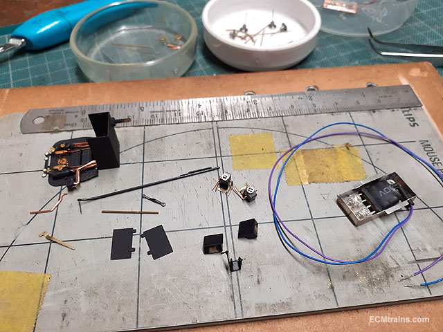
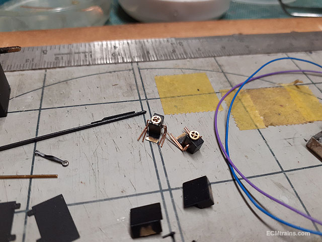
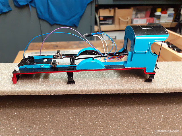
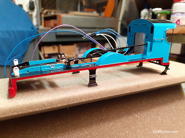
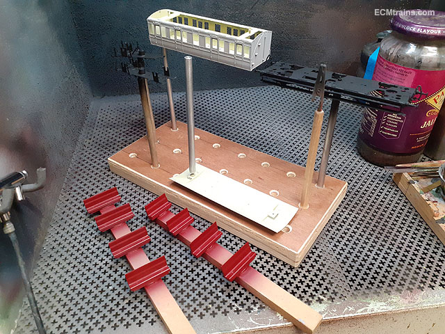
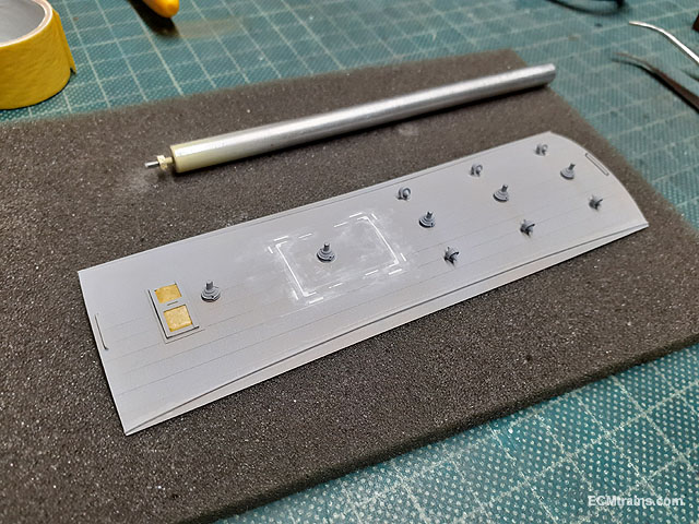
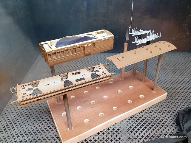
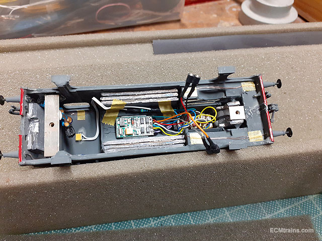
Setting up a wiring loom so that the body can be removed from the loco chassis in the future. With the LEDs epoxied into the lamp bodies its time to glue them to the running plate. Working out the wiring- I'm going to install the LED resistors in the splashers! Lights wired up. Testing. Time to install cab and running plate bits. The oil pumps have .3mm PB wire pipes and hand wheels epoxied on. Regulator handle being acid blackened. Cab handrails too. All epoxied on........ Eoin.
-
A short video of J10 running on the Greystones Layout;- Eoin
- 165 replies
-
- 12
-

-
GSWR/GSR/CIE Six-Wheeled Coaches - ECMbuild in Gauge OO
murrayec replied to murrayec's topic in ECM Model Trains
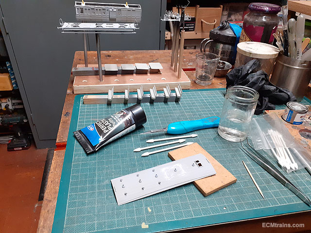
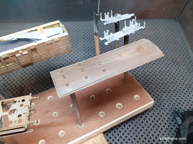
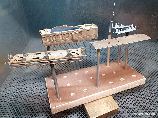
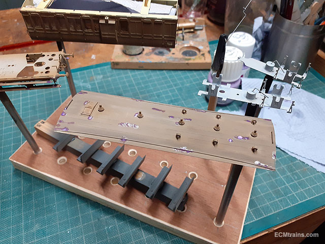
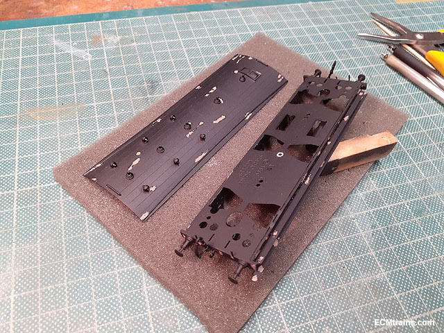
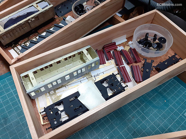
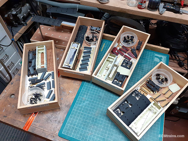
After a small little accident (not going to discuss here) we'r now back on track;- All the kits have had their interiors, partitions, seats, roof, chassis, and bogies painted. Some final filling on the brake/3rd roof where the birdcage was not installed. After the interior was painted cream the roof underside was masked off to paint the topside satin black. The black finish returns around the edge to the underside as the roof has a slight overhang over the body sides! This coach will be the worst kept of the 4 so a light wood brown under coat was used to simulate wood. Some weathering was was applied to give a bit of variation to the wood. Then lumps of maskol were applied to do the paint rip thing on the roof and the chassis. The body will be done later as the green paint is applied. Satin black top coat applied and Maskol removed, more weathering will be done later to complete the buzz. Just about to start the green........ Eoin
- 68 replies
-
- 11
-
-

-
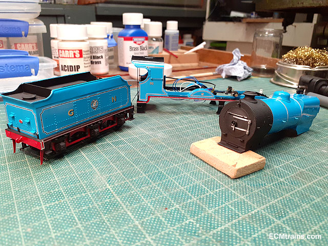
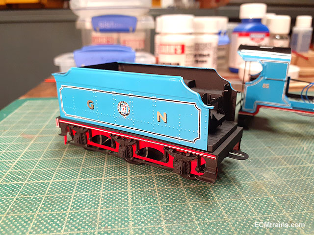
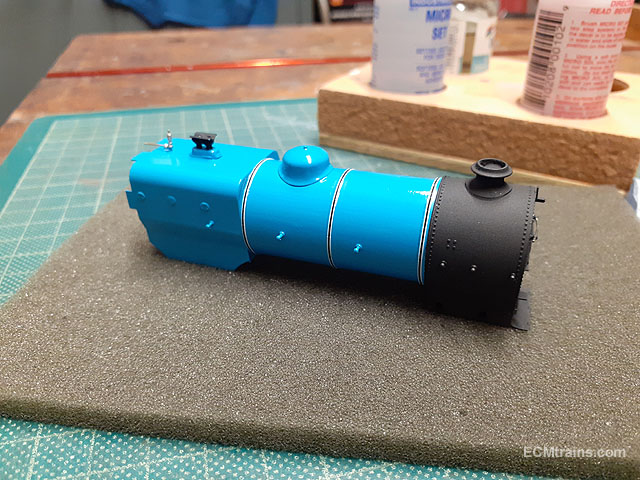
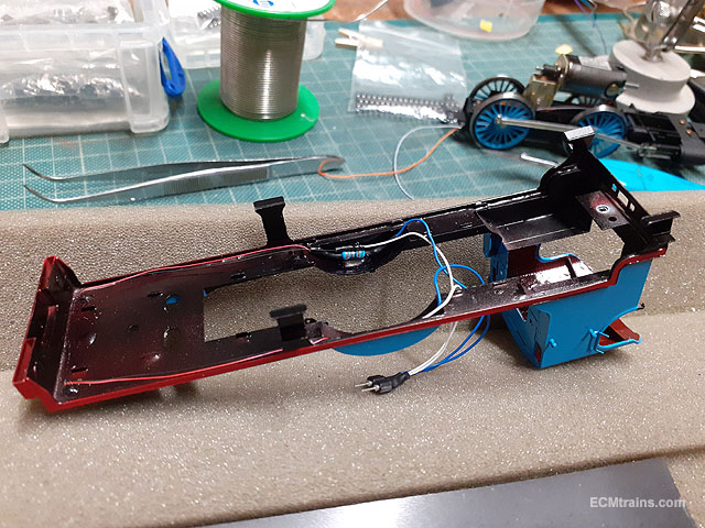
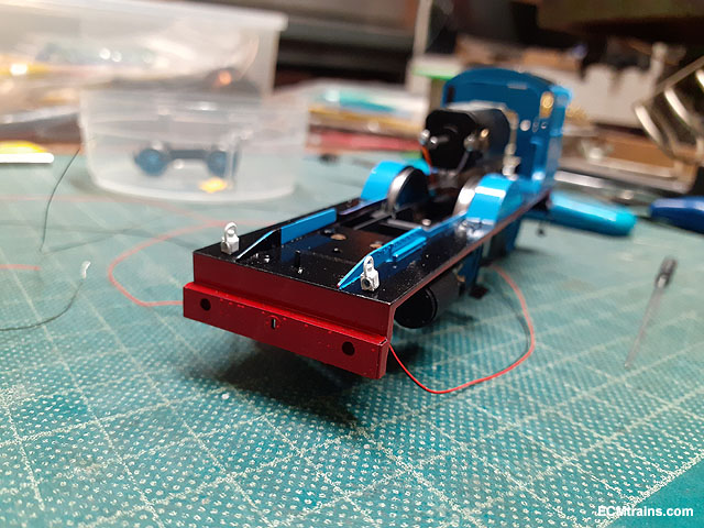
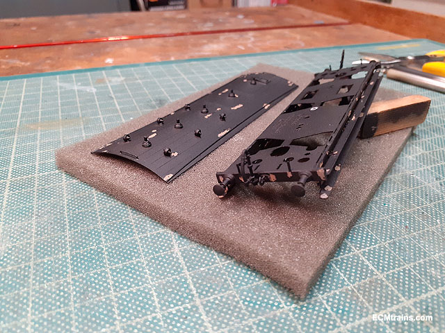
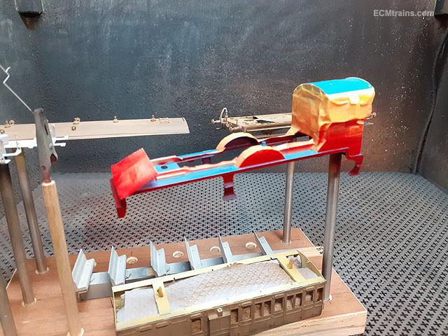
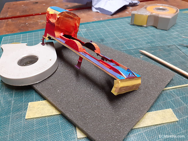
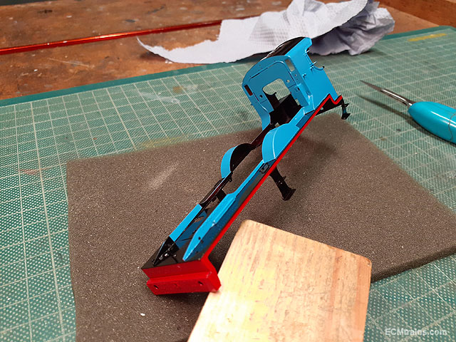
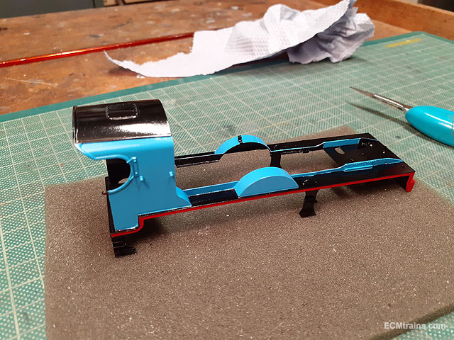
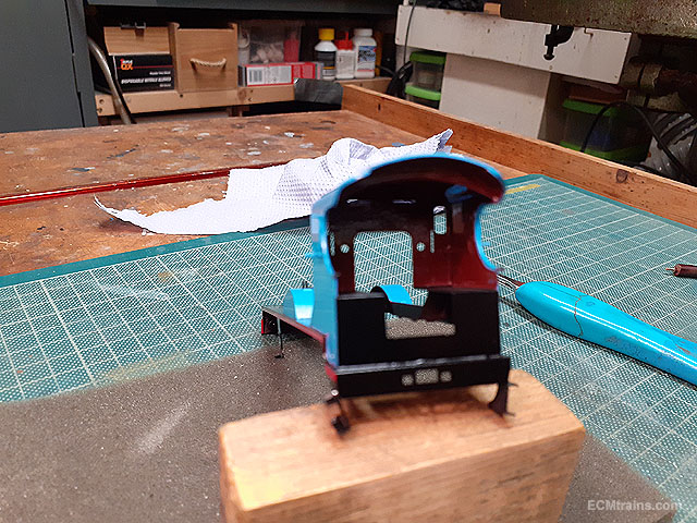
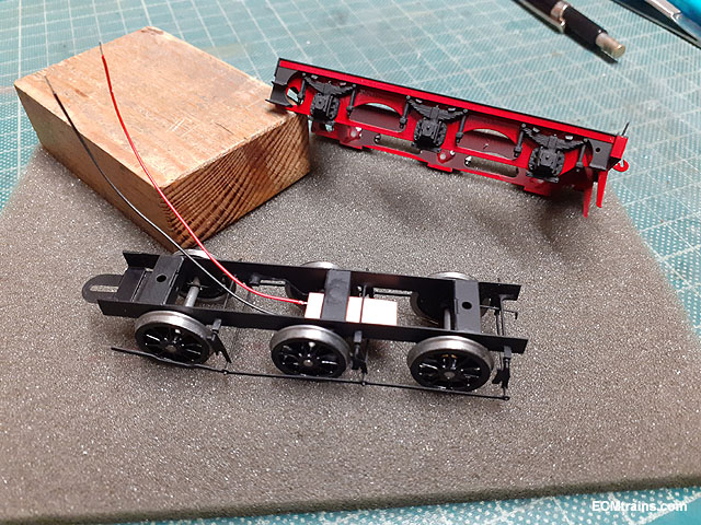
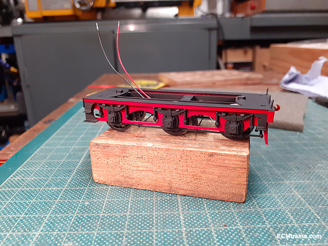
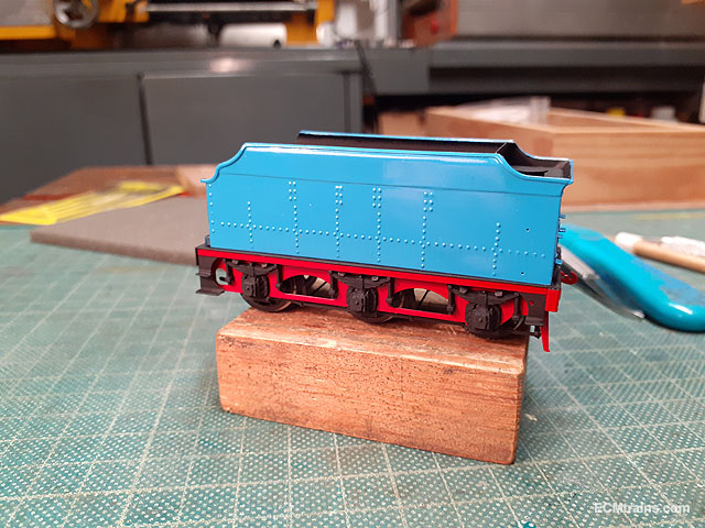
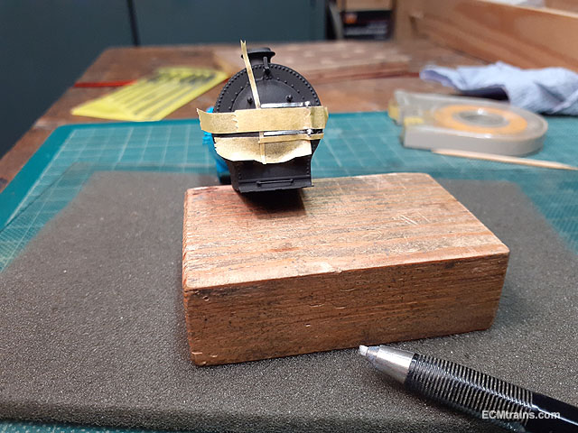
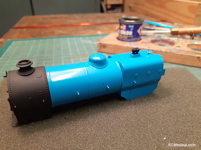
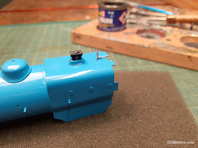
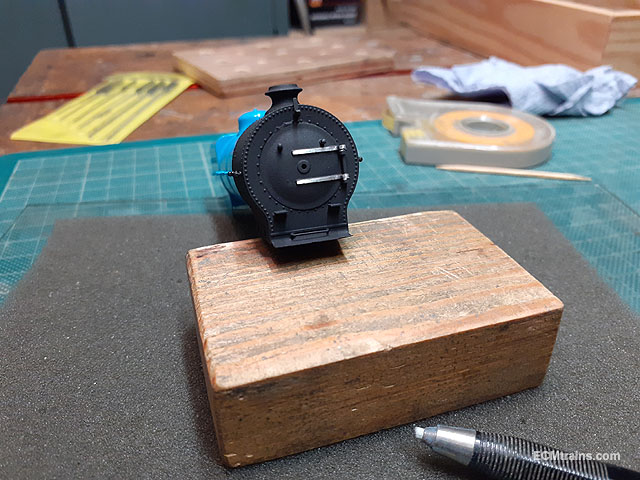
Masked off and painting the read buffer beam & valance. Masking off the red and blue to paint the cab roof, the running plate, and the underside satin black. Black done. Cab painting complete- out of focus! The tender chassis assembled with electrical pick-up installed and the outer frames have the springs epoxied on. Looking good. Smoke box door straps masked off while removing paint from the straps with a fibre brush. Done. Safety valves and steam deflector are painted black. And the whistle had the blue paint removed back to brass. Eoin
-
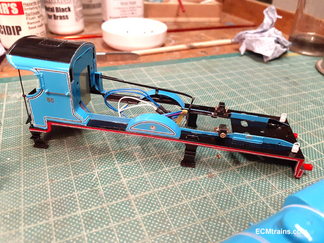
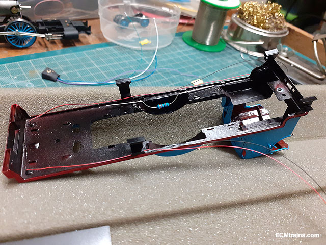
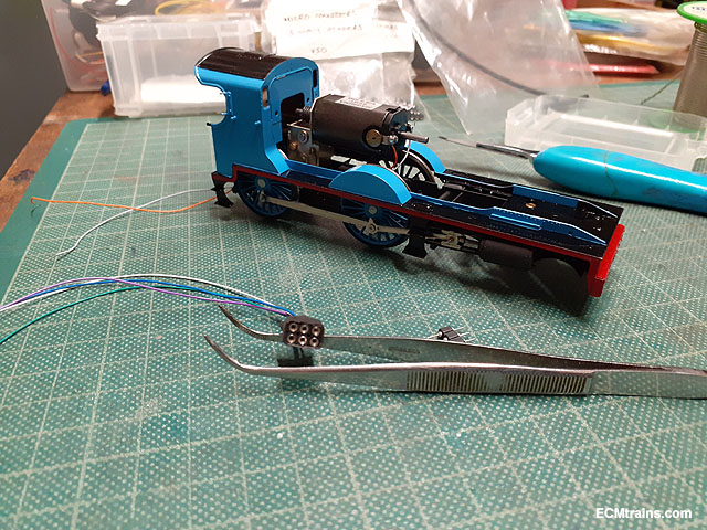
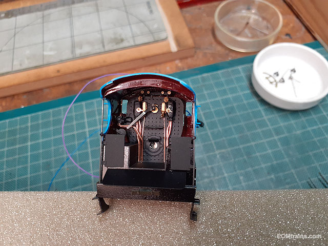
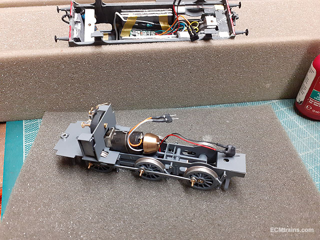
I eventually came up with a plan for the chip location, as seen above. The body can be disconnected from the chassis by mini connectors if needed. With the body on and those crank-pins trimmed it ran fine on the test track. This completes the chassis build- eventually! I will take some video on it's home layout and post it up here when done Complete! Eoin