murrayec
-
Posts
2,775 -
Joined
-
Last visited
-
Days Won
70
Content Type
Profiles
Forums
Events
Gallery
Blogs
Everything posted by murrayec
-
until
-
ESU DCC & Lokprogrammer has built in smoke control for ESU, generic, and Seuthe smoke generators, which handles when one wants the smoke to happen. Eoin
-
It's kind of Walschaerts' without the Expansion Link and something funny with the Eccentric Rod front connection to the Combination Lever! - I don't know the history of these models but generally they were designed in Germany with assistance by Mr Greenly for the British market, so maybe a German version of Walschaerts' Eoin
-
Yes, that's a good idea, I have one of those motors and will give it a try the next blasting session Eoin.
- 26 replies
-
- 1
-

-
- lathe work
- machines
- (and 1 more)
-
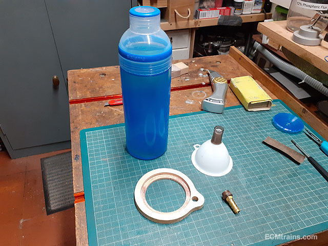
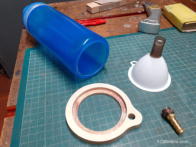
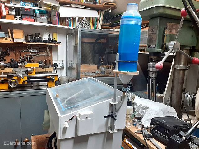
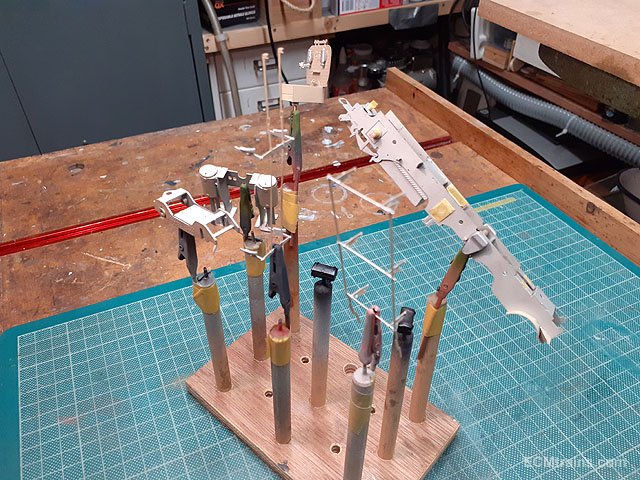
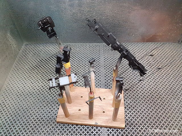
Sand Blaster Hopper Upgrade;- The hopper I made for the blaster (see above), had a problem with supplying a constant stream of sand. This was due to the hopper outlet being done through the bottle lid which caused a backup of sand on the flat ledge of the lid and allied with the small bore of the outlet the sand stopped flowing! So a hopper with a better outlet was required...... A €10.00 water bottle, a small kitchen funnel, a cnc'd ply mounting bracket and a few fittings. This bottle has a lid on top which is better also than the last idea- easier to replenish with sand! The base of the bottle is cut out, the ply bracket is sized to take the funnel and the bottle on the routed ledge, which are both epoxied in to make a seal. A hose clip is used to fix the outlet fitting into the bottom of the funnel with the aid of a short length of 12mm dia hose shoved onto the funnel outlet. Up and running and it works far better, there is still a restriction where the feed pipe goes through the cabinet side! But when one lowers the gun inside the cabinet the sand does flow through. I may make another mod by running the pipe down through the lid, but this requires a mod to the lid and there is not enough time in the day...... These parts took about 30 mins to blast at 60psi, it does take time as the gun is only air brush size, the large blaster would damage stuff like the brake gear and anything delicate on the chassis- note the axle bearings are sealed off so the sand does not get in there. Eoin.

- 26 replies
-
- 1
-
-
- lathe work
- machines
- (and 1 more)
-
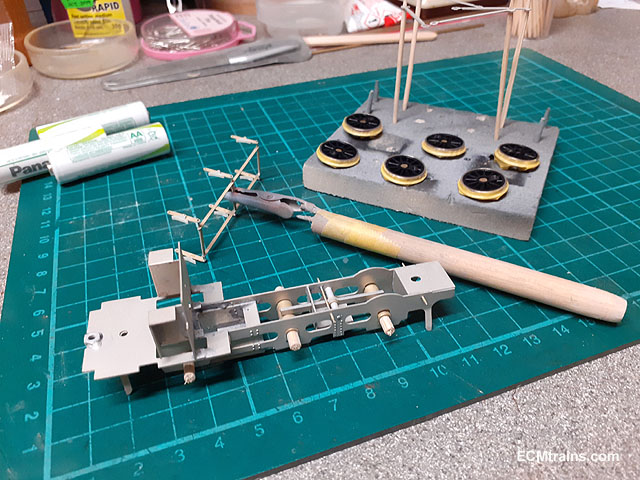
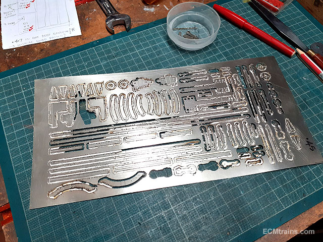
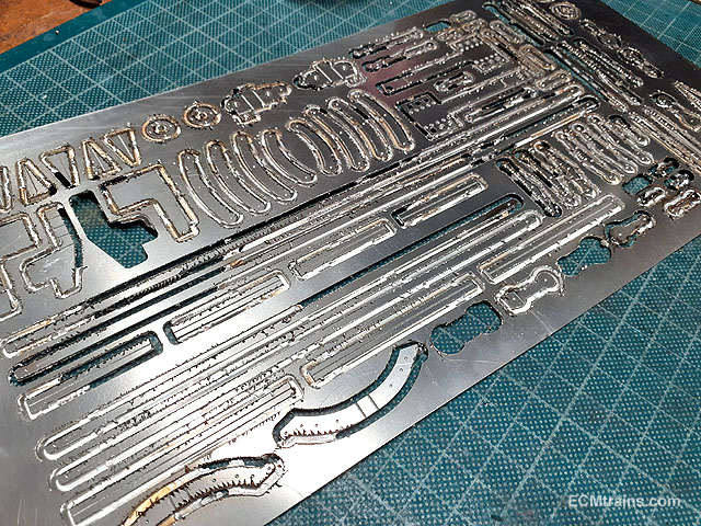
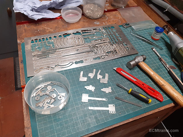
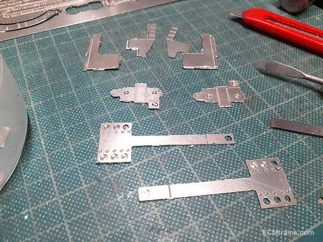
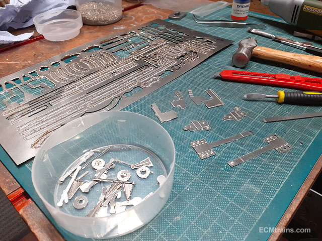
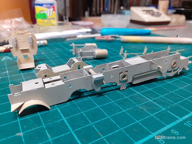
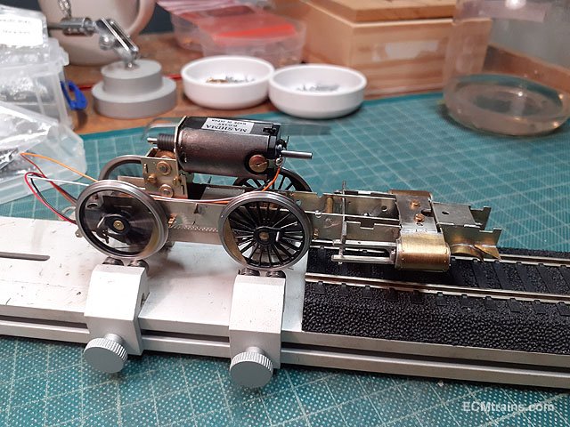
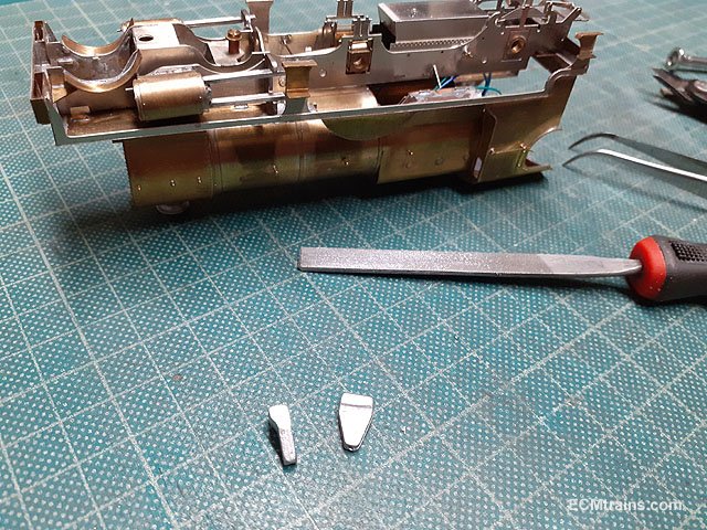
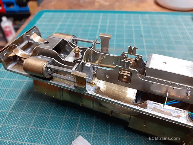
Motion brackets, valve gear and brake gear cutting;- When cutting the parts from .45mm nickel silver sheet, in error I set the cutting passes for wood and not for metal, within a minutes the last 2mm endmill tool I had in stock was dulled. After resetting the cutting passes for metal things progressed poorly, as this was the only tool I had- things had to be left running! Overheating caused the sheet to come unstuck from the machine bed and this caused distortion, intermittent cutting, and a massive burr on the cut edges. Nerve racking time, but the tool and the sheet of parts survived, just a bigger clean up required. Chisels, knives and the mini drill being used to get the parts out. A lot of fettling to do........the joy of modelling!! Eoin.
-
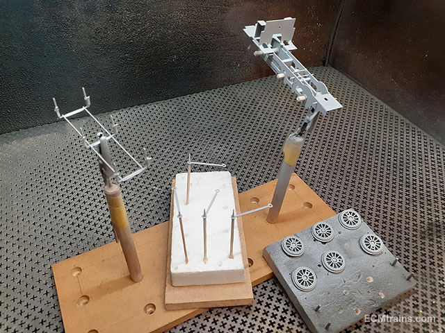
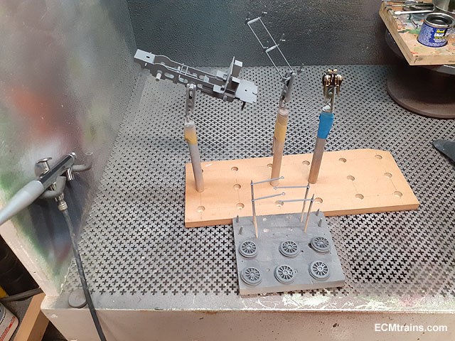
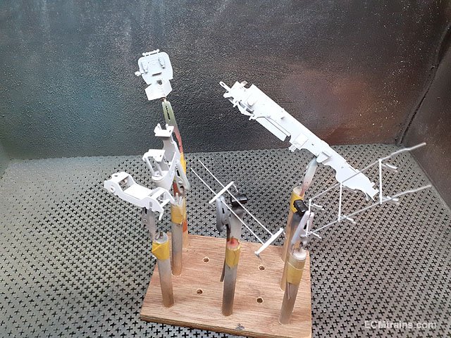
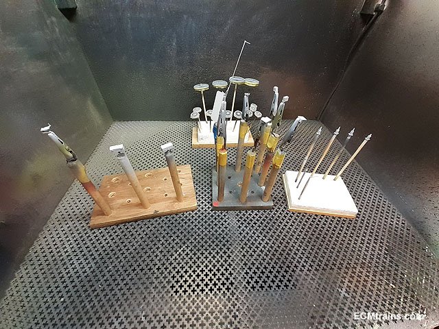
The chassis is eventually painted;- Parts being sandblasted. Everything ready to start a painting. Etch primed & under-coated. Top grey coat & lacquered. The backhead was painted satin black, then the brass fittings were epoxied on and finished with a coat of lacquer. Final assembly to come soon....... Eoin.
- 165 replies
-
- 12
-
-

-
until
-
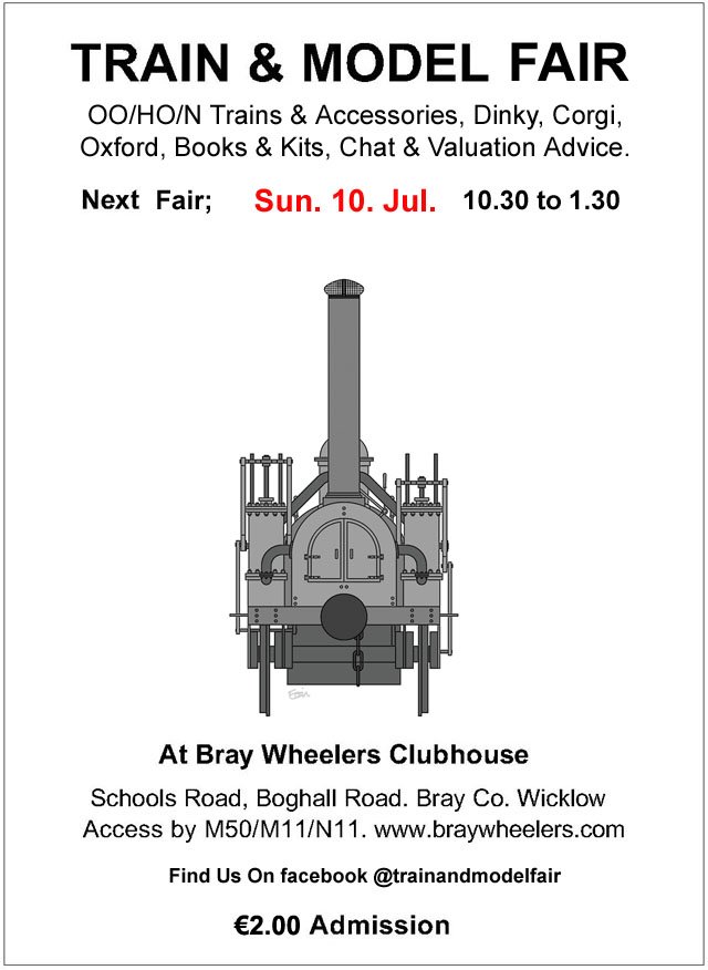
The July Fair Date;-
-
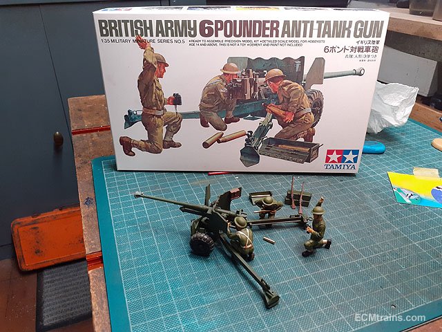
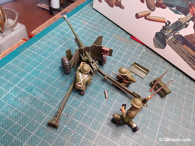
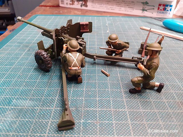
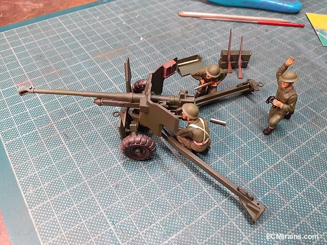
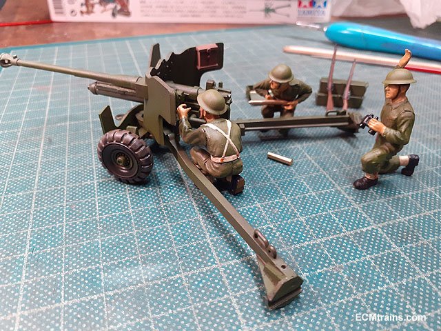
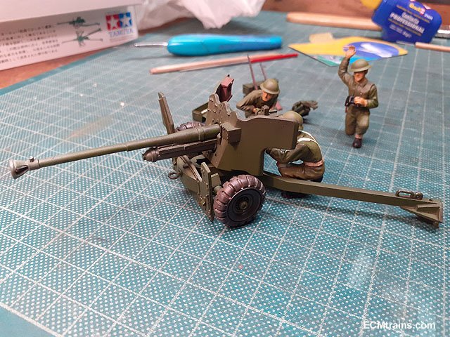
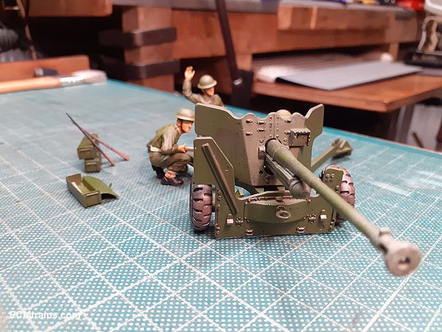
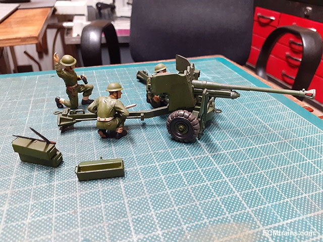
Staying with the artillery theme! Just completed a 1:35 6 Pounder Anti-Tank Gun;- The kits amo boxes really suffered! so I made my own from folded up brass, also I made the amo from 2mm brass rod on the lathe. I need to make a mounting plinth with some detail and a perspex cover......... Eoin
- 347 replies
-
- 12
-
-
-
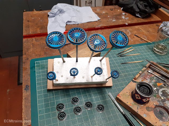
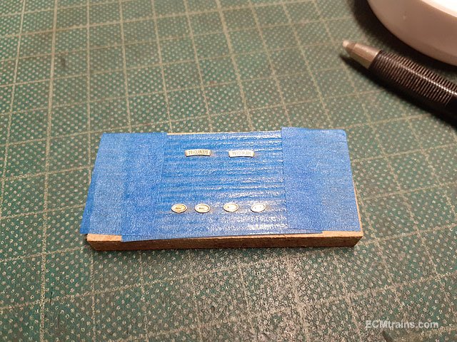
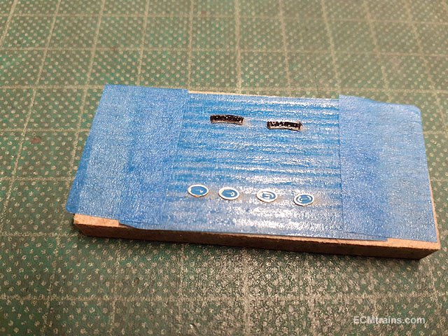
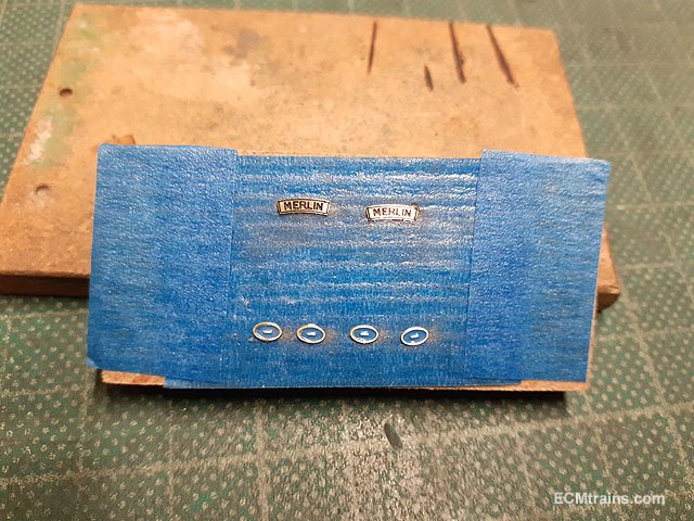
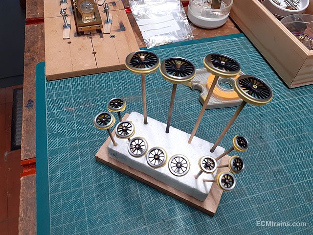
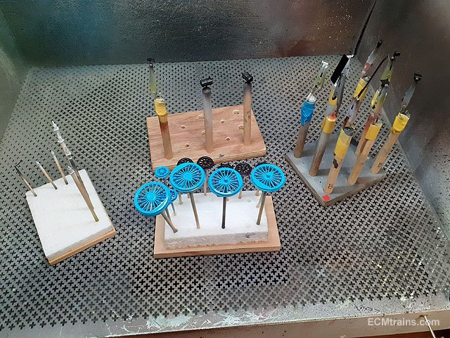
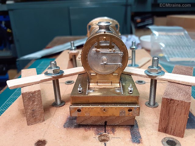
Painting continues;- The chassis, cylinders, brake gear and backhead were sandblasted and setup for painting. Etch primed and undercoat. Satin Black. The loco wheel tyres were hand painted satin black before the masking was removed. A bit of off white being dabbed into the gauge faces on the backhead. The Merlin name plates and manufactures plates are mounted on upside down masking tape for painting. Painted. Then sanded down with wet n dry paper with plenty of water, now ready for a bit of lacquer. The backhead with water gauges, pipework and hand-wheels epoxied on, now just needs the regulator handle stuck on and then its also ready for a coat of lacquer. Eoin.
-
-
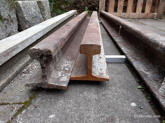
No, that's the first thing I checked. When they were holding up the roof I wondered if they were from the Bray & Enniskerry line!! Wouldn't that have been a find, but alas their to modern I reckon.... Eoin
-
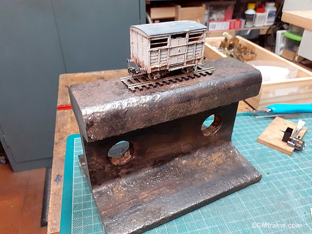
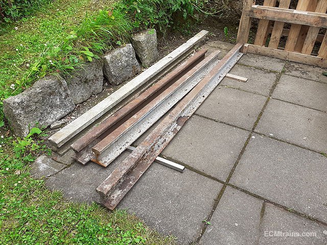
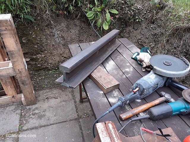
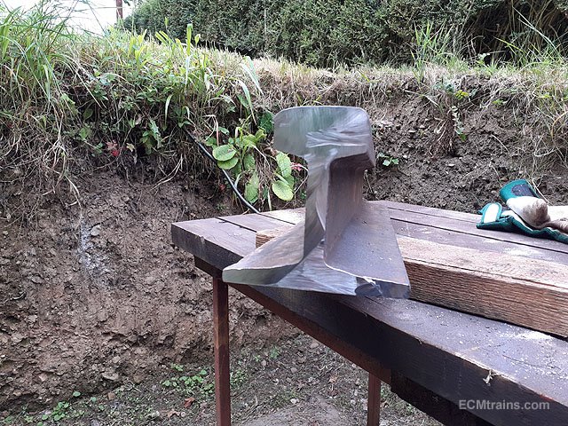
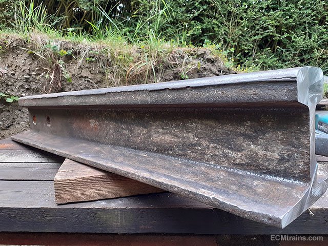
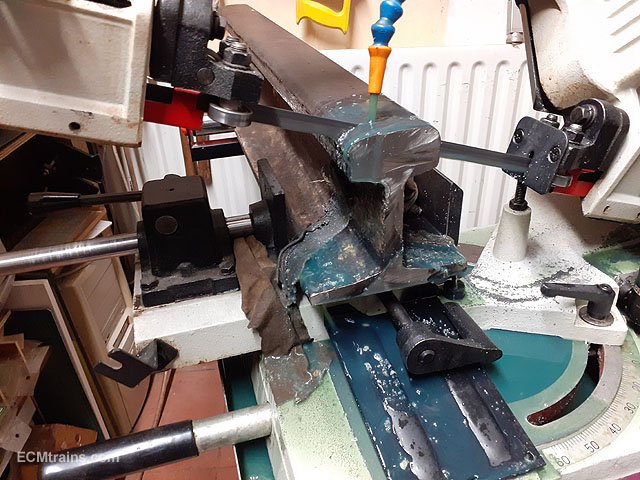
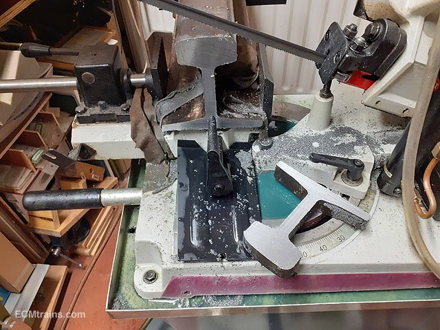
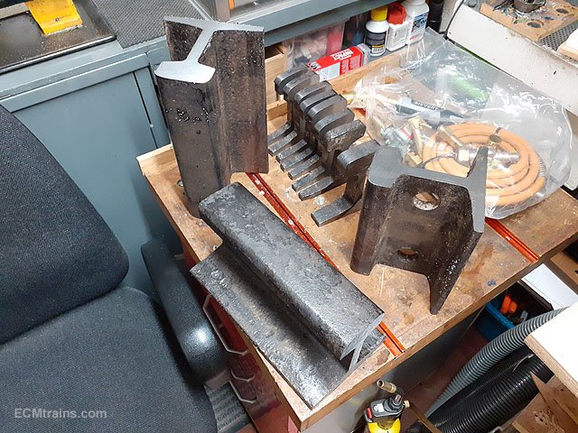
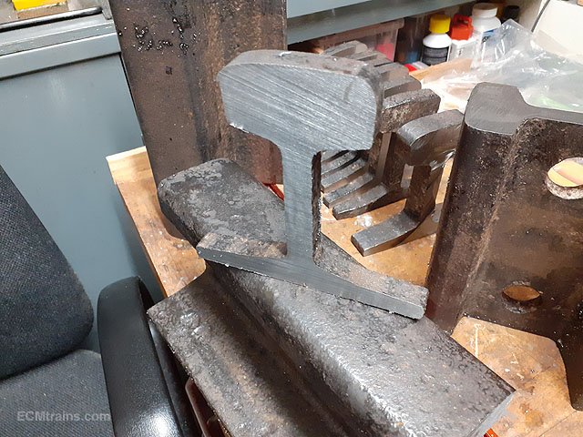
Many years ago while in my neighbours garage I noticed the roof was held up by railway track beams! The house is now being demolished for re-development and I scrounged one of the rails....... After chopping the rail into 3 pieces on the site, a bit of heavy lifting got them into my back garden. Out with the big grinder to chop some into manageable bits. This photo shows a bit of ware n tear on the top edge- so this rail was used. Onto the band saw to cut down to even more manageable size. The large bits will be fashioned into anvils and the small ones which are cut 15mm thick will be mounted on plaques for hanging on the wall. More to follow when I get a bit more processing done......... Eoin
-
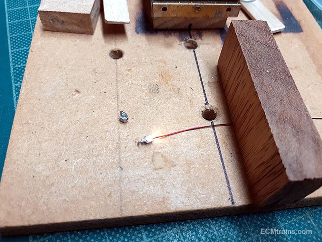
I worked out the front lamp mounting and commenced painting;- The LEDs under test, the lamps will be mounted on the running board using a bit of stripped wire insulation threaded over the LED wires and glued into the lamp base. The lamps will be epoxied on when painted and assembled. Centre front lamp bracket soldered on and this photos shows the drilled holes for the LED lamps. Steam dome and safety valves were epoxied on, the whistle assembly was soldered onto the firebox with the steam pipe dry fitted into the cab front, also the safety valve steam deflector plate was epoxied on the valves. Wheel threads masked up for painting. Wheels and small parts etch primed and under-coated. First colour- eventually got to the blue stage!! Eoin.
-
This is what you get from DC Kits;- The rest is up to yourself. Eoin
-
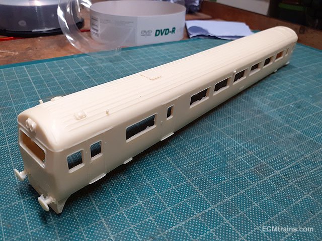
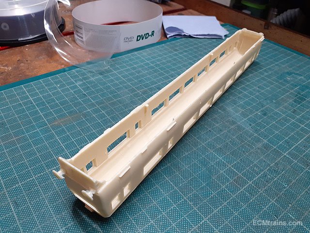
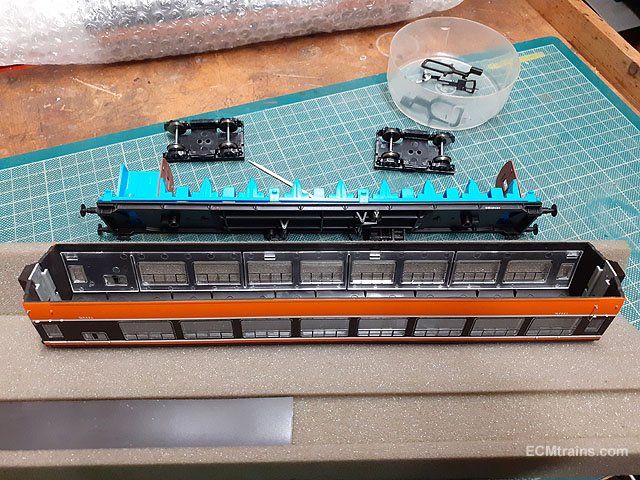
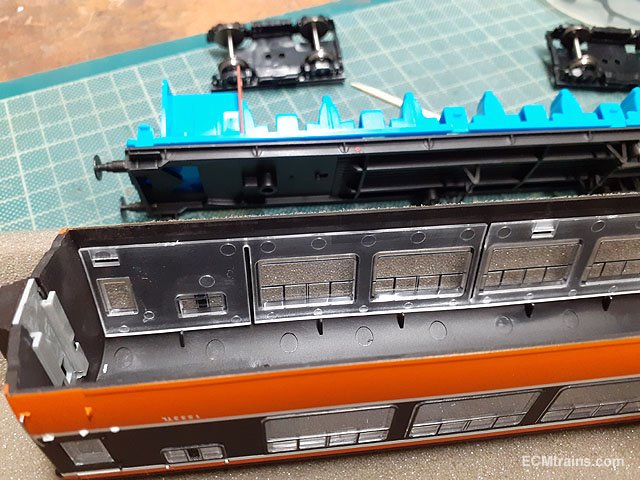
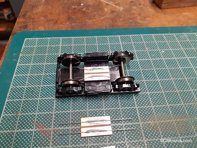
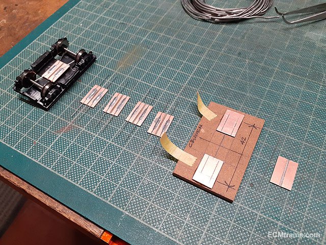
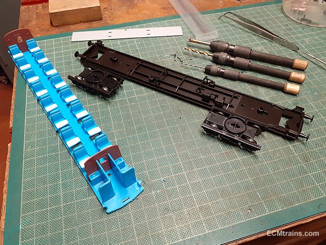
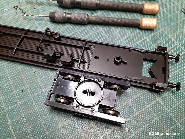
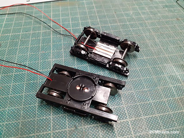
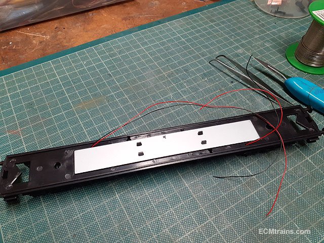
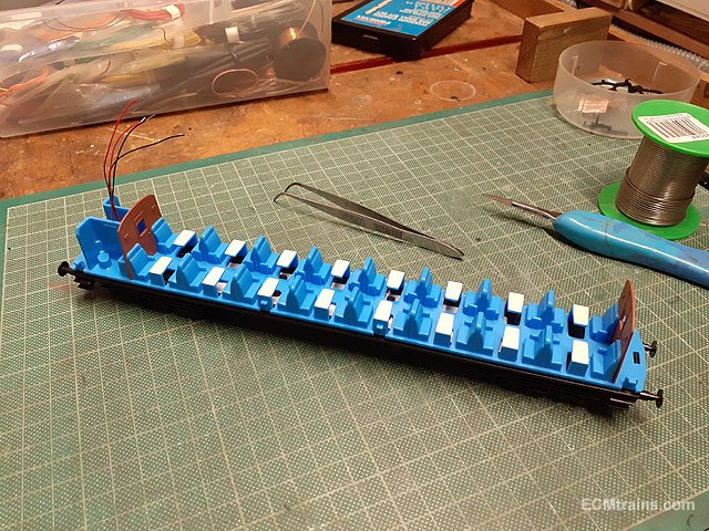
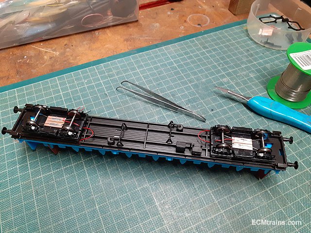
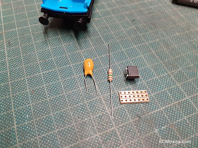
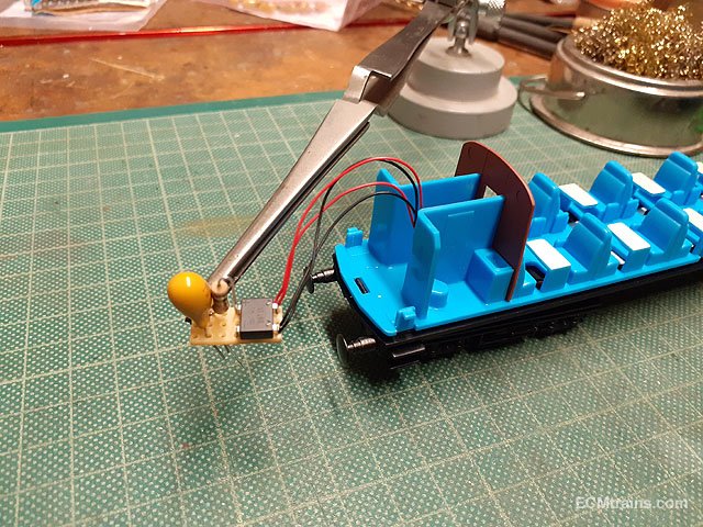
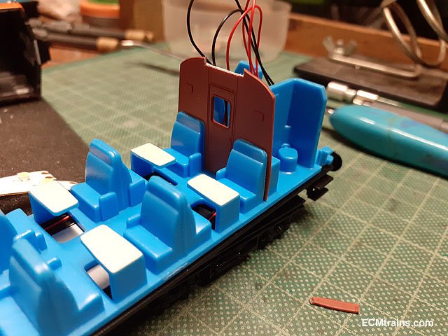
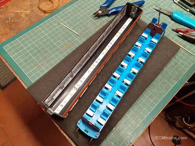
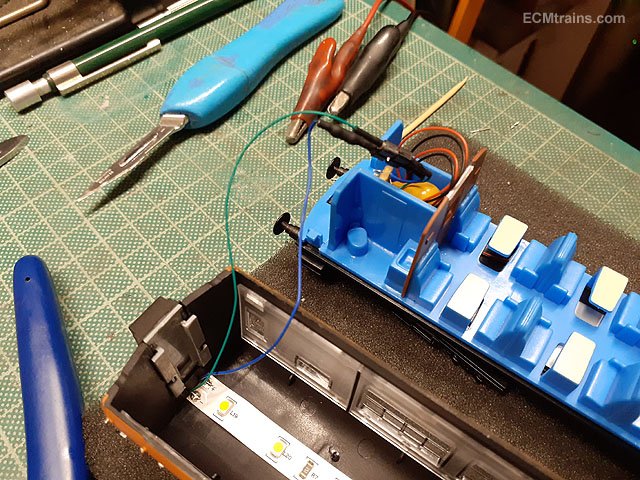
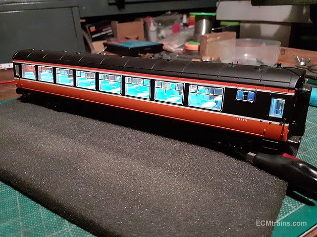
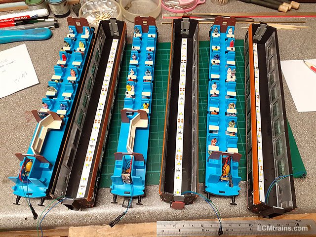
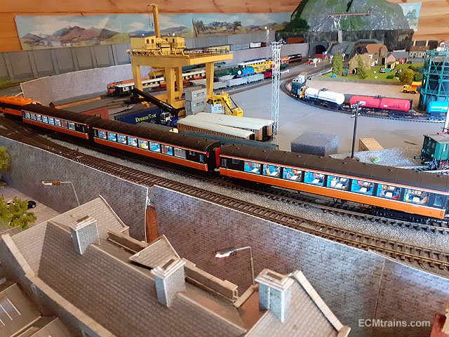
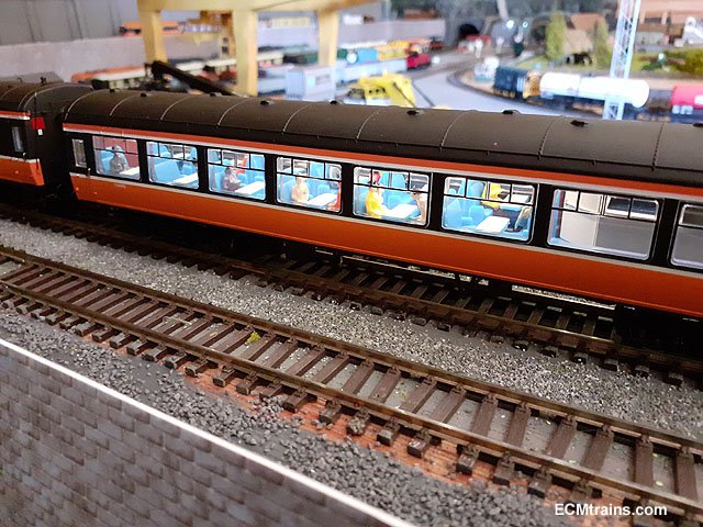
Installing LED strip DC coach lights in Cravens;- The coach body is held on by the floor side dents which slot into the glazing- 4 to each side, use cocktail sticks to disengage the dents and the body lifts off. The bogies pop off by rotating them 90 deg and levering one end up. Setting up the electrical pickup boards which are epoxied to the underside of the bogies, the jig is for soldering the .3mm NS wire to the boards. Holes are drilled in the bogies, the chassis and the floor between the toilets for the wiring. Bogies wired up. Chassis wired up. The wires run along the side of the weight. Floor on and the wiring threaded up through the hole in the floor at the toilets. Wires from the bogies have a generous loop to allow the bogie free rotation, before running up through the chassis. The electronics- stay alive capacitor, a resistor to bring down the LED strip brightness a bit, and a rectifier for polarity control. Electronics assembled. The tops of the coach dividers are trimmed a bit to allow for the LED strip to pass through. LED strip installed. The LED strip has a mini connector to the electronics so that the body can be disconnected. Testing. With lights installed one needs a few passengers! Eoin.
-
I use a 'Ceta Form' stripper from 'Electrical Merchants' if you have one of these outlets close by, it cost €16.00 approx. Here is a link to the type but this is a CK tool and a bit more expensive;- https://ie.farnell.com/ck-tools/431012/stripping-plier-vde-160mm/dp/1283264 Eoin
-
I reckon this would be the best starting point;- https://www.dckits-devideos.co.uk/index.php?route=product/product&product_id=973&search=mk3+dvt Eoin
-
until
-
The June Fair Date;-
-
Yes, the jig has turned out to be very handy, it was originally made to hold the Worsley Works Class F cab while soldering, it is now used in all model building by changing the central mounting to suit the current job or jobs...... Eoin
-
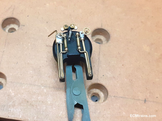
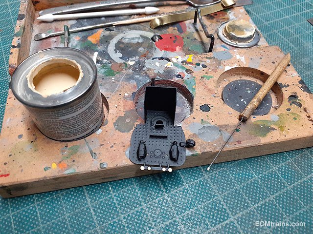
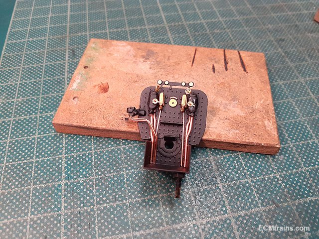
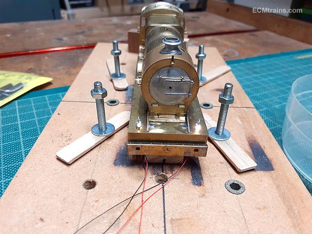
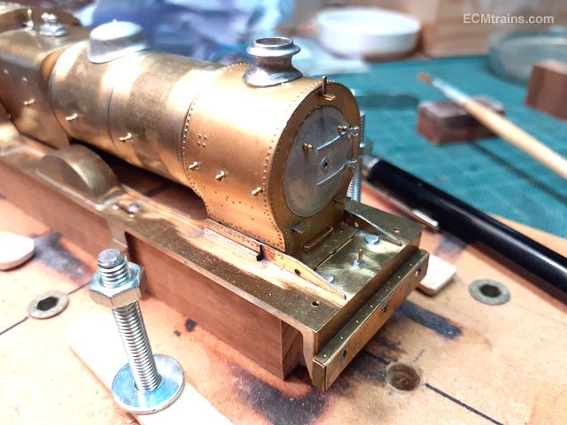
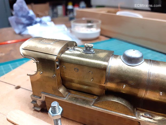
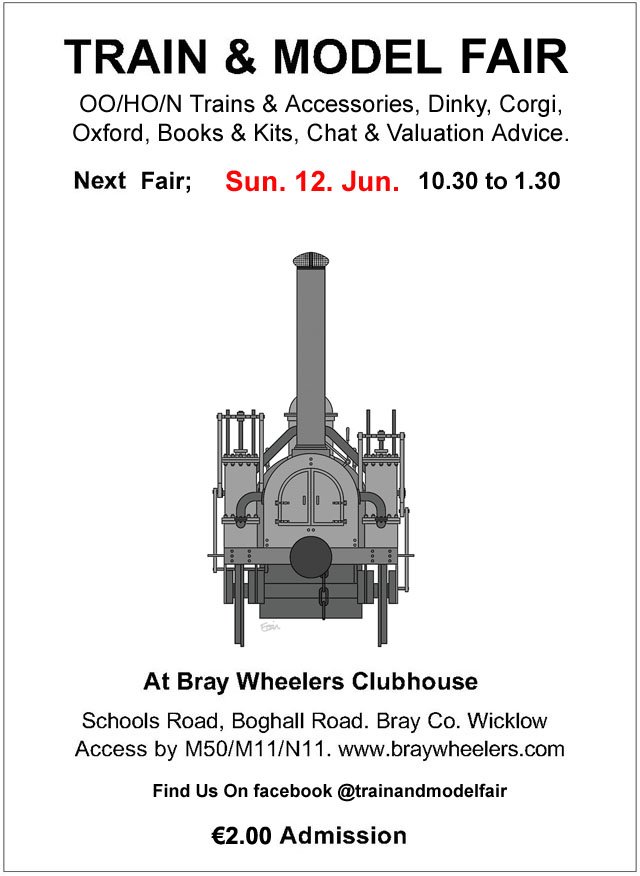
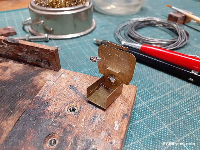
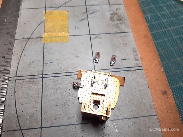
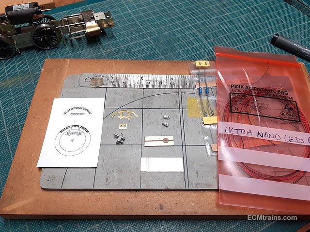
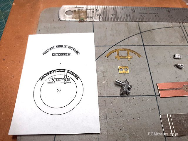
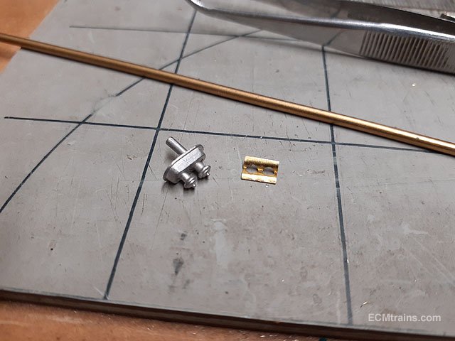
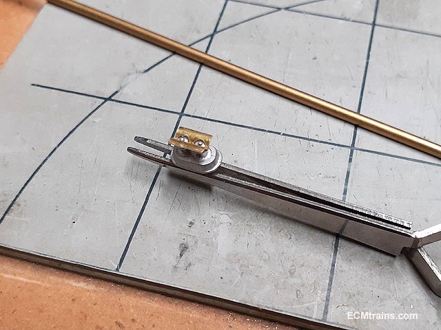
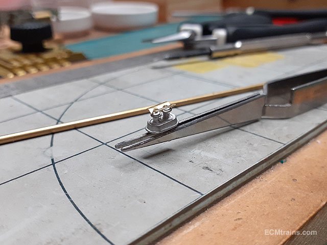
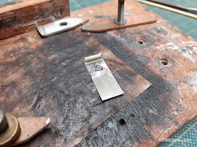
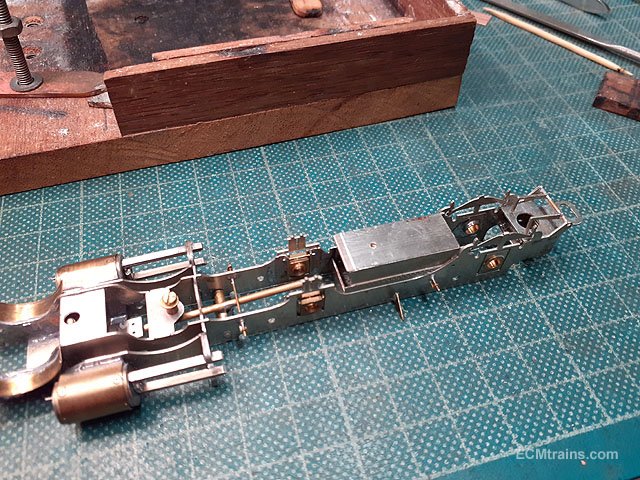
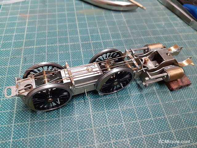
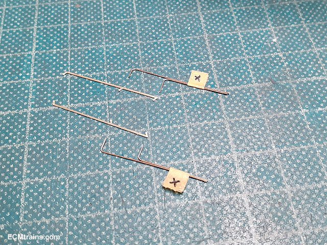
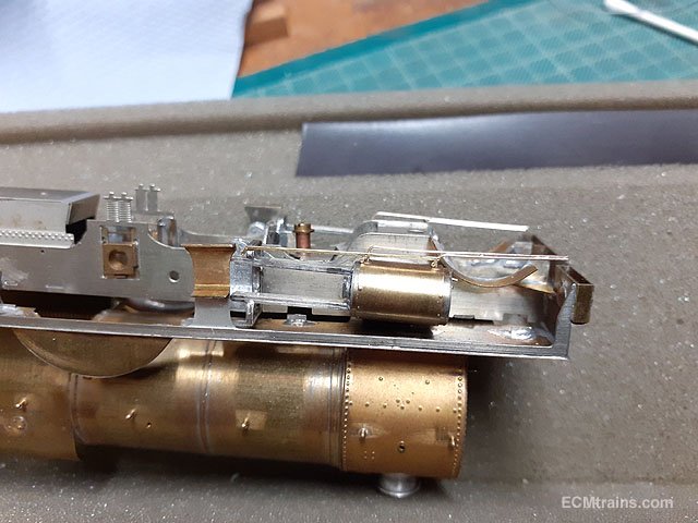
More bits on Merlin;- The vacuum ejector body and bracket soldered to the backhead. The combination injectors being epoxied onto the backhead with a bit of .8mm copper wire glued on the back to allow the later pipes to fit in behind! With the injectors glued on the vacuum ejector pipe work is bent n sized in .8 & .6mm copper wire. The backhead is now ready for paint- the first part for painting!! The white nano leds for the head lamps have arrived, the electrical pickup board and ash pan are ready do go on, and the smoke box 'Enterprise' sign was cut out from .25mm brass. Close up of the sign, it's artwork for making the decal, and a safety valve steam deflector was cut from the .25mm brass sheet also- so the crew don't get electrocuted by the overhead lines! The deflector folded up over a 2mm brass rod. It will be epoxied onto the safety valve later. Th ash pan folded up and drilled to take a 12BA captive nut to hold the electrical pickup pcb board. The pan was soldered onto the chassis from the inside. The pcb board bolted on and the .3mm NS wire wipers soldered onto the pcb board. Wipers under test- after the motor and pickup board was wired up. It alive!! Next was the front sand boxes, these had to be filed on the side to get them to fit without fouling part of the footplate detail. One can see they just squeeze in front of the weigh shaft bracket on the footplate/running board. And the final bits for the chassis- the cylinder drain cock pipes in .3mm pb wire and actuator brackets. Test fitted after the pipes were soldered together and the bottom of the cylinders drilled out, these parts will go on after painting. The chassis is now complete and ready for painting. Testing the fit of the smokebox sign which hangs on the top lamp bracket and has tabs that go in behind the smokebox door rail, also working out the lamp fixing........?? .......testing the new leds, which are white and no electrical shorts on the lamp bodies. Just a few more fittings to go onto the loco body and it will be ready for painting........ Eoin.
-
until
-
The date for next month's Fair = May 15, 2022;-