murrayec
-
Posts
2,775 -
Joined
-
Last visited
-
Days Won
70
Content Type
Profiles
Forums
Events
Gallery
Blogs
Everything posted by murrayec
-
 KMCE has scratch built the armoured tank loco and the full train in 4mm 21mm gauge;- https://irishrailwaymodeller.com/topic/7108-kmces-workbench/page/3/#elControls_125194_menu One could be lucky to see this in the real if he comes to the Train & Model fair tomorrow?? Eoin
 -
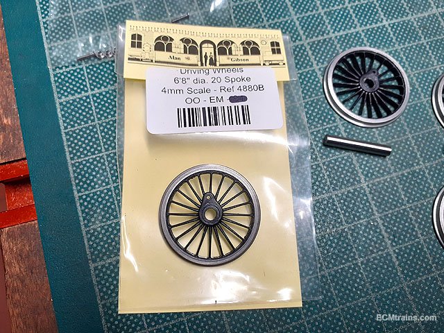
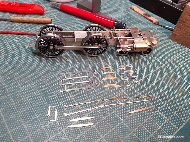
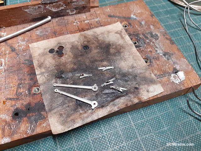
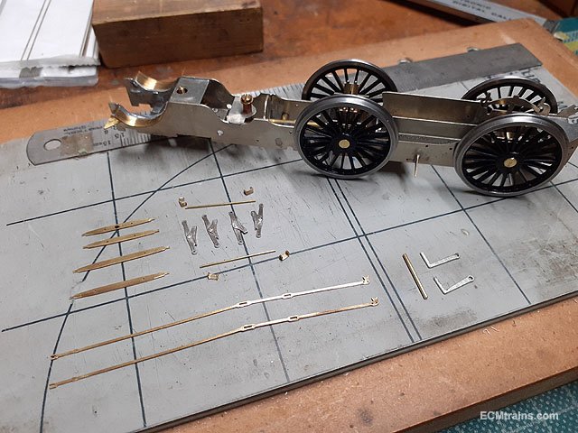
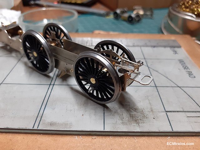
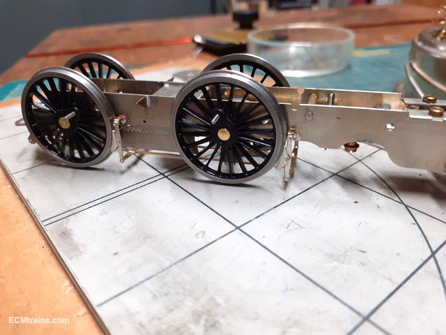
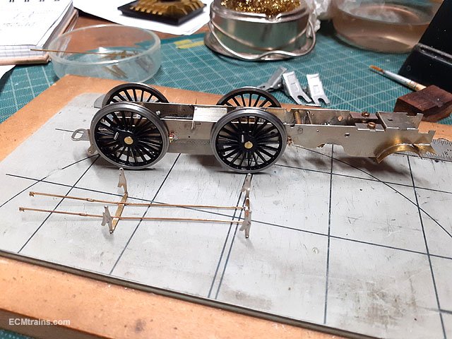
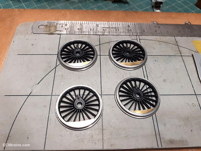
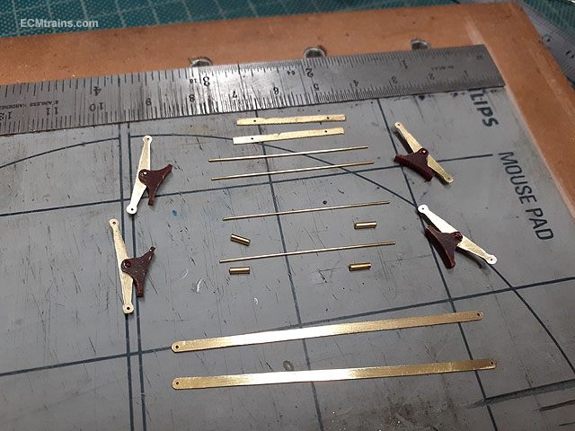
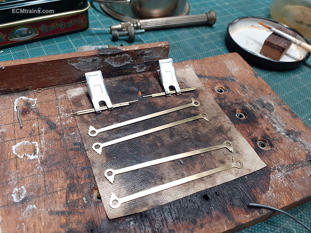
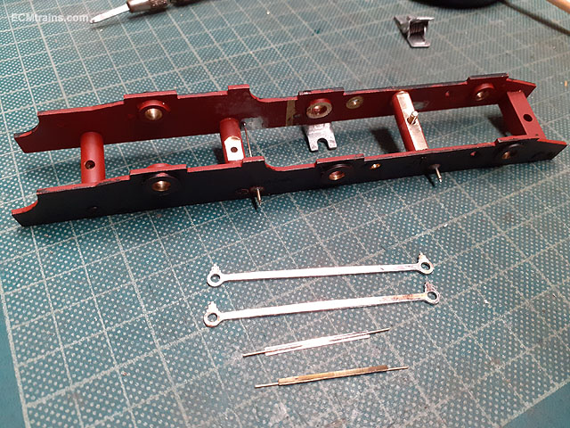
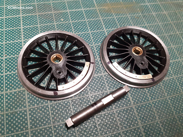
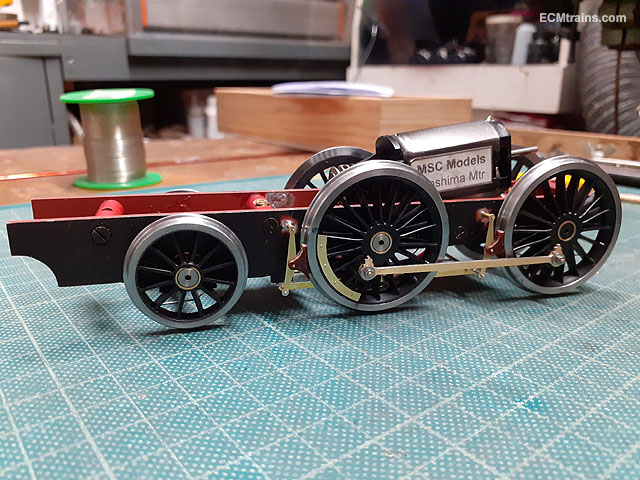
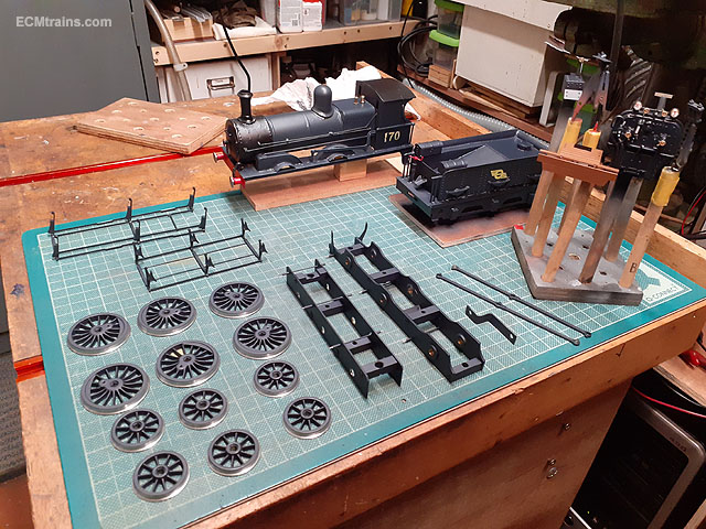
After getting the replacement wheels I decided to finish off the chassis bits before doing the gearbox & motor! The right wheels this time, I got them from Alan Gibson in the end- after weeks of telephoning and just getting the answering machine..... The crankpin BA screws were installed, all was assembled and wheels quartered to broach the coupling rods for free running. In the foreground is the brake parts, connecting rods & wheel weights all cleaned up, holes sized and ready for folding/soldering. Connecting rods and brake shoes folded/soldered, yet to be cleaned up. These are the break hanger brackets being folded up. Their threaded onto the .5mm wire pins through the chassis for hanging the brakes off. Now to solder them on to the chassis. The rear brake frame bracket are fitted onto a .9mm brass wire through the chassis brackets, I left the brackets free on the rod to be soldered when the brake pull rods are on for positioning. .5mm wire pins soldered through the chassis frames with the little spacer brackets threaded on and soldered. Next the shoes, pull rods and beams were joy rigged in place and soldered up- very fiddly as one wants no contact between the shoes n wheels which will cause a electrical short. Those rear brackets are now soldered to the .9mm brass pin. The back end of the pull rods and the top of the shoe hangers are not soldered so that the assembly can be removed. And removed. Wheel weights being epoxied on. The connecting rods were cleaned up and the crankpin end generously broached as these will be at quite an angle out to the crosshead. Wheels back on and time to assemble the gear. Assembled. The connecting rods are at a crazy angle, causing binding on the crankpin bearing and the coupling rod, the bearing is not long enough, which also needs a washer and a bit of free space for this angle. I'll make up a bearing to suit. Eoin

-
Not really stuff the traders carry! ask wrennie on this forum he may be able to help!! @WRENNEIRE Eoin
-
1/32 Scale Mountfleet Round Table Minesweeper
murrayec replied to Georgeconna's topic in Aviation & Maritime Modelling
@Georgeconna Patios! - on the 'bright side' their great for all sorts of projects! wood work and metal work which is to messy or to big for in the workshop.... every modeller should have one! I hope that helps? Eoin -
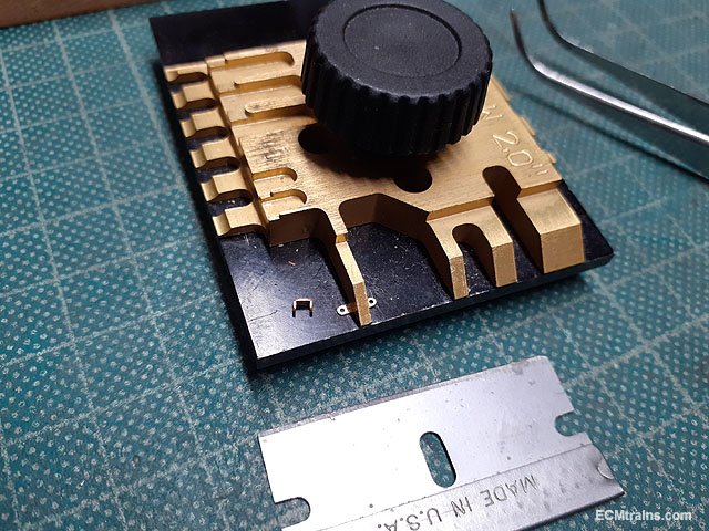
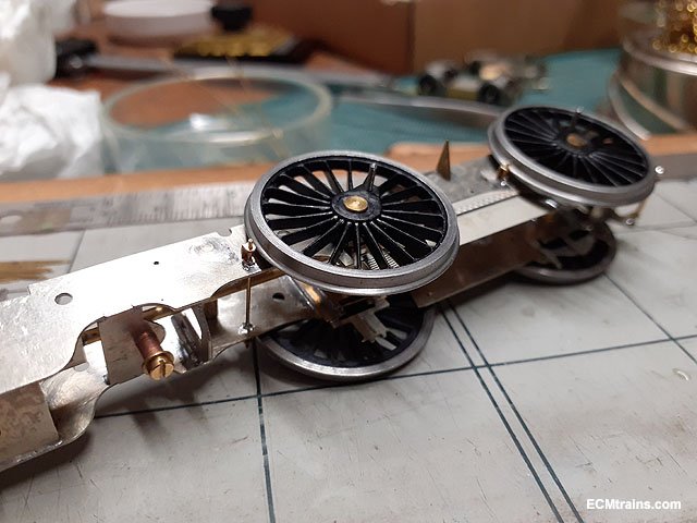
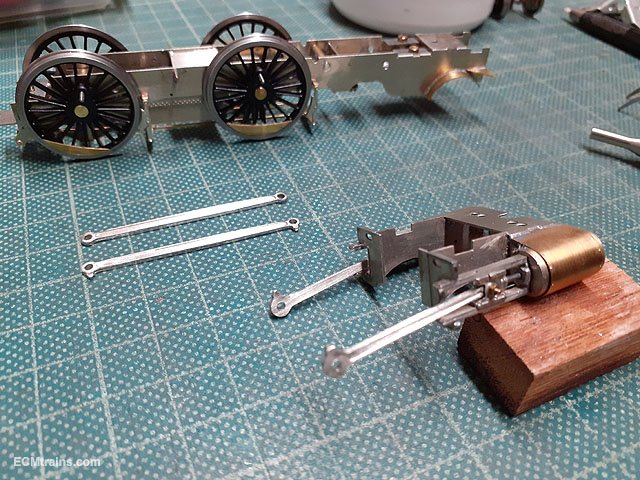
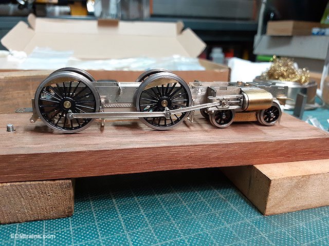
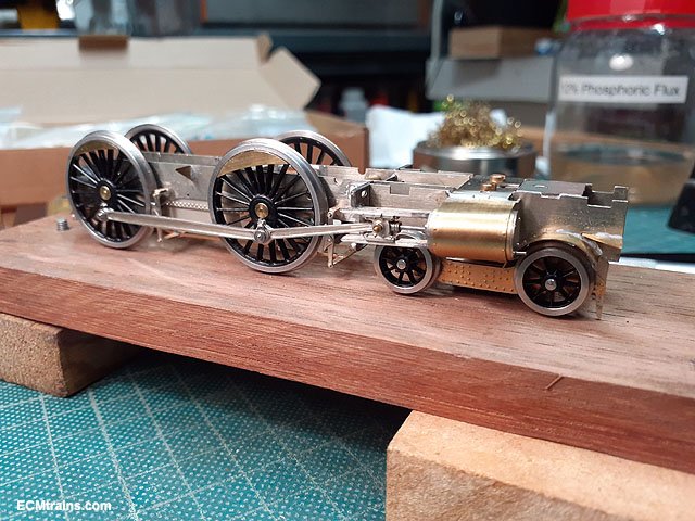
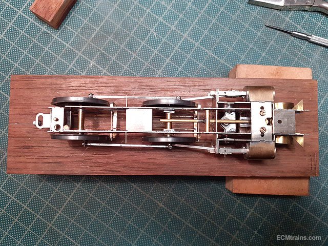
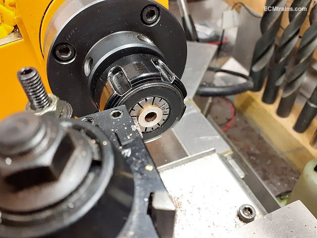
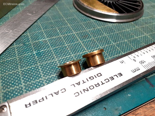
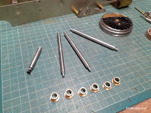
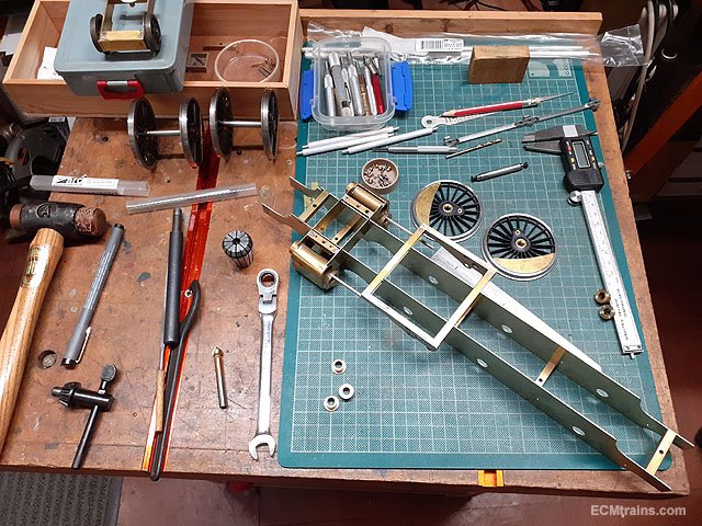
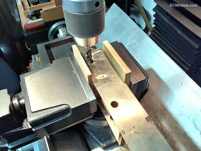
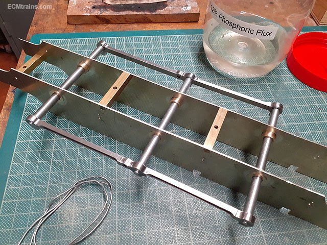
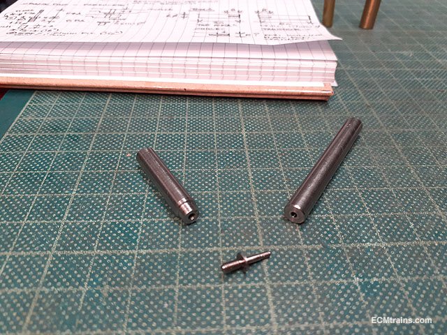
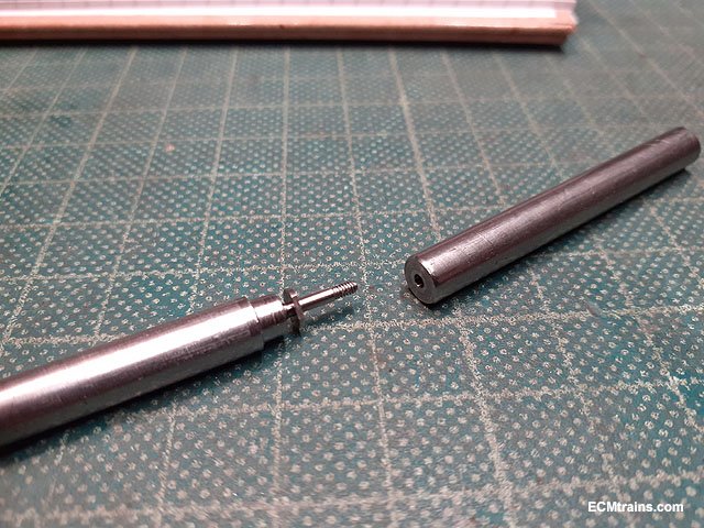
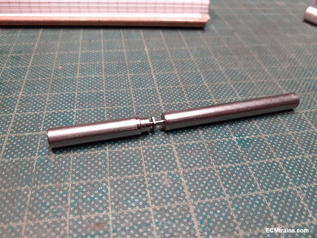
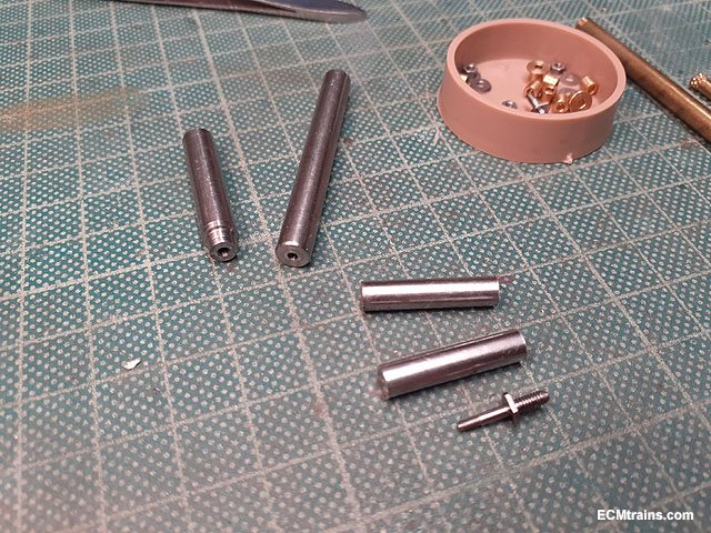
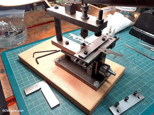
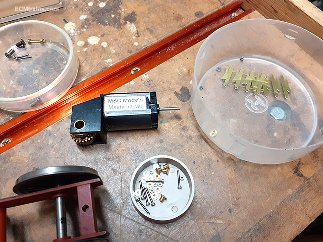
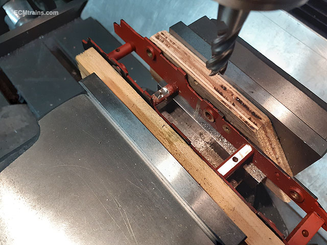
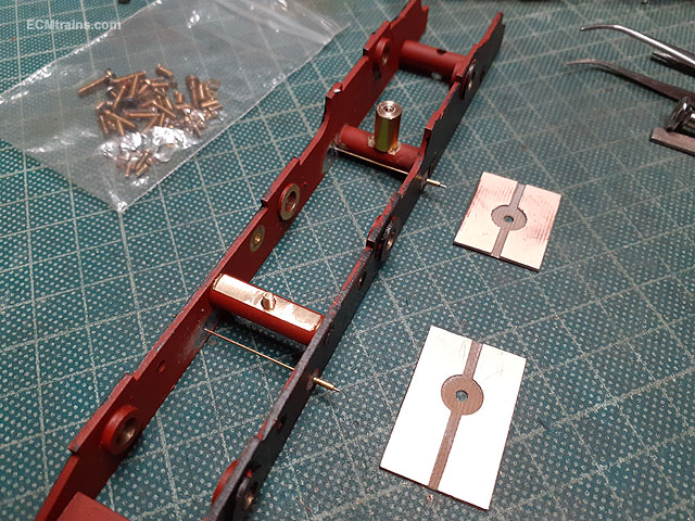
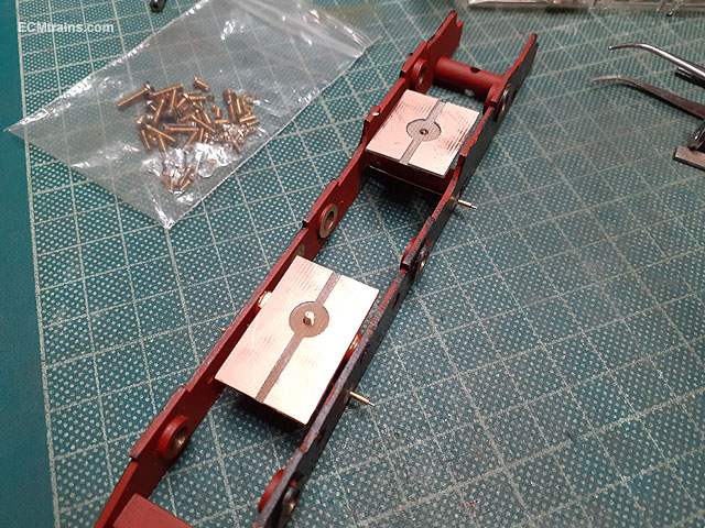
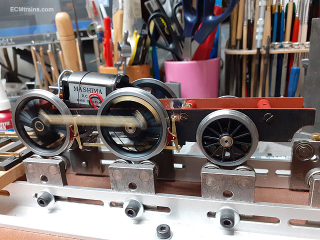
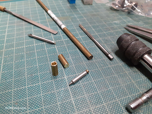
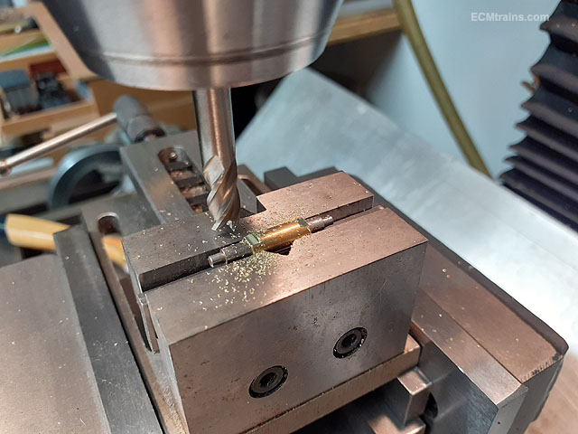
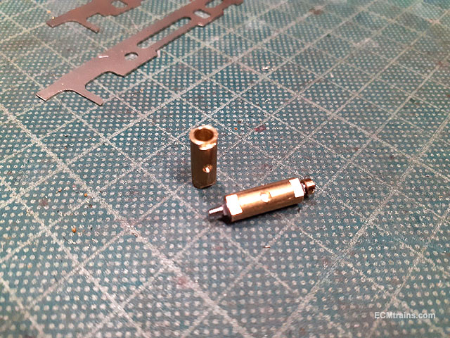
Time to fit the coupling rods and set up the chassis so that final dimensions can be set for the drive rods and crossheads to be made. First though, as mentioned above the chassis is a bit fat and the wheels lock on the axle bearings when bolted up! So a 1mm shaving was taken off the face of all the bearings. Bearings faced and then a set of axle jigs was turned up from 1/8'' aluminium rod to set the bearing centres while soldering them into the frames. Just about ready to solder them in and I noticed the back bearings were sitting a bit low which held the centre wheels about 1.2mm above track level! So a slight adjustment of the frames bearing holes was done on the mill. Adjustments done and the bearings jigged up with the coupling rods, which sat beautifully level for soldering. Next was to set up the centre drive wheel crankpins for the coupling and drive rod thickness at around 15mm- this is longer than what is available! Slaters do extended crankpins which will work for the other wheel setups, but the 800 has huge lumps of metal here and I'm kinda sticking to scale! So some extra long crankpins need to be machined and to do this we need two tools- a chuck tool with an 8BA threaded hole and a tailstock tool to support the end of the crankpin 10BA shank which equates to a bar with a 1.65mm hole in it to be held in the tailstock chuck- on the left is the chuck tool and on the right the tailstock tool machined from 6mm MS bar stock. Demo of the Slaters crankpin screwed into the chuck tool. And now the 10BA shank in the tailstock tool. The 6mm bar stock parts cut to length and ready to be machined, thats a Slaters long crankpin below the bits. Eoin.
-
A few photos of the model just before the crew calls to collect it;- Finished. Eoin
- 21 replies
-
- 14
-

-

-
Impossible to get small size brass drill bits now, and even more impossible to make them yourself under .6mm, it's just to small to focus on even with magnifiers!! Though I did get a book 'Miniature Injectors Inside and Out' by D.A.G. Brown by TEE publishing, in which Mr Brown's last chapter 'Sharpening Small Drill Bits' discusses the difficulty and supplies drawings for a jig to do the job on a diamond lap - I bought the lap but not made the jig yet!! Eoin
-
If one is using HSS drill bits from the 'Microbox' that Expo and craft shops sell - the small bits are as blunt as the chuck end! Expo do replacement drill bits in packs of 10 for the small sizes and these are sharp. The tungsten carbide bits are for high speed drilling and can only be used in pillar drills or CNC machines, as said above hand use is a no, hand use is to slow and snags causing side force will break them, these work best with a 'peck' drilling action only and not constant force drilling. Candle wax- preferably paraffin wax candles is the best lube for all materials, I find. Eoin
-
until
-
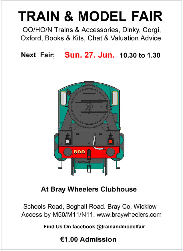
This months Train & Model Fair date;-
-
Walker Diesel Class F - ECMbuild in 4mm for OOn3
murrayec replied to murrayec's topic in Irish Models
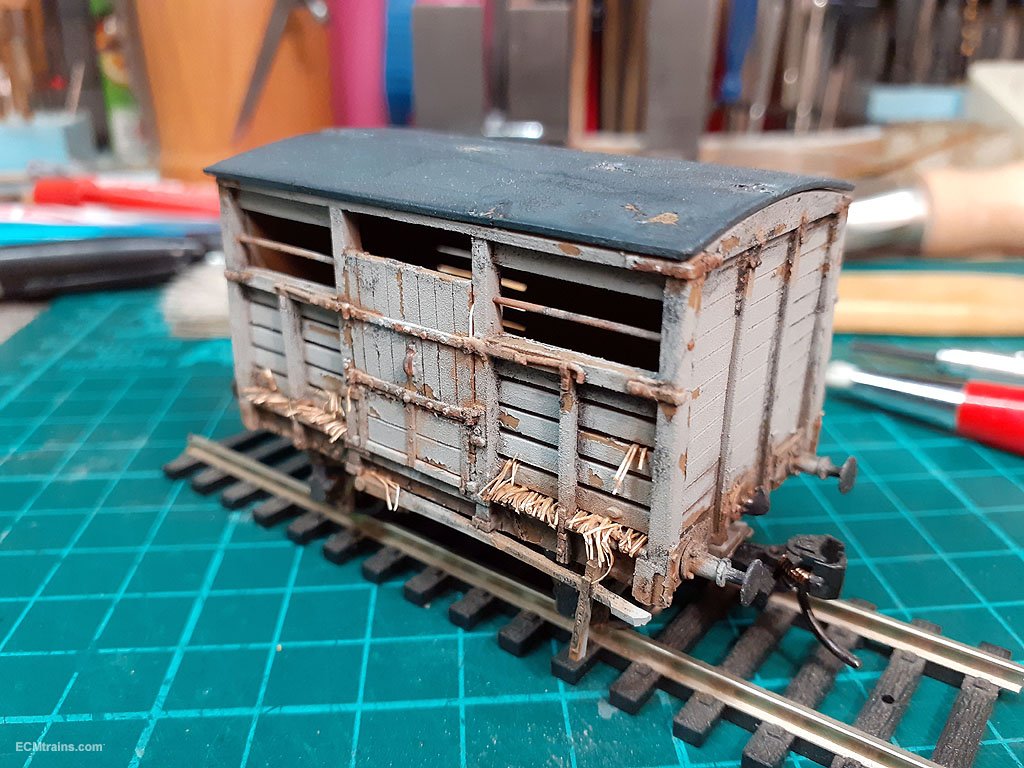
Some weathering done with tips from Martyn's Book and a few of my own..... Eoin
- 136 replies
-
- 9
-
-
-
- class f
- west clare
- (and 1 more)
-
KMCE will be visiting the Fair this Sunday with his fabulous 3D printed wagons as featured on his Workbench thread, don't miss having a look at these...... https://irishrailwaymodeller.com/topic/7108-kmces-workbench/page/5/#elControls_157055_menu Looking forward to seeing these and you all that venture out on Sunday. Eoin
-
Amazing Ken, I cant wait to do my O ones, but will have to as not enough time- I got the printer in March and still haven't used it!! Eoin
-
@declan64 By the special agreement the North is kind of still in the EU, so VAT is charged when selling & buying across the Irish/North border;- https://www.revenue.ie/en/customs-traders-and-agents/brexit/information-for-businesses-trading-with-ni/vat-trade-with-ni-after-transition/index.aspx It's down to ebay to ensure VAT is charged if the seller is not registered for VAT, it's also down to ebay to return the VAT charges to Irish Revenue or do VAT offset in their returns...... Eoin
-
Yes the Guy Williams book is a must have reference for building loco models, as well as Mr Rice's book on building OO chassis and etch kits.... Eoin
-
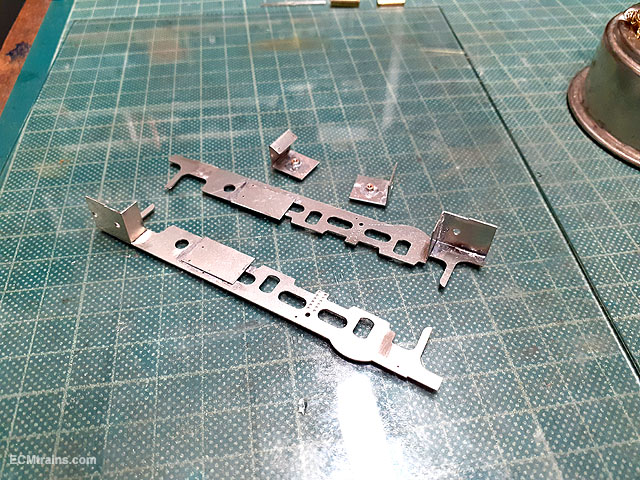
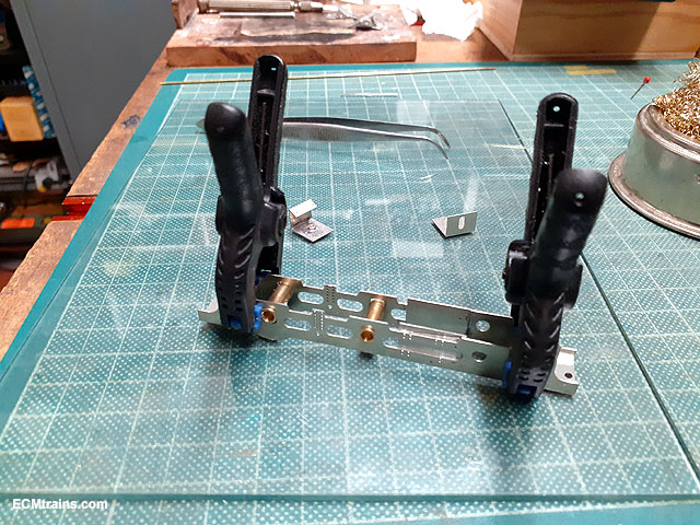
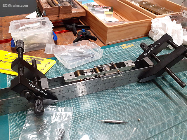
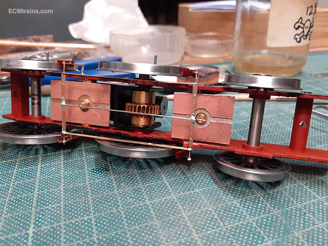
I stuck the chassis together this evening. A bit of riveting to the frames first. The fire box sides have been soldered to the inside of the frames, the frame spacers folded, soldered, and nutted- 12BA nuts to hold the pick-up system on the underside. Also the laminated compensation beam was soldered, two 1.2mm ID aluminium tubes cut, which will be used to centre the beam on the 1.2mm brass pin soldered accross the frames. The back and front frame spacers are soldered onto the alternative frames, these have tab n recess fitting which will keep the frames square.... Frames brought together, squared and clamped. The brass tube wheels bearings are now fitted after checking free movement in the frame slots. Soldered. Checking the fit of the rear axle bearings with an axle jig and the rear connecting rods- it's spot on!! Inserted the compensation beam, brass pin and aluminium tube spacers- aluminium! because the solder wont stick to it when the pin is soldered to the frames which can wick in and solder the beam to the pin- that bit has to rotate. Wheels also on and setting up for motorising...... Eoin.
-
Excellent Ken, And Snap! I have been working up the drawings for the same project in Gauge O..... Eoin
-
until
-
This month's Fair date;-
-
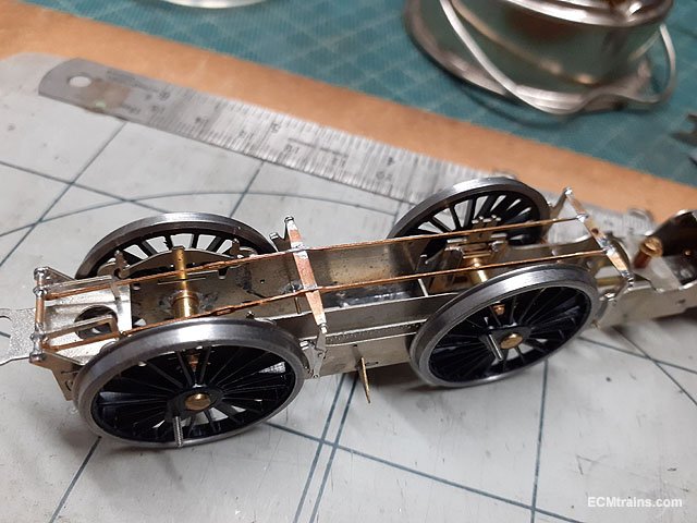
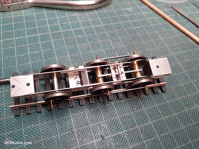
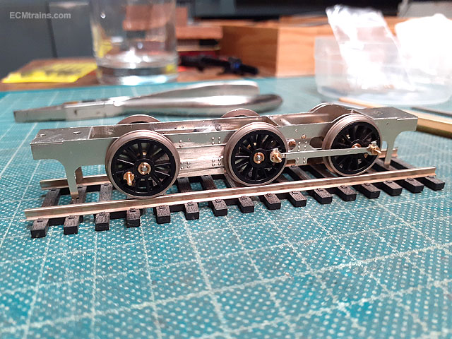
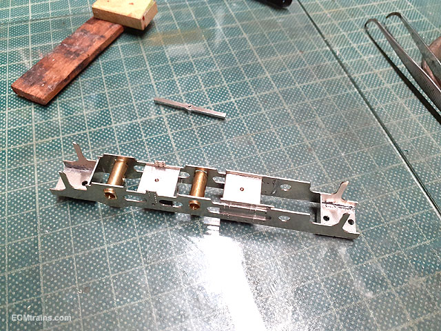
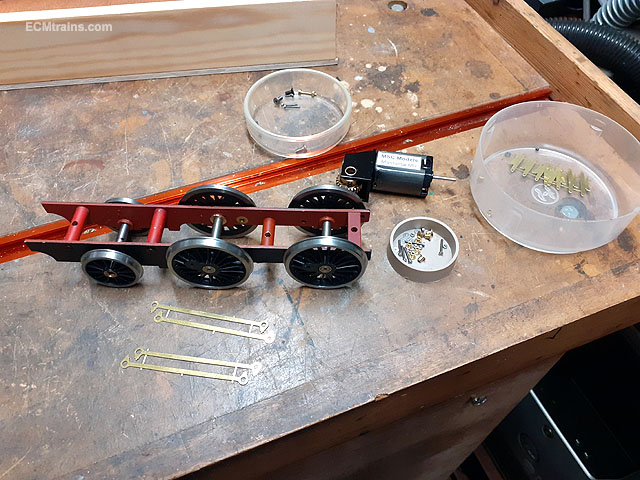
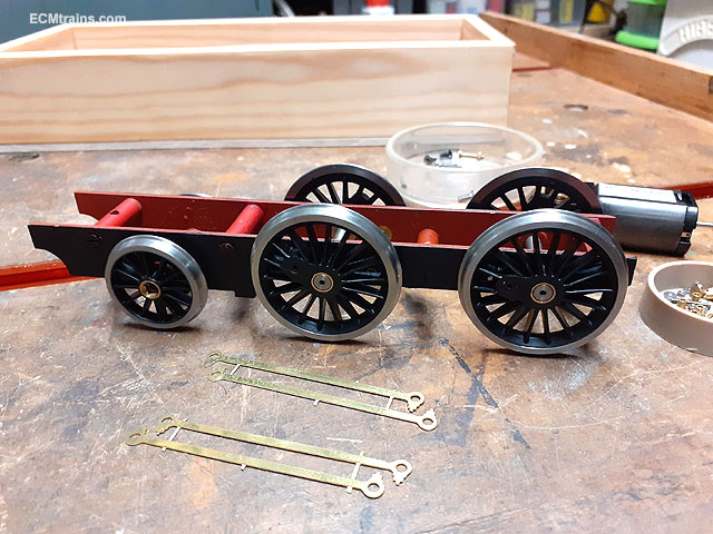
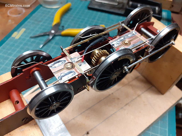
A Class G2 chassis required coupler rods, brakes, wheel weights and electrical pick-ups. On arrival, with brass etched rods and brake shoes- though I'm using my own Tufnol shoes as these insulate the wheels and one can have them right up against the tyres! After a plan of action was worked out the parts were cut- brake hangers/rods and wheel weights from .35mm brass sheet, pcb board was machined for the pick-ups and the Tufnol shoes. Milling flats on the frame spacers to provide a seat for the pick-up boards, the frames were also drilled for the mounting pins which hold the brake shoe hangers. Brake parts almost assembled. Soldering the laminate coupler rods and cross brake rods. Wheel weights epoxied on and a flat was milled on the motor axle to seat the gear wheel grub screw. A 10x6mm dia brass rod downstand was made and bolted to the front frame spacer to provide a seating/fixing for the front axle pick-up board. The pins for the brake hangers were also soldered in. A 4mm long tube is soldered on the pins to hold the hangers in position. Wheels back on, the brake gear was soldered up and the coupler rods fitted. The brakes are removable to access the wheels. .45 NS wire pick-ups were bent up and soldered to the pcb plates and all was wired up to the motor. And finally test running the completed chassis. A few tweaks are still needed on broaching out the coupler rod bearings, but it's ready to go off to it's crew for painting and fitting the body. Eoin
-
Me to! Every so often in the process when things fit one sits back and thinks 'did I really make that' These moments drives one on through the mundane repeat process for the next eureka moment! Eoin
-
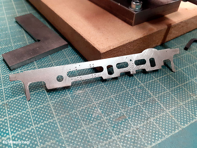
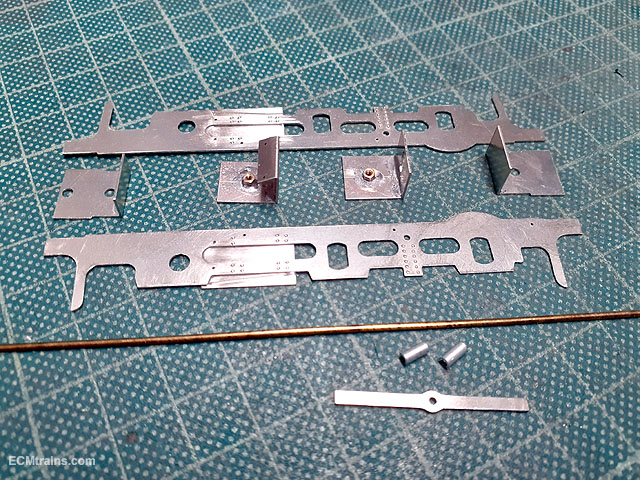
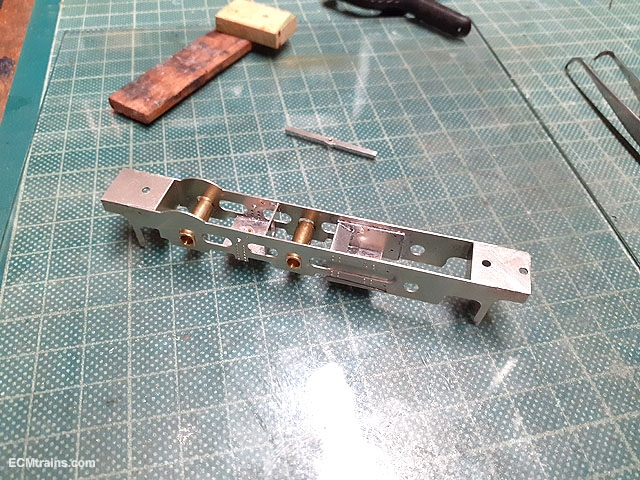
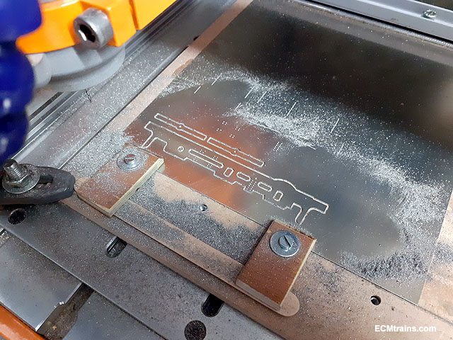
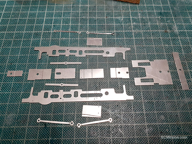
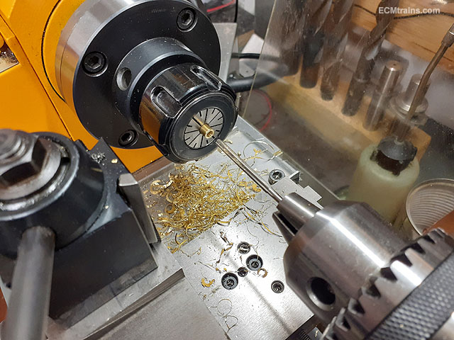
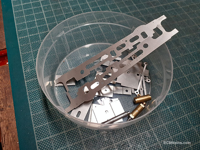
Main chassis parts and the wheel bearings have been machined for the new chassis described above;- Chassis frames being machined out of .45mm nickel silver sheet. All the parts removed from the sheet and edges cleaned up. The coupling rods are in two parts and have been half cut for the overlap on the centre crankpin. The frames have been half drilled .5mm for embossing the rivets and a few .5mm holes drilled through for construction alignment pins. Also the front and rear frame spacers have tabs which fit in corresponding tab cuts in the frames which should aid construction. The two front axles run in full frame width brass bearings, cut from 4.74mm (3/16'') brass rod. The bearing rods are drilled and reamed to take the 3.1mm (1/8'') axles. Flats are milled on the sides of the bearing rods which will fit into the slots in the frames to allow up n down compensation movement and stop the bearings from rotating. There is an old 3.1mm axle in the bearing to stop the vice pressure deforming the bearing. Bearings complete with an axle test fitted. An oiling hole is drilled in the centre of the bearings and the centre axle bearing is 1.5mm shorter than the front to allow a bit of side-play for the curves! Next will be a bit of riveting, folding, fitting & soldering. Eoin
-
He could paint CIE on the side Eoin
-
I reckon it's a tension winch, for pulling fences or holding down! The fact it has wire on the drum, it's last use was most likely on a fence. A lifting winch would have gears to lighten the load on the operator, and a much larger drum to hold long cable...... Eoin
-
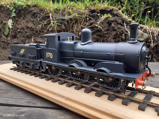
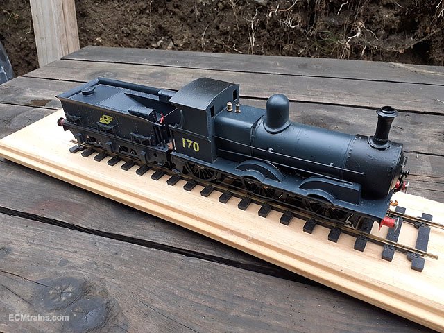
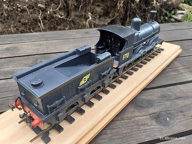
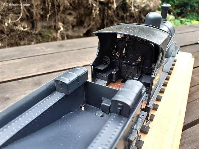
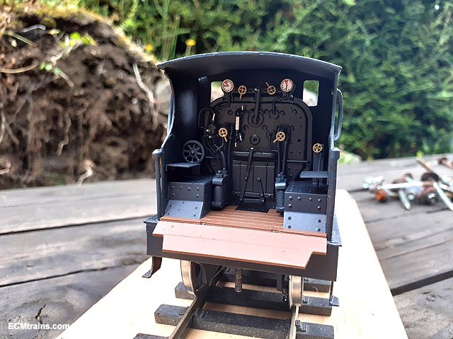
In the final throws of the J15 '170' rebuild;- All parts top coated, lacquered and left sit for a week to harden off. Gauges were completed and epoxied onto the backhead. All the cab bits going in. Chassis assembled and ready to run. Final assembly will happen over the weekend, some paint touch ups need to be done and it's just about complete!....... Eoin