murrayec
-
Posts
2,775 -
Joined
-
Last visited
-
Days Won
70
Content Type
Profiles
Forums
Events
Gallery
Blogs
Everything posted by murrayec
-
The coupler frame has jumped over and behind the 'bedoink' on the side of the underfloor, the coupler frame can be pulled forward against the spring until you have the corresponding 'bedoink's' on the coupler frame ahead of the underfloor ones, use a small screwdriver if needs be to guide them into position. This can be done with the bogie in place. The 121 is for HO/OO track, check the back to back dimension on the wheel sets- the dim should be 14.4mm approx. If this is OK you need to look at the track- is the curve to tight (2nd radius is the minimum it will run on), does the track need cleaning, is the track damaged...... the most likely one is the track radius. Eoin
-
Hi Dane, About 3 weeks ago I saw a box for the two car Commuter Set in Marks Models, in their Greenogue shop, maybe give them a ring to see it's available. Eoin
-
until
-
The date for next months Fair;-

-

GSWR/GSR/CIE Six-Wheeled Coaches - ECMbuild in Gauge OO
murrayec replied to murrayec's topic in ECM Model Trains
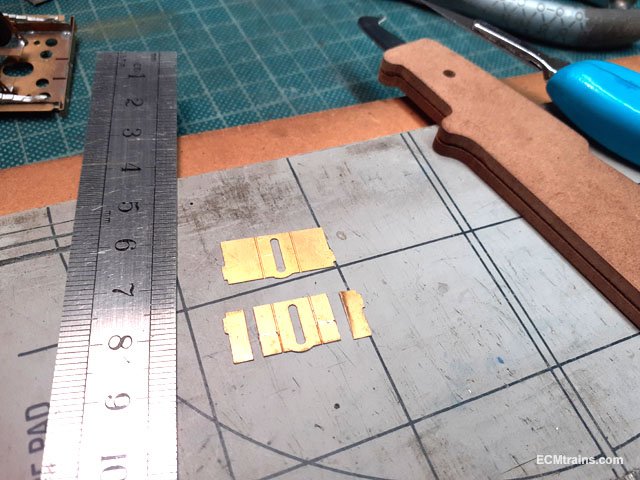
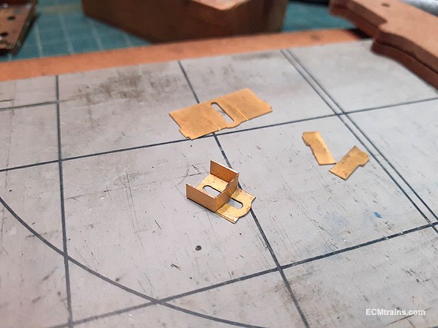
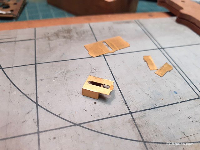
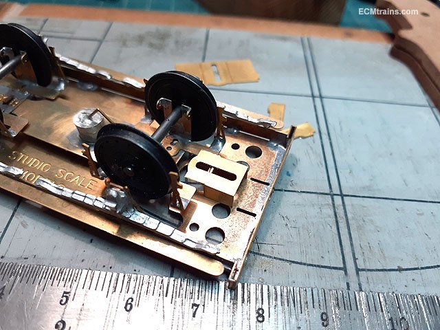
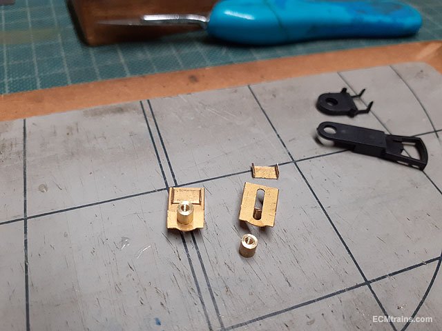
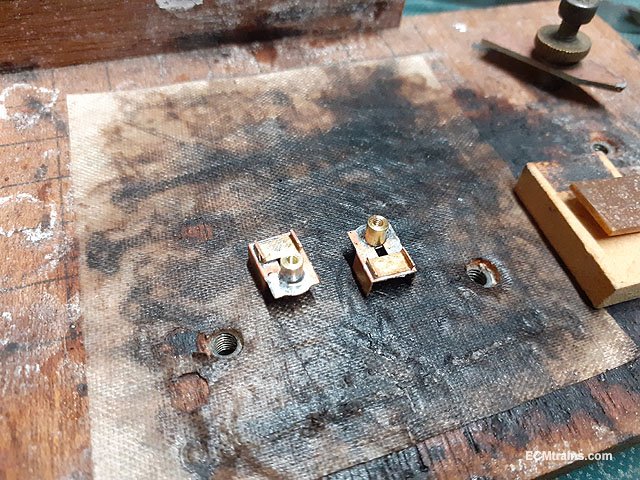
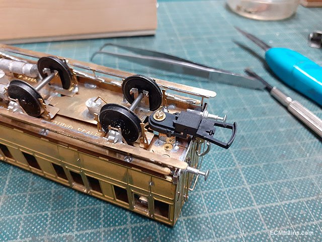
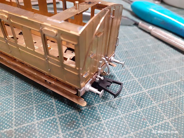
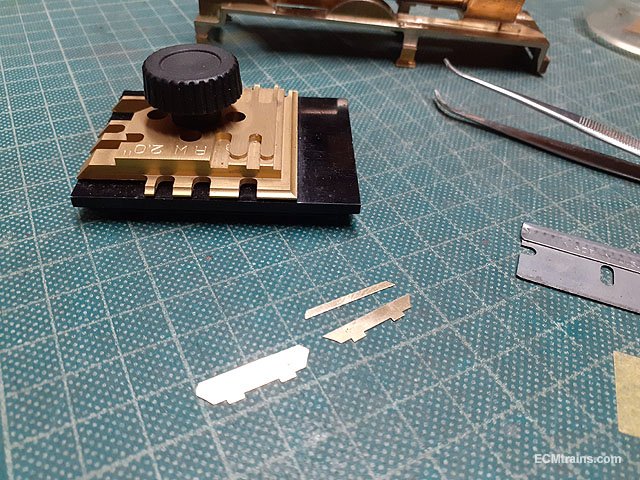
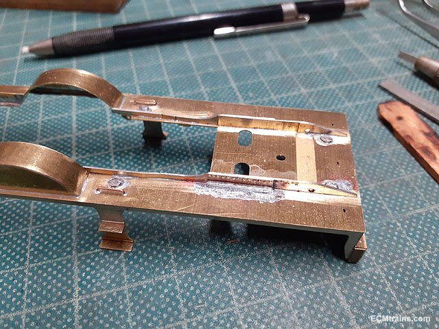
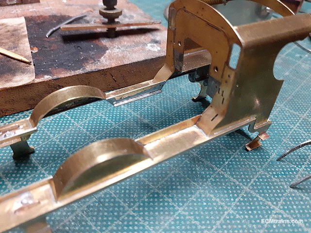
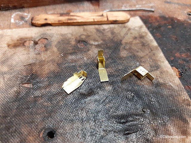
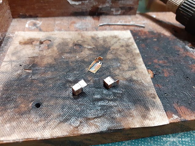
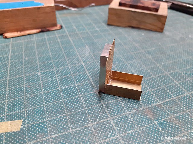
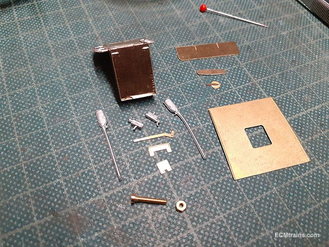
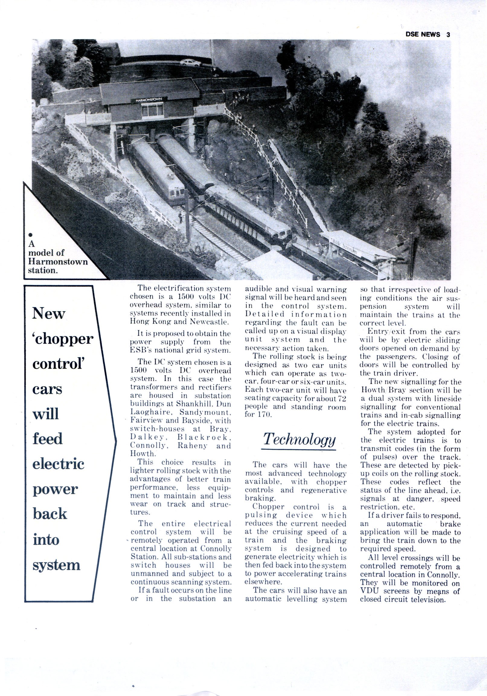
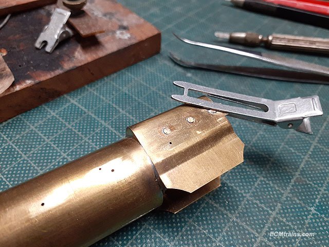
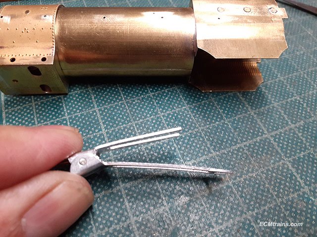
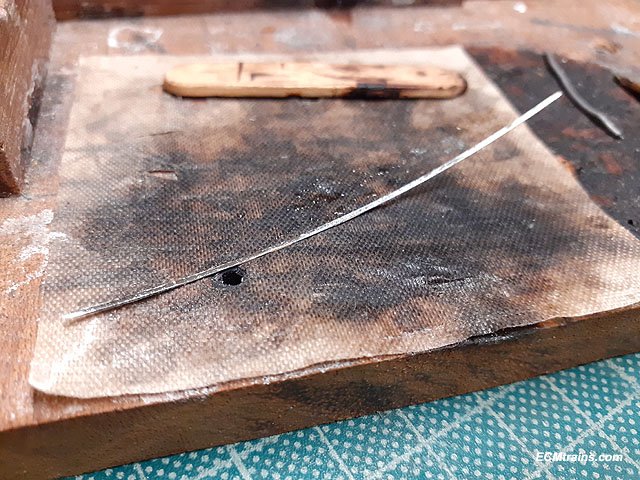
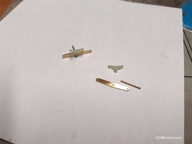
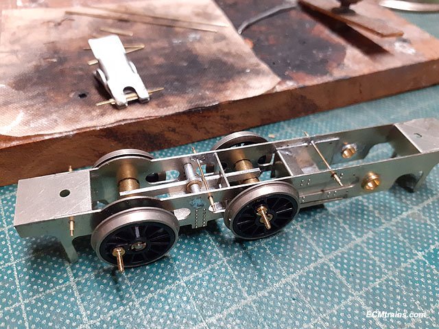
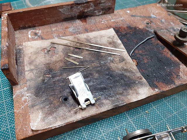
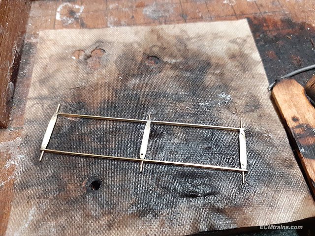
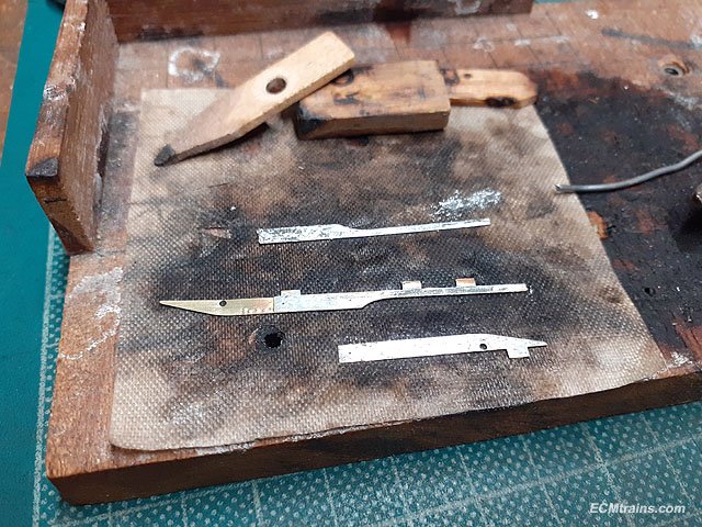
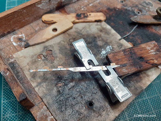
This is how I resolved the coupler issue;- Using the mounting part from the kit I cut it down to suit the Dapol coupler height. Then cut back the sides 6mm from the front along the half etch line and folded them in under the coupler fixing plate. This allows the bogie frame to swing in above the mounting plate without obstruction. Testing the bogie swing and locating the position to solder the coupler mounting to the chassis. Tapped spigots made up and using the offcuts to hold the Dapol spring plate in position. Soldered up. Soldered onto the chassis with coupler installed. This setup now has the coupler box flush with the buffer beam. Eoin.
-
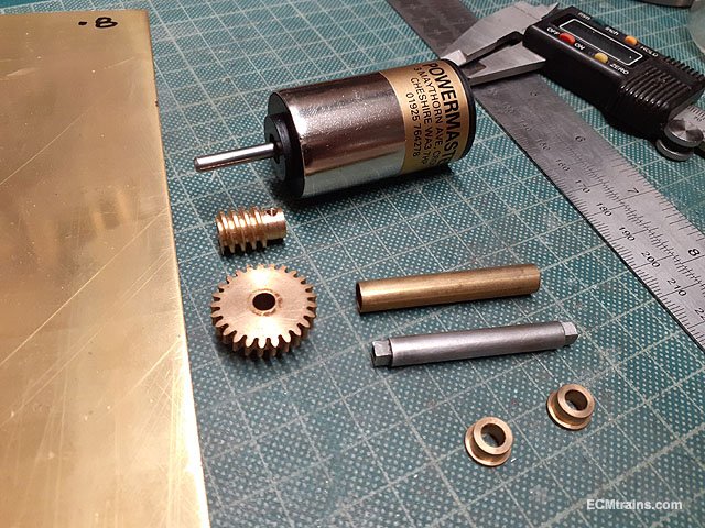
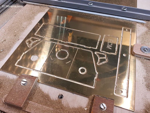
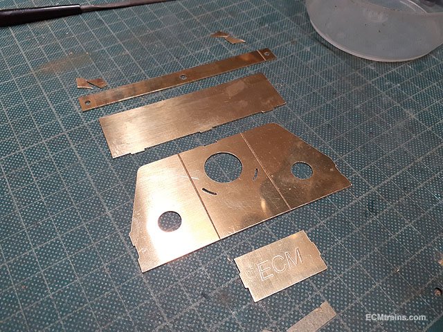
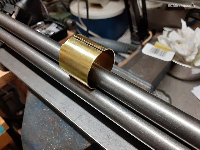
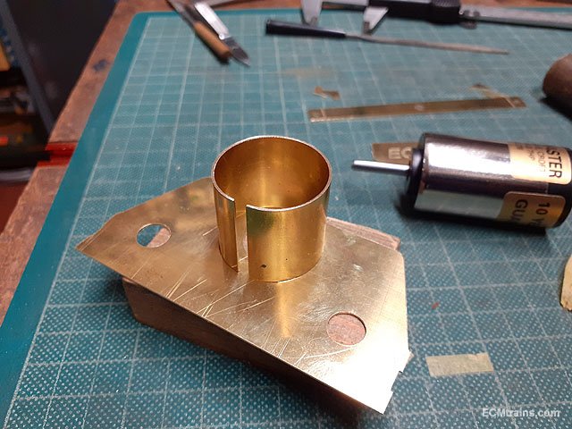
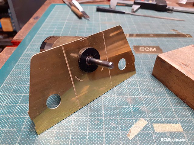
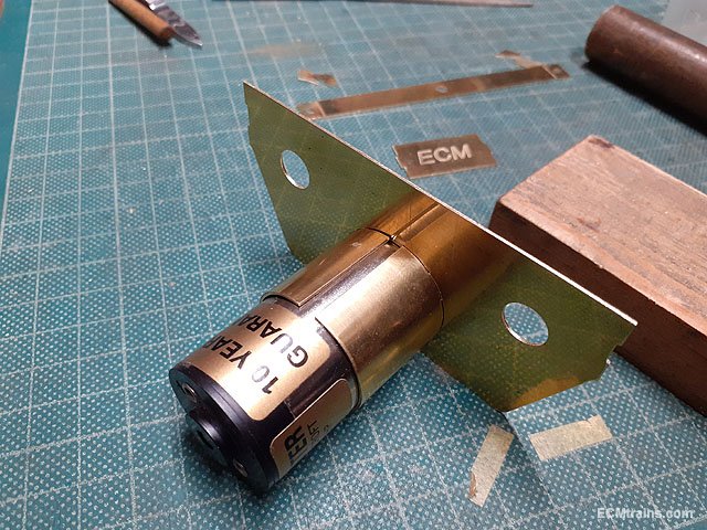
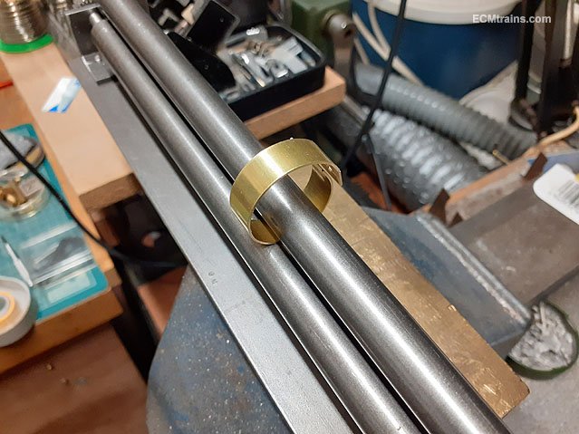
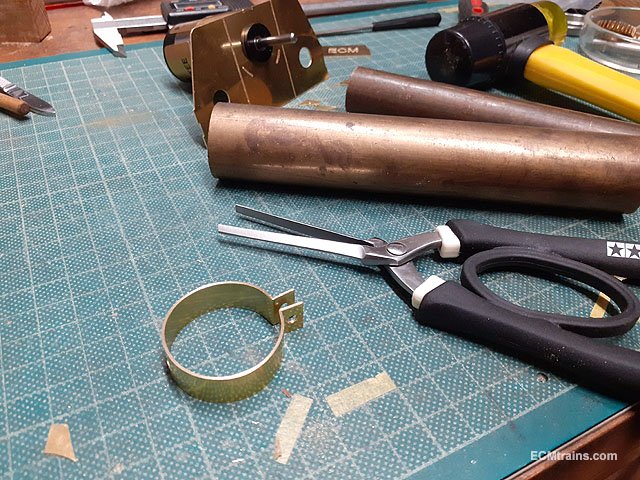
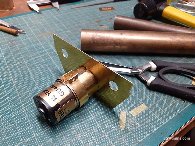
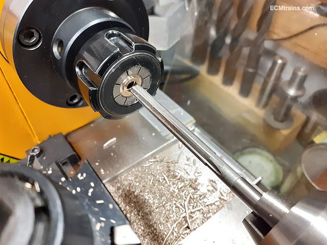
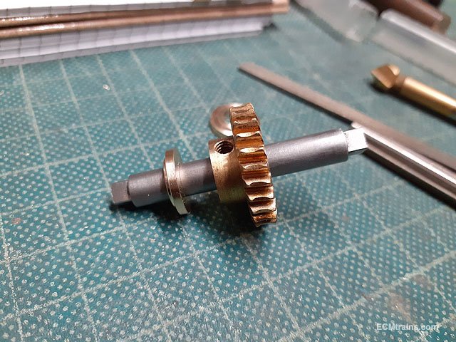
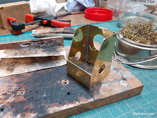
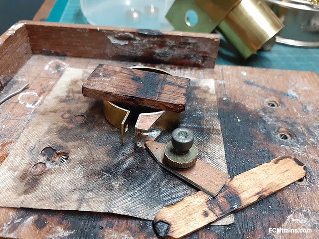
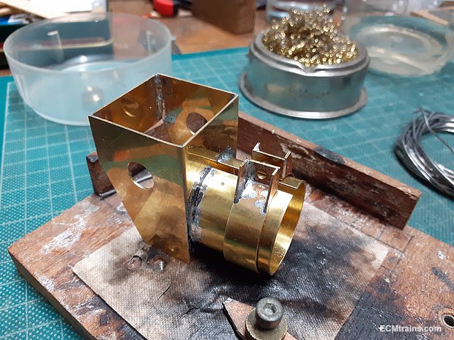
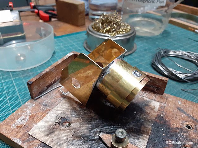
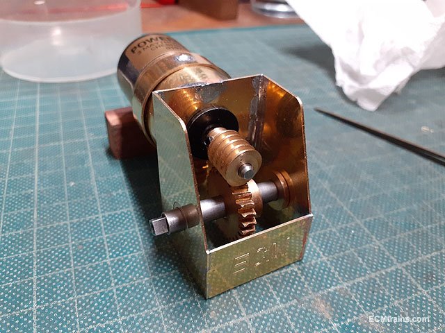
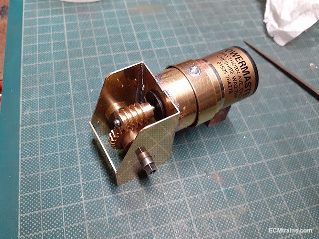
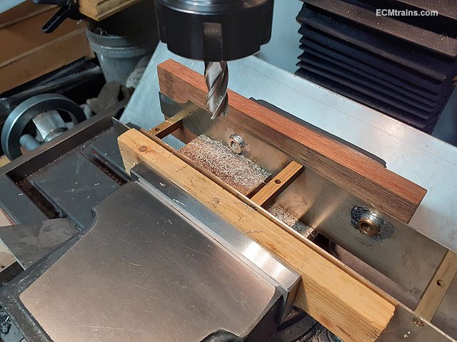
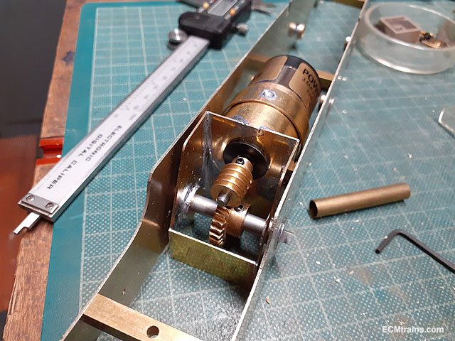
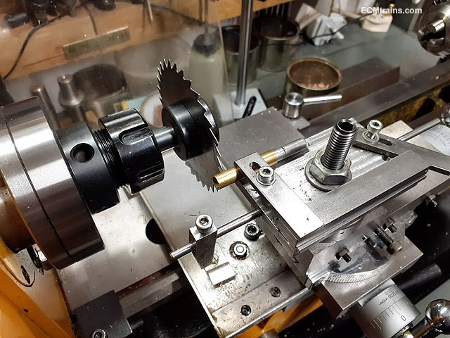
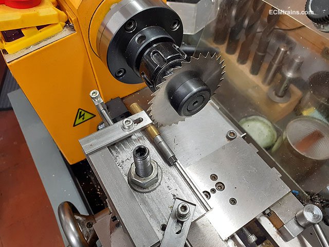
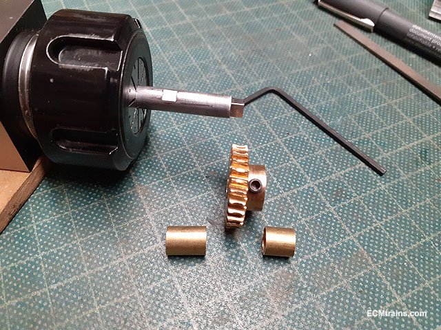
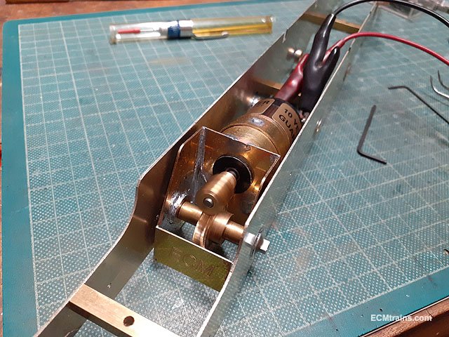
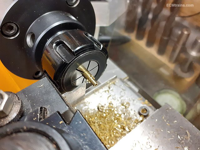
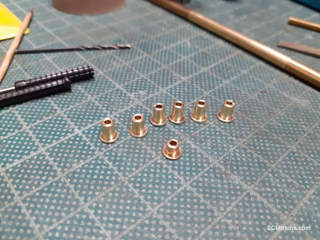
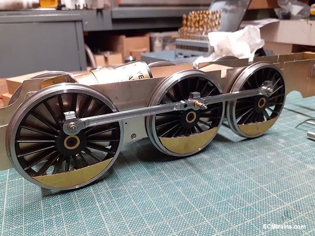
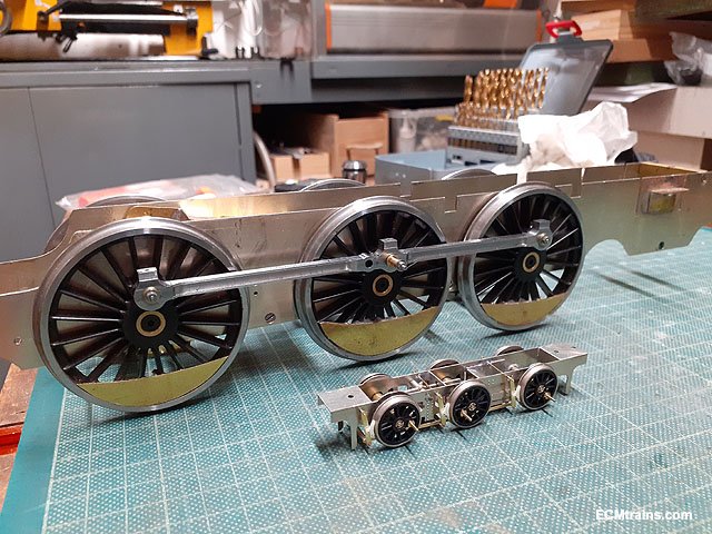
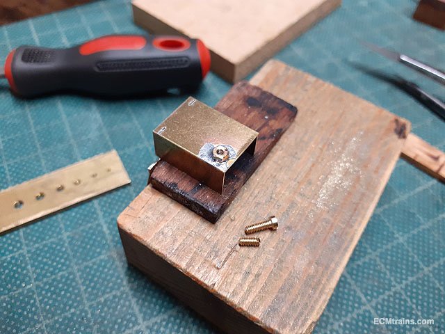
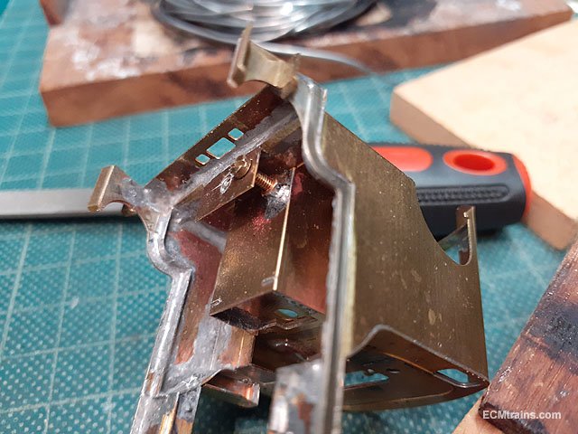
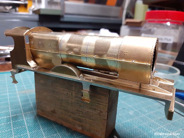
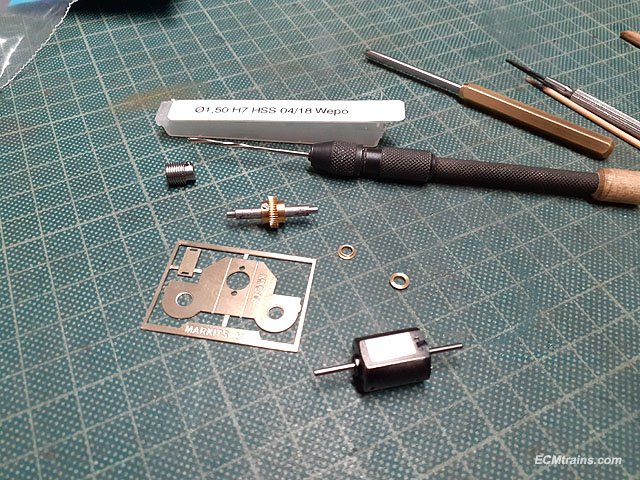
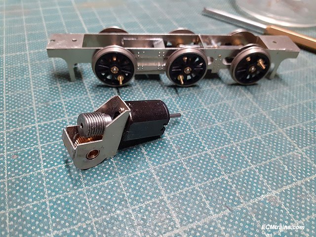
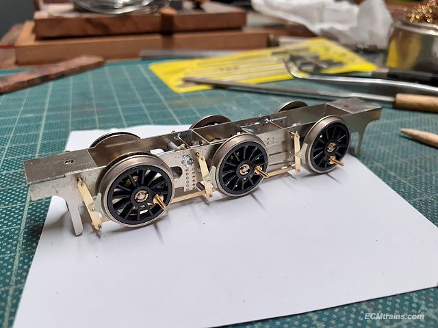
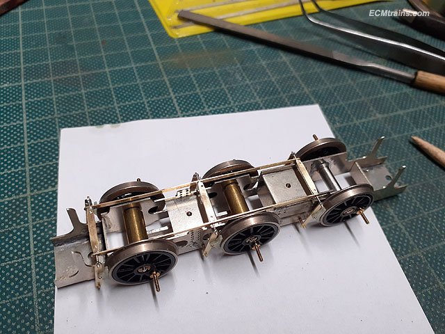
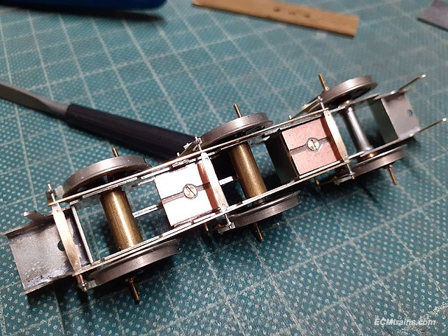
Motor and gearbox is next;- A hunk of a motor, a worm and axle gear were provided, the motor has no mounting screw holes so a gearbox with a sleeve motor mounting was designed up. The gearbox frame parts being cnc'd from .8mm brass sheet. All cleaned up. The sleeve mount will be soldered to the frame with the aid of tabs n slots, and the fold lines are half cut to aid folding. Rolling up the sleeve. A bit of fettling and it fits. And so does the motor, very snug, the clamp strap will only have to pinch it. The sleeve clamp strap being rolled up. The strap flats being folded where the bolt will be fitted. Testing. Axle bushes for the gearbox frame being turned from brass rod. And reamed to the axle size. Testing one of the bushes on the axle, the axle gear had to be drilled n reamed also. Frame folded and soldered. Soldering the gussets on the clamp strap. Motor sleeve and strap soldered on. The strap is soldered to the sleeve. Assembled up, I waited until the gearbox was in the chassis frames to solder the axle bushes in. Skimming off the inside face of the axle bushes to fit the gearbox in. The gearbox fitted in the chassis, now the bushes were adjusted and only tack soldered in- as further adjustments may be required, was required! Measurements are also taken to cut that brass tube, beside the chassis, for axle spacers on both sides of the axle gear. Cutting the tube, the lathe is great for this, using a slitting saw with the brass tube on a home made clamping table mounted where the tool post should be. Tubes cut and a flat was milled on the axle for the gear grub screw to lock on. Assembled again and powered up. Next is to assemble the wheels and fit the coupling rods, but first we need extra long crankpin bearings. Back to the lathe to turn up 6 bearings from brass rod. The rod was drilled and reamed to fit 10BA screw size and then turned the outer diameter to size , a parting tool is used to do this, once the first bearing is turned to size the topslide dial is noted and marked so that the next 5 bearings are turned to the mark and all come out the same size. All six with a Slaters bearing in front for size comparison. Coupling rods installed but cannot set the quartering on the rods because there is so much flex in the chassis! I first need to install the valve gear motion frame and a few 90 deg frame spacers here and there to stiffen things up. Another shot with the Gauge OO J10 chassis to give some scale to this beast! Eoin.
- 30 replies
-
- 10
-

-

-
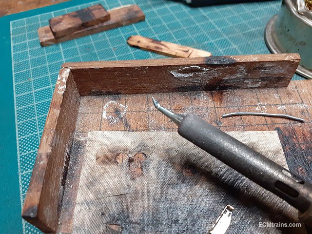
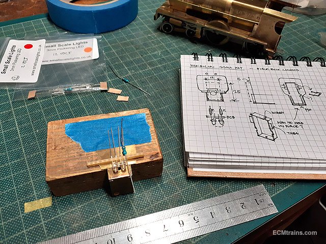
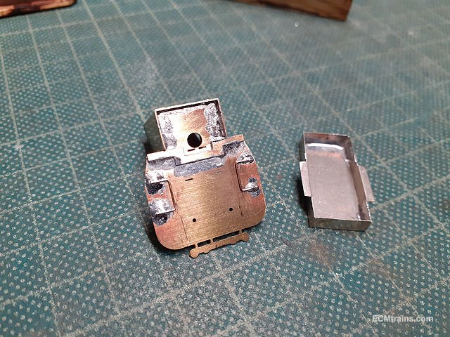
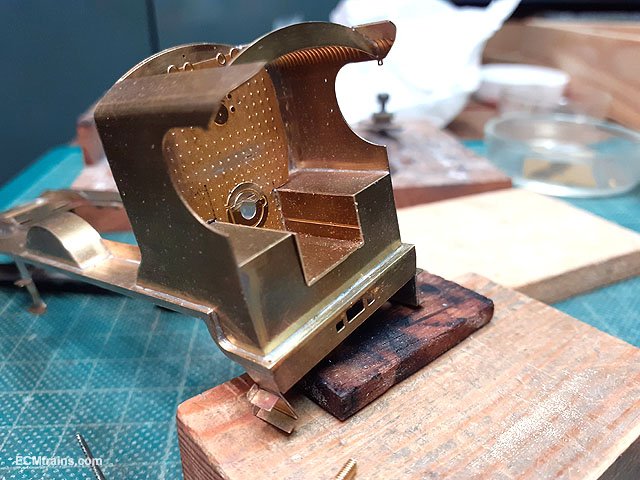
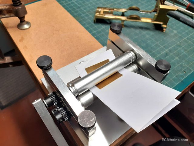
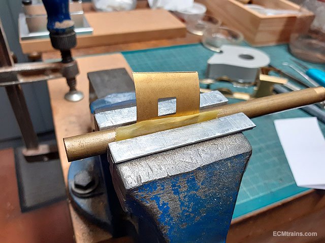
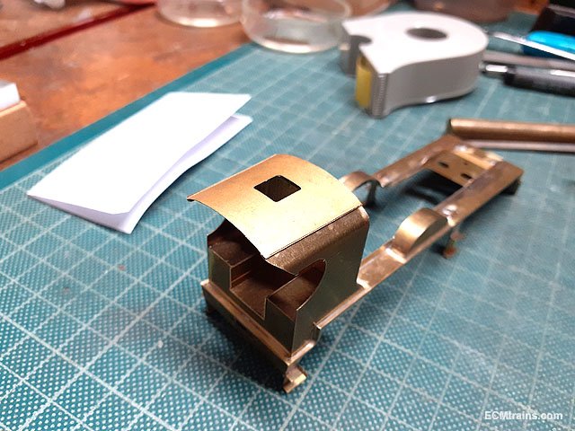
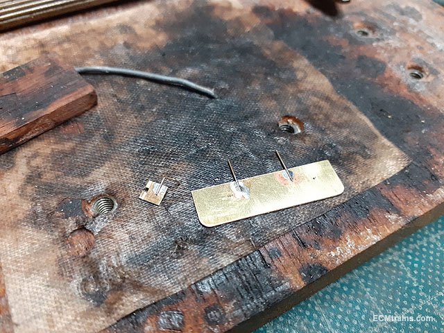
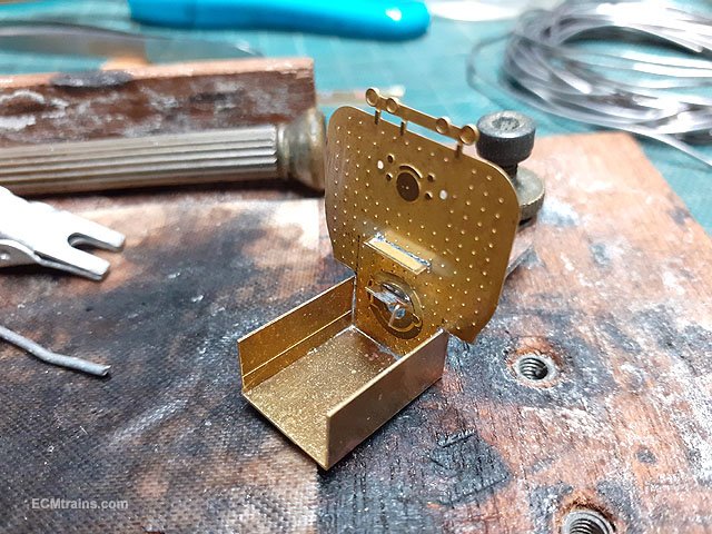
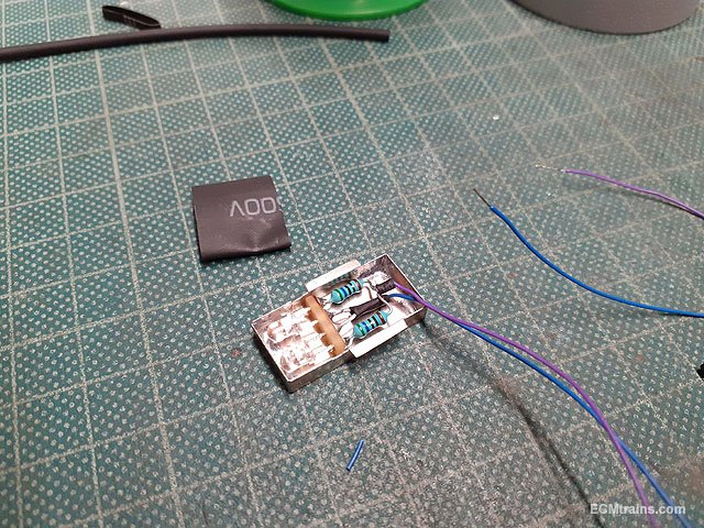
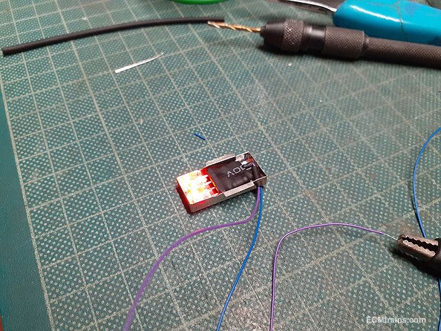
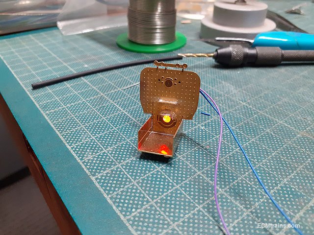
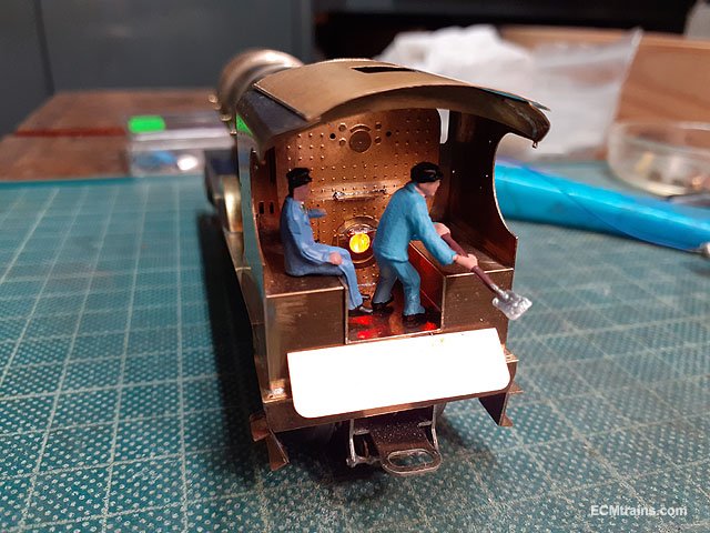
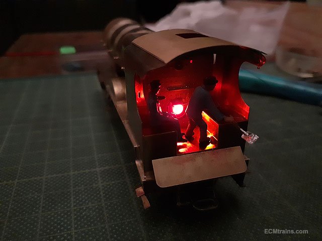
The crew reported in today to run a boiler test;- More on that later. More detail parts being set-up, firebox base covers, oil pump boxes, sand box lids, cylinder footplate covers and cab front reach rod housing. The firebox base covers require resizing so the top part is snapped off at the half etch line. Cylinder footplate covers and box lids being prepared for sweat soldering onto the running plate, a dab of solder is applied to their locations on the plate. Soldered on requiring a bit of a clean up. Firebox base covers soldered between the driving wheel splashers. Oil boxes and reach rod cover plate folded up. And soldered. This is the cranked soldering tip I mentioned previously, it's very handy in tight spaces like the oil boxes. A bit of a clean up on the above parts, the oil boxes will be epoxied on after the painting is complete. Next to the cab internals, we're going to have a 'Live' firebox, as I'm sure you guessed from the picture above. First thing was to work out the lighting stuff, the backhead will have to be moved back in the cab to allow for the lights- the motor gearbox is in the way! The bulbs will have to be enclosed in a box as light would flood out under the loco and from behind the backhead! The backhead was taped down to work out how the lights will work so that a cover can be designed to close them in. Red & orange flickering leds are being used and the cover will be made from .19mm NS sheet. With the plan sorted I cut out the NS part, folded it up, and soldered it. The plan included for PB wire clips soldered onto the back of the backhead to hold the box in place by it's wings! Assembled. With that sorted the cab floor had to be trimmed back and other cab parts assessed and prepared. First the floor fixing- a 10BA nut was soldered on the underside and a 10BA screw sized for fixing the part in. The floor and the splashers sides need a bit more filing at the back, but I'll come back to that later. Next I heard about the crew coming to do a firing test so I bent up the roof to give them a bit of cover! Rolled to ruff shape, 2 sheets of paper in there to protect the half etch edge detail. Edges bent over a 12mm dia brass rod in the vice. It fits. The fire box door was set up with a bit of bent .3mm pb wire for the opening handle and the fall plate had .3mm pb wire soldered on, which are bent at 90 deg down and pass through corresponding holes under the cab floor, the floor holds it in. Backhead shelf and fire door soldered in. The fire box light assembled on a bit of pcb strip board and been tested for fit. All is covered with some shrink to avoid shorts and a 2mm dia hole drilled out the side for the wires with a bit of shrink in the hole for protection, and power testing. Testing again mounted on the backhead. The crew at work! They were having so much fun the stayed on till late...... Eoin.
-
I had a 'kettle', I heard that they could go backwards if the HT leads were set up out of sequence! Lovely bike so never tried that...... A friend had a Suzuki GT though- when he switched the HT leads the bike ran backwards.... Eoin
-
I had a BSA years ago- sometimes at low tick-over one would hear a glunk which indicated that the crank is rotating in the opposite direction!! One then had reverse in all gears!! Eoin
-
One of the boons of being in a club is that it affords members access to models and layouts that they do not own themselves, they may not have space at home for a layout, or have the capability for building one, or do not have the budget to buy all the models they desire- clubs can fill the gap.... In my view, here in IRL, Irish locos & stock are not in the majority- British, American, and Continental are the majority in that order. I base this off what I see in the clubs and what the majority of my clients and acquaintances run. Irish locos & stock are gaining appeal here with the new stuff available. One cannot use the IRM forum to gauge the interest, in my experience. I have mentioned this in another thread- about 10% of my clients use social media and that figure is about the same for people I know that run model trains.
-
Ernies Massive Irish 1930's to 2005 Photo Archive
murrayec replied to Glenderg's topic in Photos & Videos of the Prototype
Here is my guess;- The fact that the bottom section of the pipe is cranked out from the wall makes me think of a chute or discharge pipe, cranked out makes me think it was used to fill bags or a wagon! In 1970 the company attempted to replace the narrow gauge railway with a Ponndorf compressed air system to carry spent grains from the brewhouse to an area where they were collected by farmers- It did not work as the compressors burnt out. Could this be a discharge pipe from that system, and could the item sticking out of the pipe be a handle to a plug closing the pipe when not in use?? Eoin -
This month's Fair date;-
-
@Westcorkrailway Unfortunately Silver Fox use Impact adhesive (not sure on this model) to stick bodies to the chassis- the adhesive does let go after sticking cocktail sticks in and along the join, gradually mind you! give the glue some time to expand. If you do get it open show some photos and we may be able to help....... Eoin
-
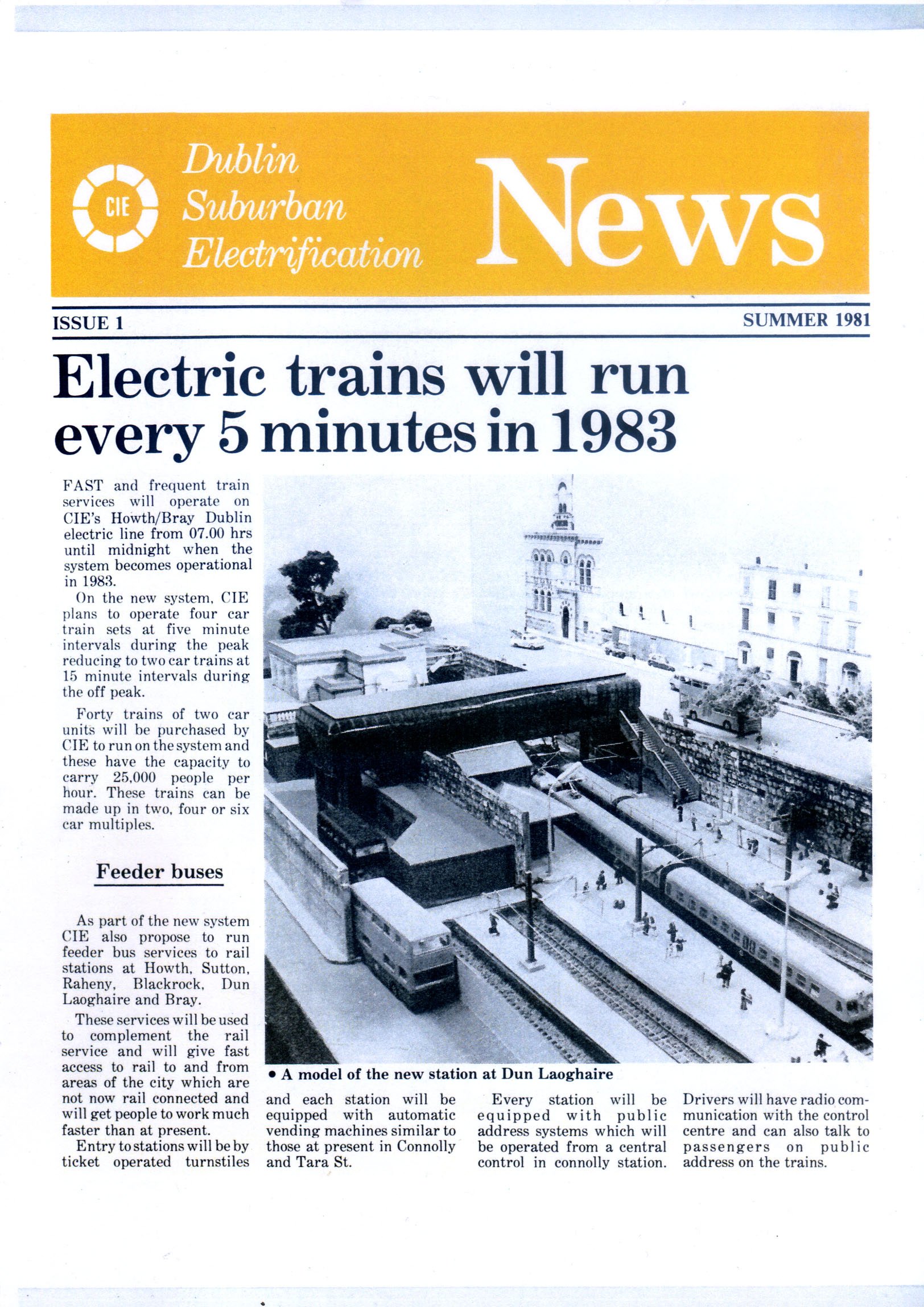
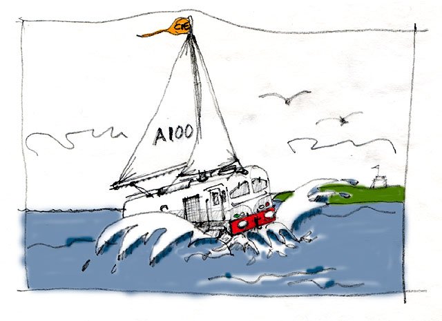
It was built by a chap in the South Dublin Model Railway Club back in the 80's to promote the coming of the Dart, it was recently restored by the Club and exhibited at the last Blackrock Model Railway Show;-
-
@islandbridgejct here is what your looking for;- Eoin.
-
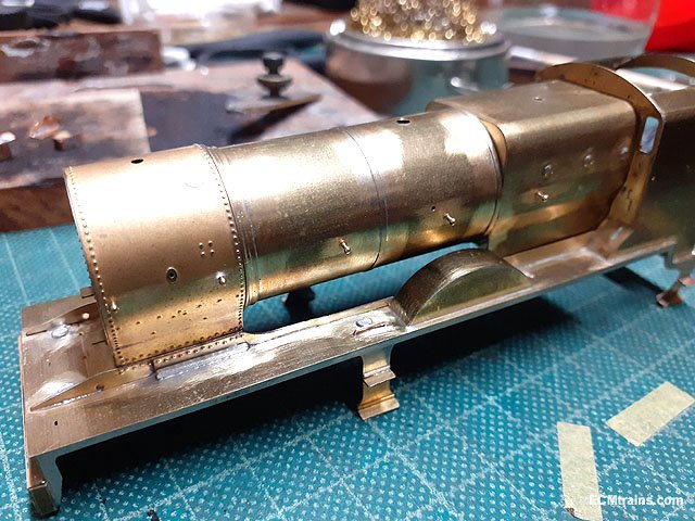
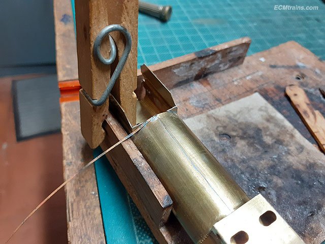
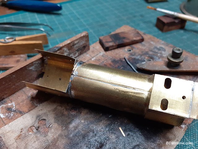
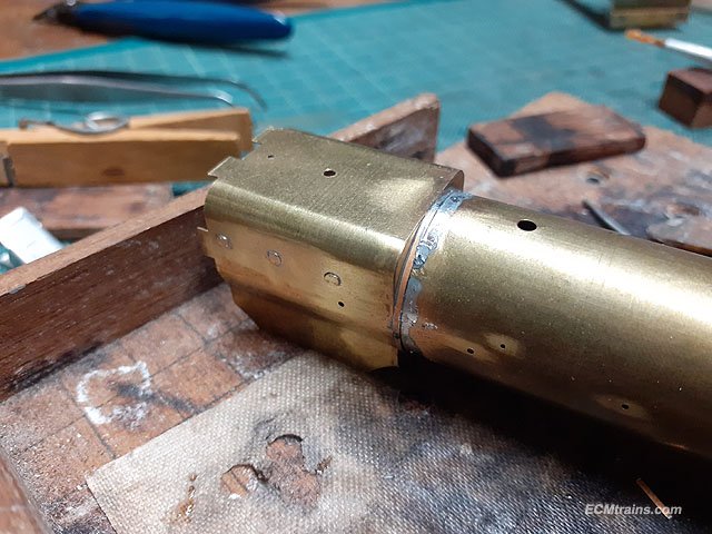
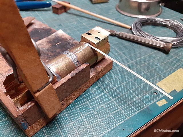
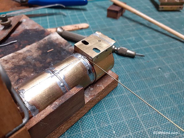
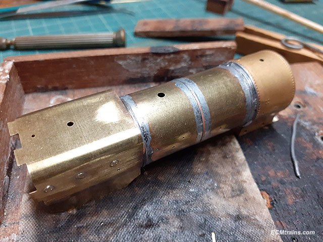
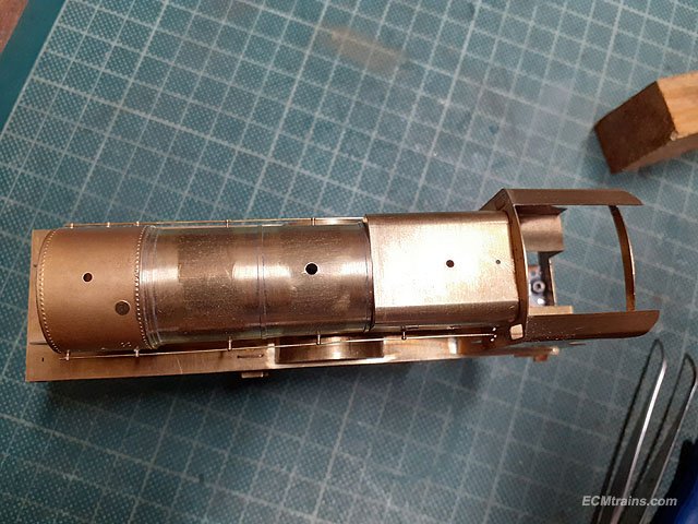
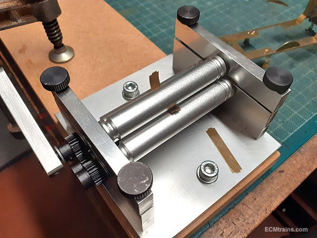
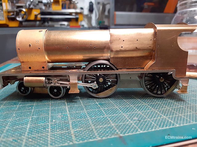
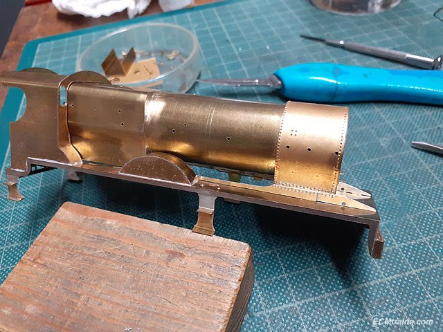
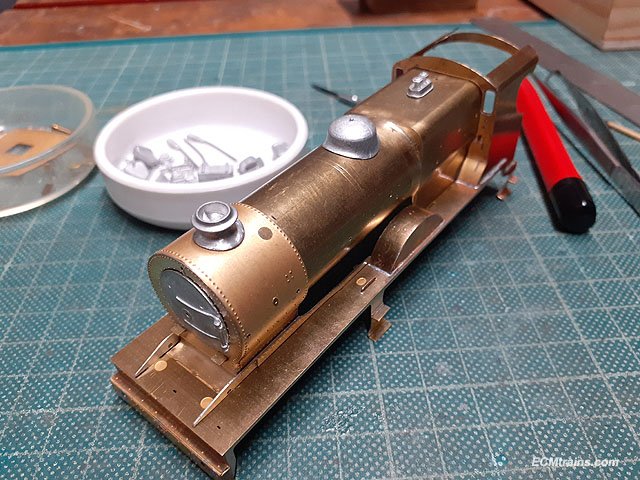
Detail parts going onto the boiler; Washout covers being soldered onto the firebox, clamped with a Dinky clip over the marking holes then soldered on the inside with the solder wicking through the hole to fix the part. The clip has odd legs so that it doesn't get in the way for soldering. Boiler bands being prepared with a coat of solder before wrapping them around the boiler. End soldered on and the wrapping commences using a stick to hold the band while the solder iron is applied, first tacked in a few places around the band and then soldered throughout. First band done. The middle band was done the same way using the previously scribed lines to line it up. The smokebox band is larger with a moulded rebate, when it's on a.... .... .5mm brass wire is wrapped over and soldered on top of the band up against the smokebox to add further moulding. Bands done. And cleaned up with scratch brushes. Sizing up the boiler handrails and knobs, .4mm brass wire is being used here as the handrails will be chemical blackened on completion. Knobs are soldered on the inside with one being difficult- the front one is right up against the smokebox front which is hard to get the soldering iron in at, but I do have a cranked tip for the iron which helps. Rails on, and the running plate front chassis frames where soldered to the plate after a small bit of filling at the back to ease the fit against the smokebox sides. Eoin.
-
@Westcorkrailway As George says if they are waterslide type use warm water only- if printed on a transparent carrier sheet cut each decal out of the sheet in a square or around the decal, if they are printed on the paper carrier sheet only, cut them out on a square of the paper carrier. Immerse in water for 30-60 secs or until you can slide them on the paper carrier, leave them on the paper carrier slightly slid off and holding the paper carrier with a tweezers to transfer it to the model and slide the decal off the paper carrier onto the model. As Galteemore suggests you can also use Microsol solution- but be careful the solution can soften the decal if left for to long and it may go out of shape! Use a cotton bud to squeeze the water out from under the decal, dabbing or rolling the bud on edge, working out from centre of the decal to its edge, this removes water and air from underneath- do not rub the bud across the decal cause the decal will move or tare. Some waterslide decals benefit from a coat of varnish or lacquer (not water based) to protect the ink before you immerse them in water- nothing worse than the decal ink coming off on the bud! Use Microsol later after the decal has dried on the model, this will help it to stick down better, and again using a bud as described above. If the decals are not lacquered this process can destroy them. One other thing to consider- they may be rub off decals?? like the way Letraset works! Eoin
-
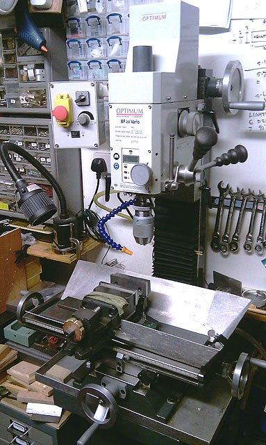
Hi Colin, Arceurotrade do a mill but it's quite expensive! I have an Optimum BF 20 Vario mill/drill, which is perfect for model stuff and small fabrication jobs. Again all the main tool suppliers do this machine and it's a lot more economical than Arc. I'm sure there is an agent for Optimum in the UK? Here is a link to a comparable machine and others to select from on this site, these guys do a mini lathe also;- https://www.warco.co.uk/milling-machines/303103-wm-12-small-engineering-metalworking-milling-machine.html Eoin
-
It's a 'Mini Lathe' CL300M 180mm swing, 300mm between centres, by Clarke, this type/size of lathe is available from all the main machine tool suppliers. Arceurotrade.co.uk do a version SC3 which comes with a number of upgrades, like I have done to mine, as standard if your thinking of investing;- https://www.arceurotrade.co.uk/Catalogue/Machines-Accessories/Lathes/SIEG-C3-SC2-SC3-Mini-Lathes/SIEG-SC2-SC3-HiTorque-Mini-Lathe-Belt-Drive-with-Brushless-Motor A standard Mini Lathe costs less than the SC3 but will not have modifications done- which you can do yourself. I have done; Taper bearing headstock upgrade. Pinned and added lock screws to all gibs. Carriage lock. Added oilers to the leadscrew. Added a cover to protect the leadscrew from swarf. Changed the standard tool post to a quick change post. Changed the plastic handwheels to cast iron type. Added and made a huge amount of tooling, too numerous to list here- the best accessory for the model building we do is a set of collet chucks- ER25 has collets from 1mm to 16mm if you buy a full set, there are also imperial collets. Hope that helps Eoin
-
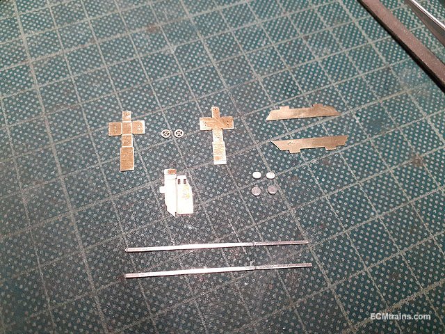
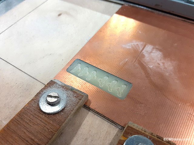
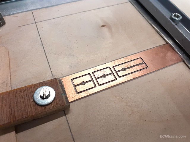
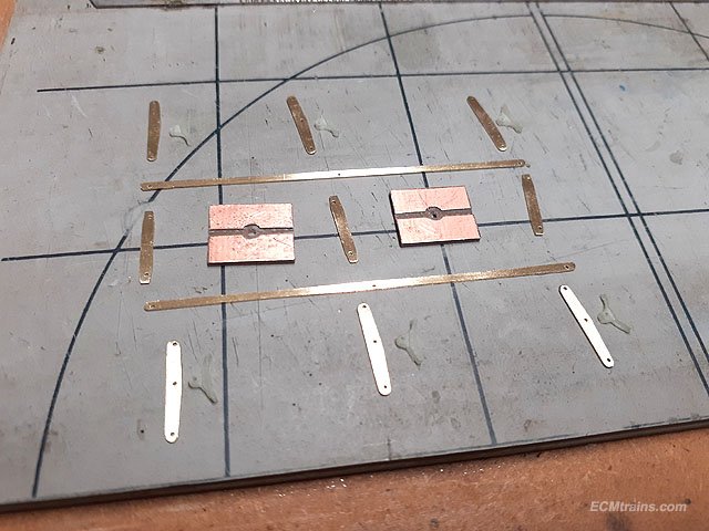
Motor, gearbox, brakes and pickup boards being made & installed;- Gearbox holes being sized for the axle bearings. Unit soldered with motor attached. Brake shoes being cut from 1.3mm pcb board, the copper cladding was first milled off and then the shoes cut. Pickup boards being cut from .7mm pcb board. Brake rods & hangers cut from .3mm brass sheet. Brake shoes being fixed to hangers with .5mm brass rivets. .5mm brass wire spiggots to hang the brake hangers from are soldered into the frames with a 2mm long brass tube to hold the hangers in position out from the frames. Brake rodding being soldered up. Soldered. Finally shoes on, the assembly is set up so that it can be removed for painting. There is not much free space to get the pickup wires out to the wheels with the rods in the way.... but I think I have a plan! Pickup boards screwed onto the frame spacers with 10BA bolts. More later..... Eoin
-
This is sort of applicable again!! Eoin
-
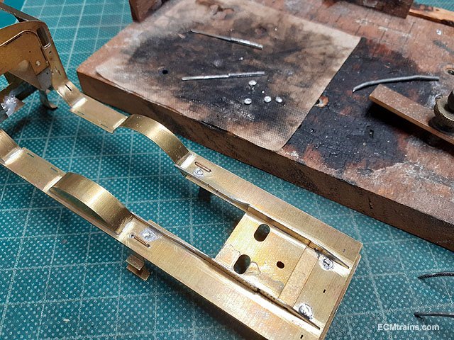
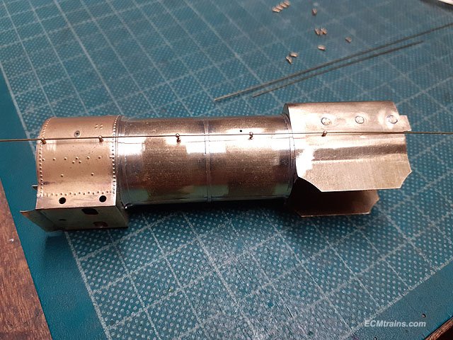
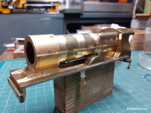
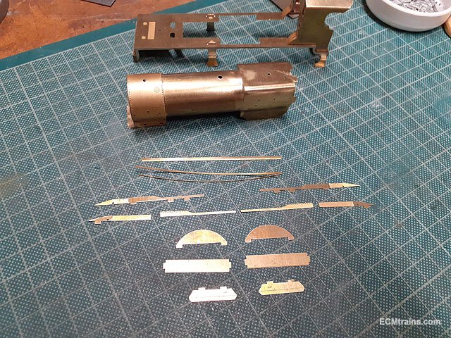
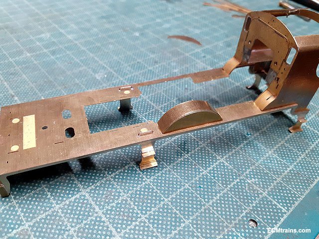
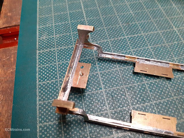
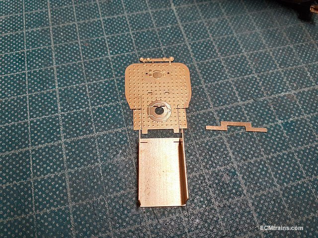
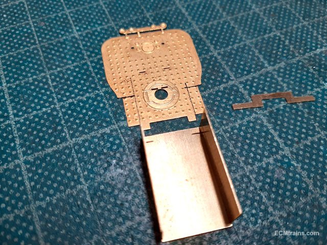
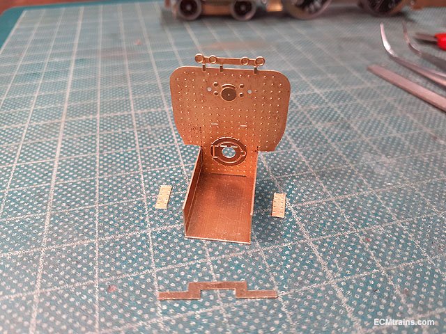
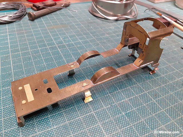
More running plate, boiler and cab assembly;- Running plate, boiler bands, splasher parts removed from the fret and cusp removed. Marking out the centre boiler band position (in the middle) on the boiler using the height gauge to scribe lines to aid soldering the band on vertically. Bending up the splasher tops and test fitting to the running plate, the tops are handed- the left side has etched marks for fixing the brake rod mount, and the outer edge of the tops have an etch rebate to fit over the splasher face. I set about fixing the rear body captive nut- as mentioned above the bolt in the chassis is not in line with this nut and the running plate would not sit down on the chassis. The scribed mark is where the nut n hole should be, so the nut was de-soldered, the hole dragged back to centre on the line with a file and the nut soldered on again in the correct position. It sits down now. Just about ready to solder the cab to the running plate but decided to check the fitting of the cab footplate and backhead first to make sure all is OK, as if adjustments are needed it would be easier to work on it separate from the running plate. The parts are cut from the fret, cusp removed and the footplate folded up. For 16mm gauge the backhead needs adjustment to fit into the footplate well, this is marked out on the part and the bits are cut off with a craft knife by scribing along the edge of a steel ruler a few times. Trimmed. That bit out front is a support bracket that will be soldered onto the rear of the backhead above the coal hole, it's ends just sit on the cab splasher tops so that this assembly can be removed. It's held in with a 10BA captive nut and bolt through the running plate- that's what the second hole is for on the running plate beside the chassis mounting, see photo above. Test fitted in cab after some adjustment. The cab and the splashers were then soldered onto the running plate, all soldering is done on the inside, but needs a bit of a clean up because the solder wicked through to the outside- later! Setting up to sweat solder the parts which make up the front chassis frames on the running plate, each frame has 3 parts to them, they are lightly face soldered first, then clamped in position and soldered up. After a clean up they are test fitted to the running plate with the boiler fixed on- just a tad to tight on the smoke box so they will need a bit of filing before fixing on. All the boiler holes have been sized to take the white metal castings, handrail knobs and other bits. The castings have also been cleaned of flash and moulding lines and are about ready to go on after the boiler bands are done. More later........ Eoin
-
I switched the lights on in photoshop! - a few selection marques with level adjustments for the headlamp beams, and some render 'lens flare' for the light glare and the flashing blue light....... Eoin