murrayec
-
Posts
2,737 -
Joined
-
Last visited
-
Days Won
70
Content Type
Profiles
Forums
Events
Gallery
Blogs
Community Map
Everything posted by murrayec
-
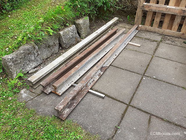
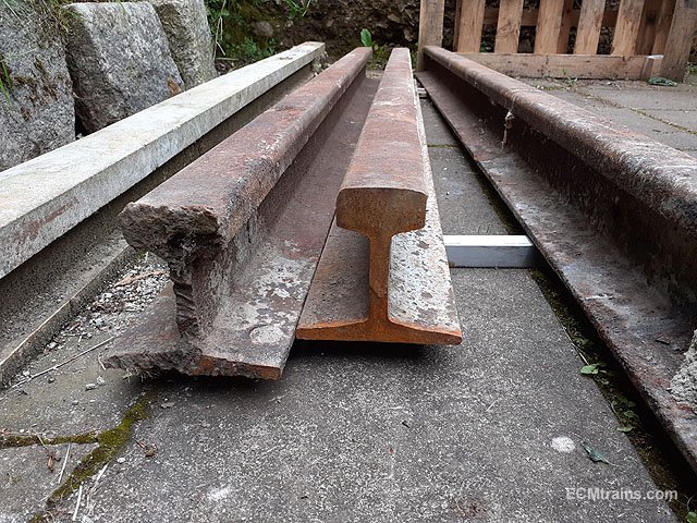
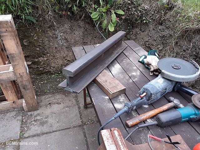
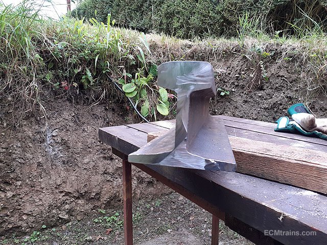
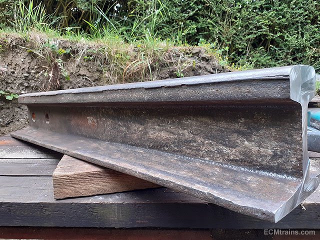
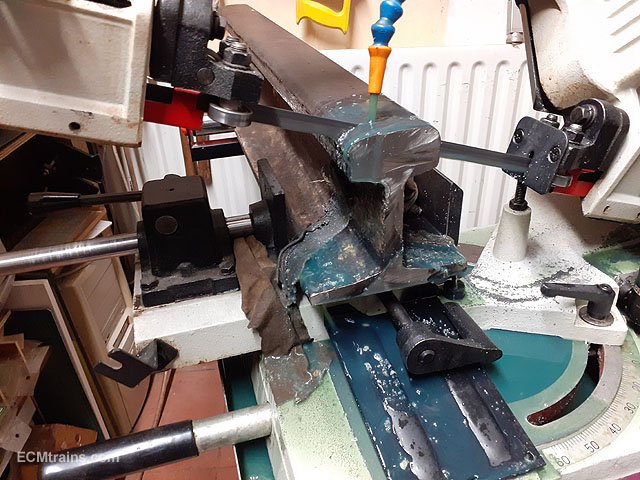
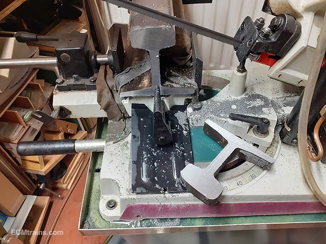
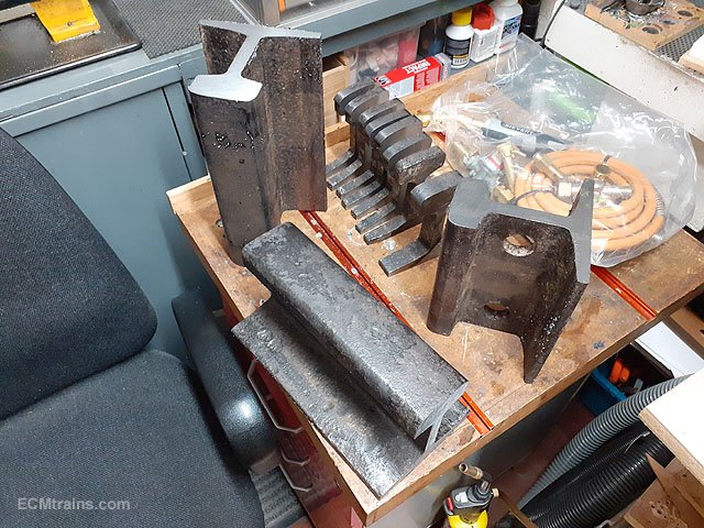
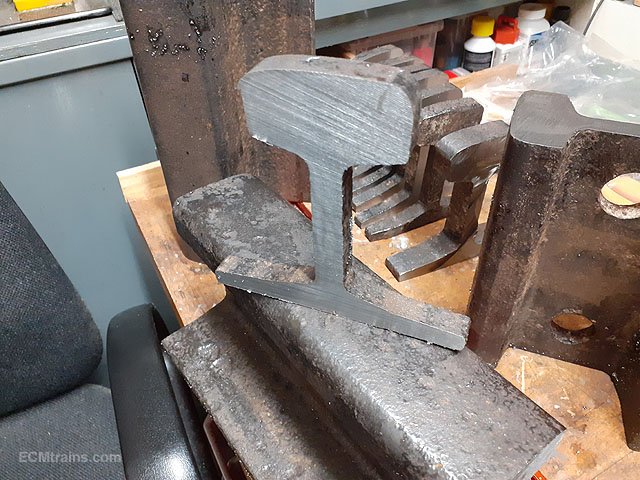
Many years ago while in my neighbours garage I noticed the roof was held up by railway track beams! The house is now being demolished for re-development and I scrounged one of the rails....... After chopping the rail into 3 pieces on the site, a bit of heavy lifting got them into my back garden. Out with the big grinder to chop some into manageable bits. This photo shows a bit of ware n tear on the top edge- so this rail was used. Onto the band saw to cut down to even more manageable size. The large bits will be fashioned into anvils and the small ones which are cut 15mm thick will be mounted on plaques for hanging on the wall. More to follow when I get a bit more processing done......... Eoin

-
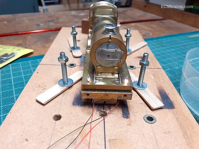
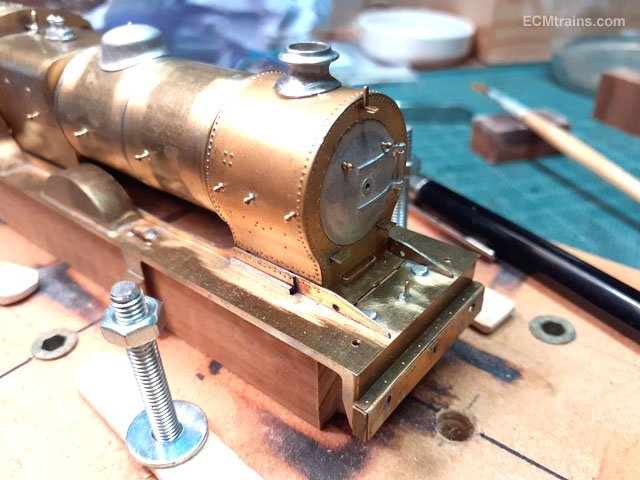
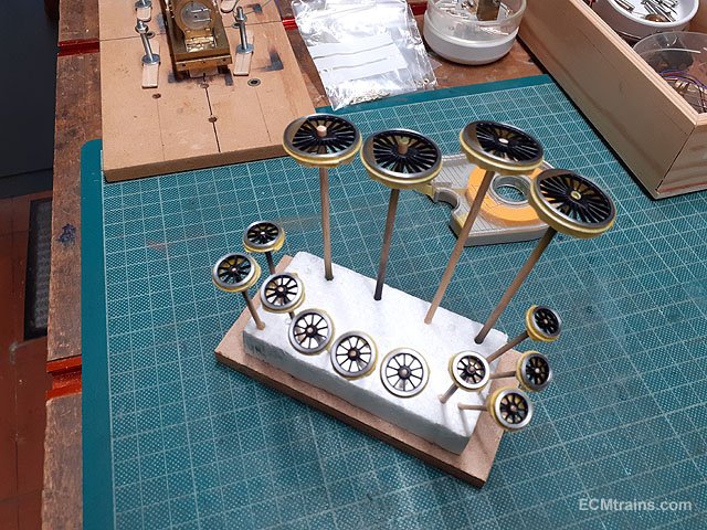
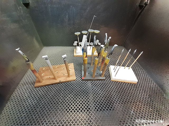
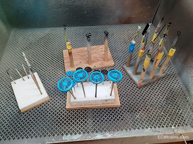
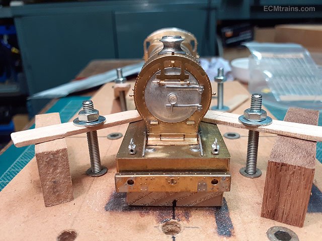
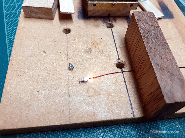
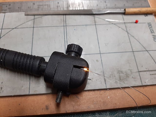
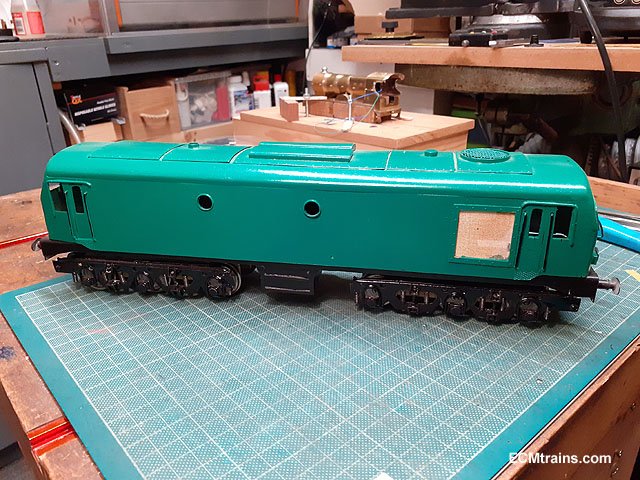
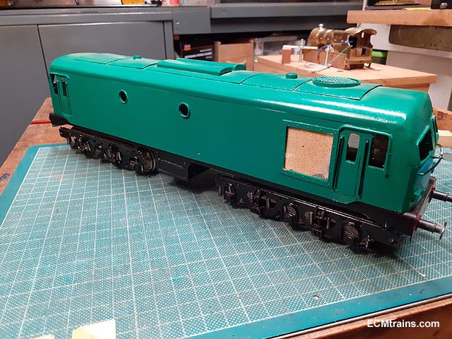
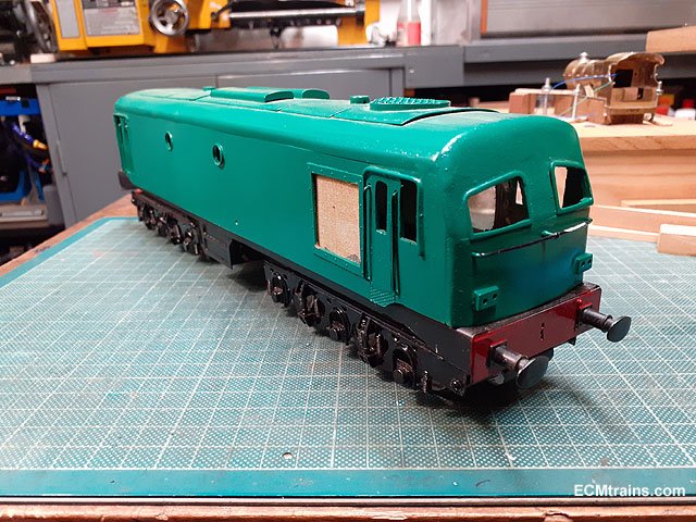
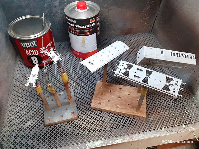
I worked out the front lamp mounting and commenced painting;- The LEDs under test, the lamps will be mounted on the running board using a bit of stripped wire insulation threaded over the LED wires and glued into the lamp base. The lamps will be epoxied on when painted and assembled. Centre front lamp bracket soldered on and this photos shows the drilled holes for the LED lamps. Steam dome and safety valves were epoxied on, the whistle assembly was soldered onto the firebox with the steam pipe dry fitted into the cab front, also the safety valve steam deflector plate was epoxied on the valves. Wheel threads masked up for painting. Wheels and small parts etch primed and under-coated. First colour- eventually got to the blue stage!! Eoin.
-
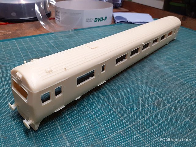
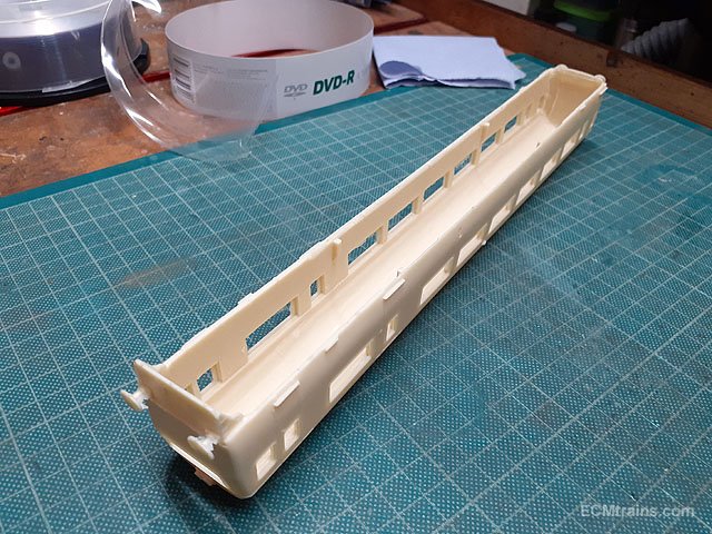
This is what you get from DC Kits;- The rest is up to yourself. Eoin
-
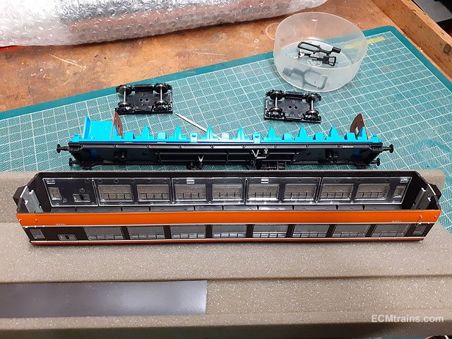
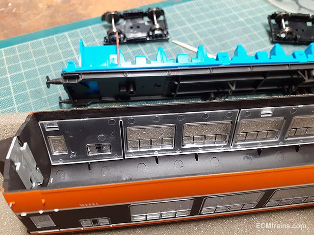
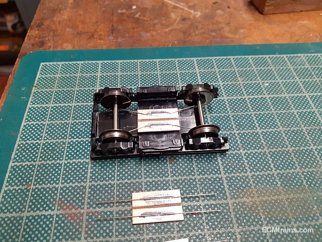
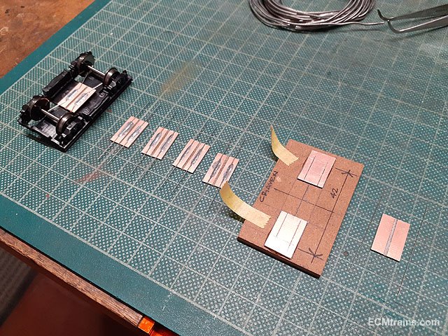
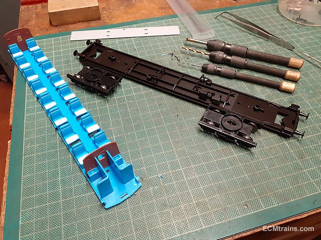
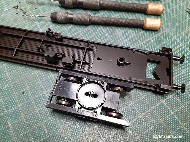
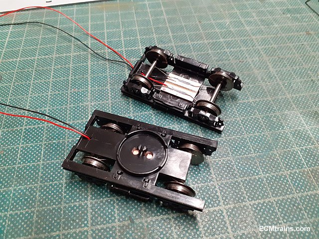
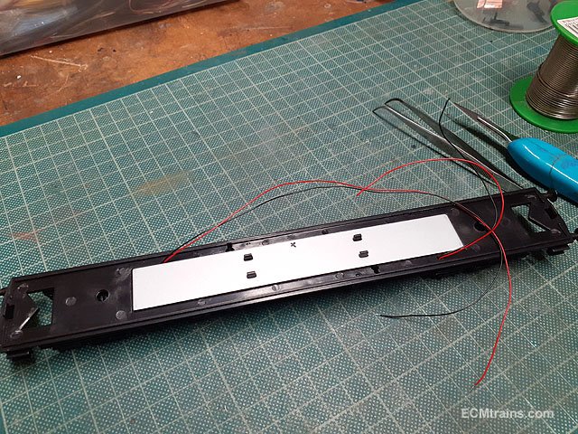
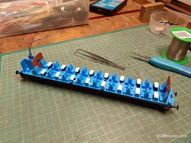
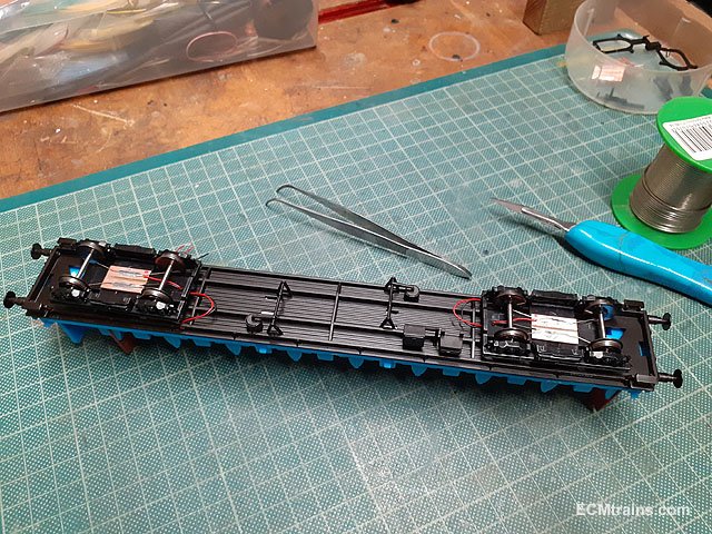
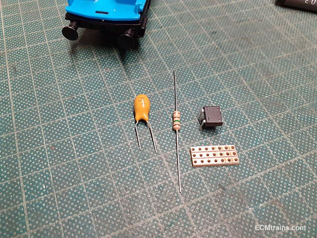
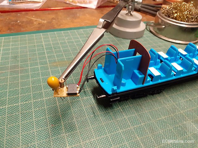
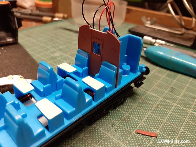
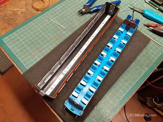
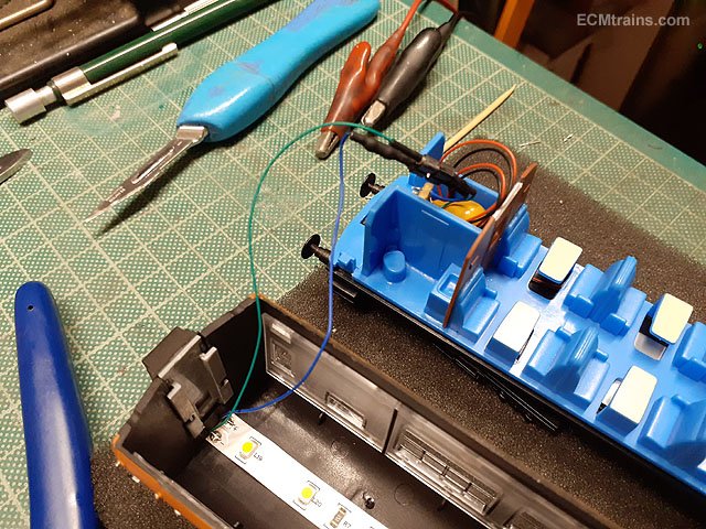
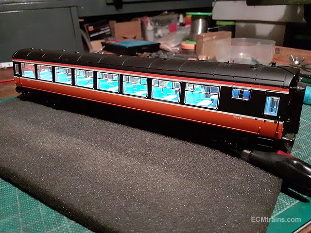
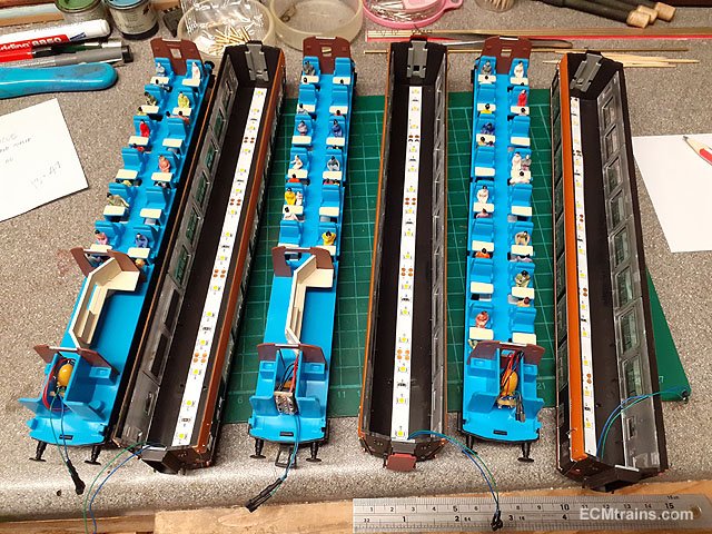
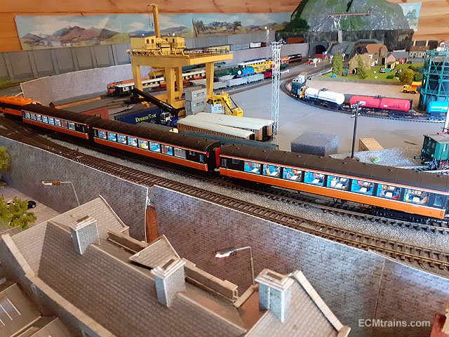
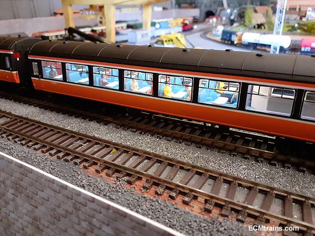
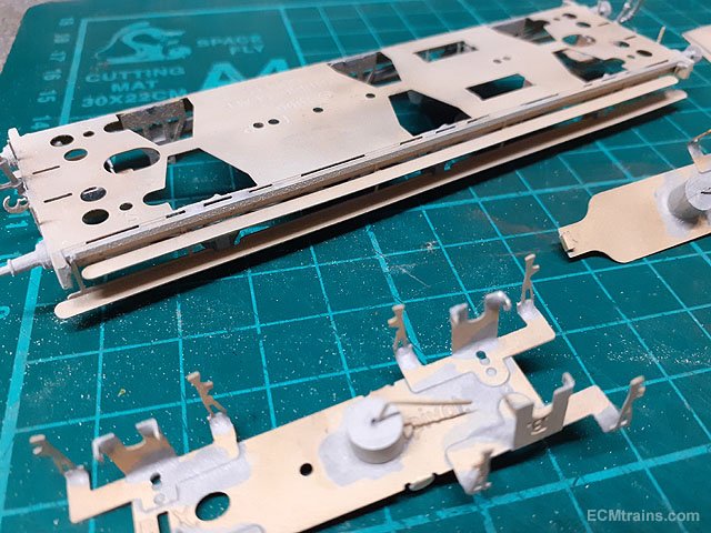
Installing LED strip DC coach lights in Cravens;- The coach body is held on by the floor side dents which slot into the glazing- 4 to each side, use cocktail sticks to disengage the dents and the body lifts off. The bogies pop off by rotating them 90 deg and levering one end up. Setting up the electrical pickup boards which are epoxied to the underside of the bogies, the jig is for soldering the .3mm NS wire to the boards. Holes are drilled in the bogies, the chassis and the floor between the toilets for the wiring. Bogies wired up. Chassis wired up. The wires run along the side of the weight. Floor on and the wiring threaded up through the hole in the floor at the toilets. Wires from the bogies have a generous loop to allow the bogie free rotation, before running up through the chassis. The electronics- stay alive capacitor, a resistor to bring down the LED strip brightness a bit, and a rectifier for polarity control. Electronics assembled. The tops of the coach dividers are trimmed a bit to allow for the LED strip to pass through. LED strip installed. The LED strip has a mini connector to the electronics so that the body can be disconnected. Testing. With lights installed one needs a few passengers! Eoin.
-
I use a 'Ceta Form' stripper from 'Electrical Merchants' if you have one of these outlets close by, it cost €16.00 approx. Here is a link to the type but this is a CK tool and a bit more expensive;- https://ie.farnell.com/ck-tools/431012/stripping-plier-vde-160mm/dp/1283264 Eoin
-
I reckon this would be the best starting point;- https://www.dckits-devideos.co.uk/index.php?route=product/product&product_id=973&search=mk3+dvt Eoin
-
until
-
The June Fair Date;-
-
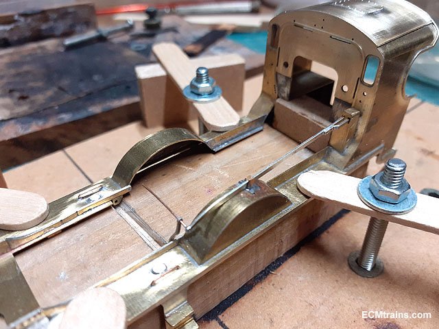
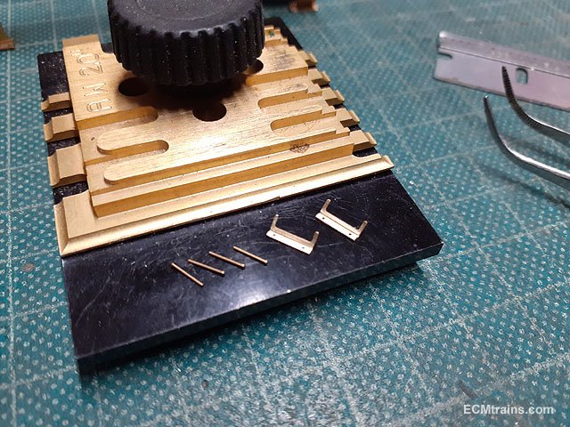
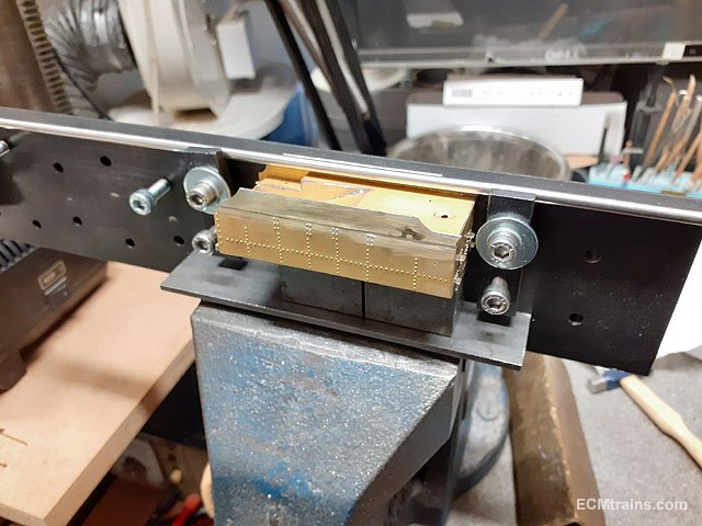
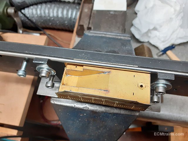
Yes, the jig has turned out to be very handy, it was originally made to hold the Worsley Works Class F cab while soldering, it is now used in all model building by changing the central mounting to suit the current job or jobs...... Eoin
-
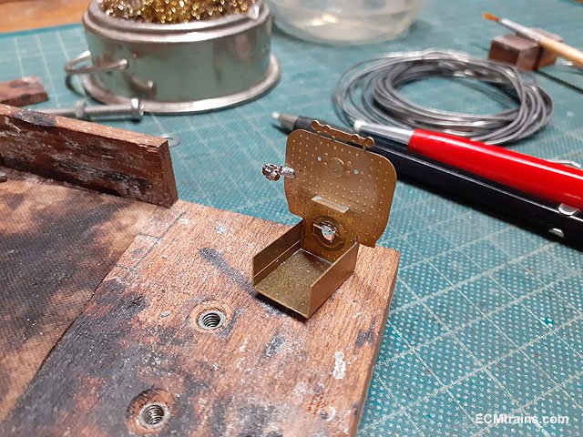
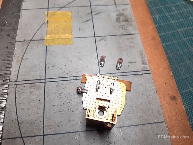
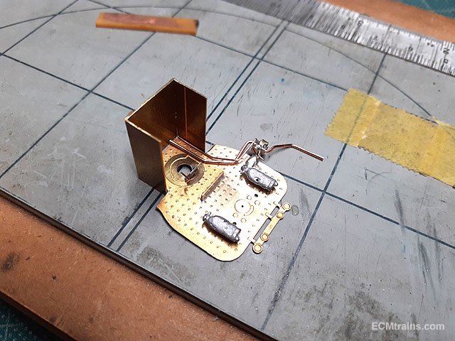
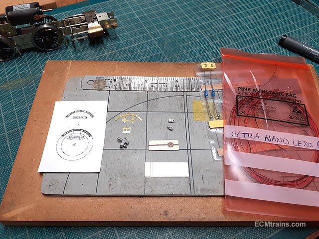
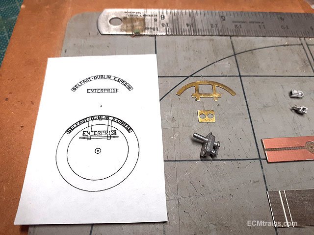
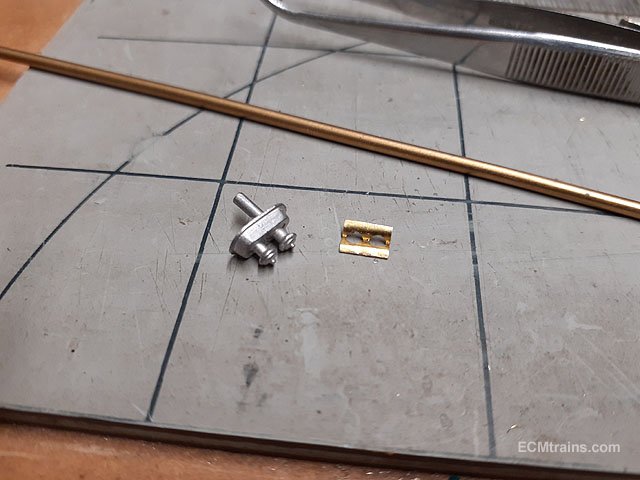
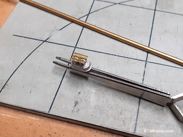
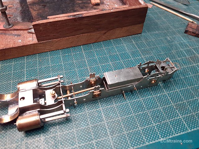
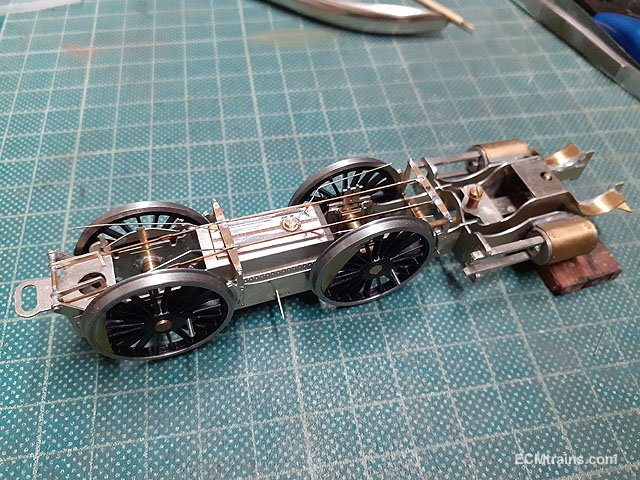
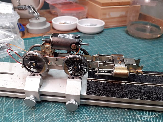
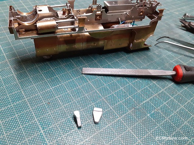
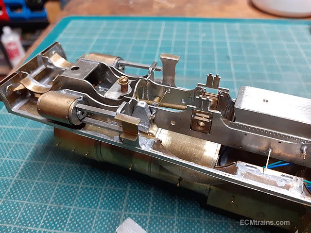
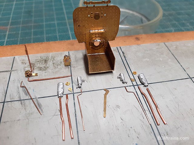
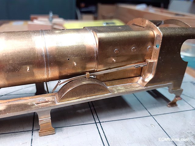
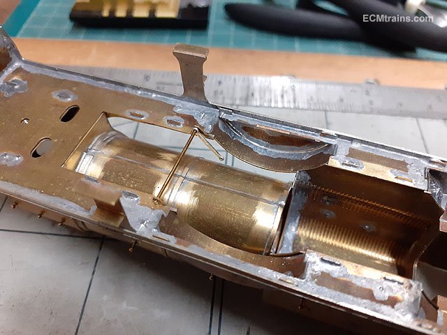
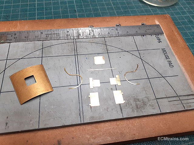
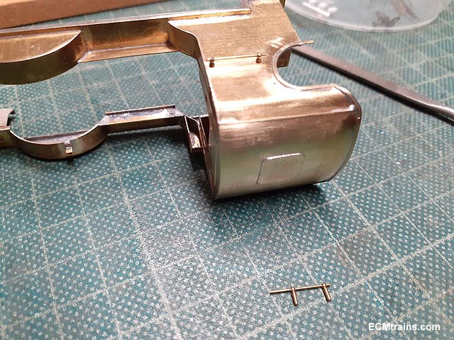
More bits on Merlin;- The vacuum ejector body and bracket soldered to the backhead. The combination injectors being epoxied onto the backhead with a bit of .8mm copper wire glued on the back to allow the later pipes to fit in behind! With the injectors glued on the vacuum ejector pipe work is bent n sized in .8 & .6mm copper wire. The backhead is now ready for paint- the first part for painting!! The white nano leds for the head lamps have arrived, the electrical pickup board and ash pan are ready do go on, and the smoke box 'Enterprise' sign was cut out from .25mm brass. Close up of the sign, it's artwork for making the decal, and a safety valve steam deflector was cut from the .25mm brass sheet also- so the crew don't get electrocuted by the overhead lines! The deflector folded up over a 2mm brass rod. It will be epoxied onto the safety valve later. Th ash pan folded up and drilled to take a 12BA captive nut to hold the electrical pickup pcb board. The pan was soldered onto the chassis from the inside. The pcb board bolted on and the .3mm NS wire wipers soldered onto the pcb board. Wipers under test- after the motor and pickup board was wired up. It alive!! Next was the front sand boxes, these had to be filed on the side to get them to fit without fouling part of the footplate detail. One can see they just squeeze in front of the weigh shaft bracket on the footplate/running board. And the final bits for the chassis- the cylinder drain cock pipes in .3mm pb wire and actuator brackets. Test fitted after the pipes were soldered together and the bottom of the cylinders drilled out, these parts will go on after painting. The chassis is now complete and ready for painting. Testing the fit of the smokebox sign which hangs on the top lamp bracket and has tabs that go in behind the smokebox door rail, also working out the lamp fixing........?? .......testing the new leds, which are white and no electrical shorts on the lamp bodies. Just a few more fittings to go onto the loco body and it will be ready for painting........ Eoin.
-
until
-
The date for next month's Fair = May 15, 2022;-
-
A PC has a 'print screen' button on the keyboard usually found at the right end of the function buttons on the top of the keyboard, the full screen is captured to the paste buffer, which can then be pasted into a graphics program like photoshop, or any graphics program, cropping and adjustments can then be done there. Eoin
-
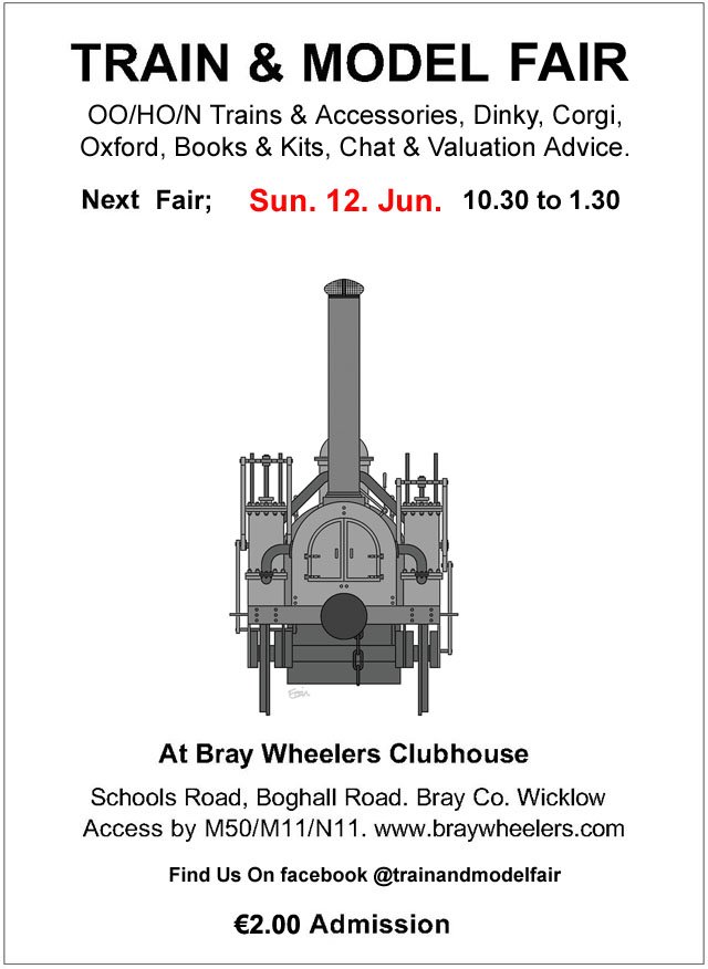
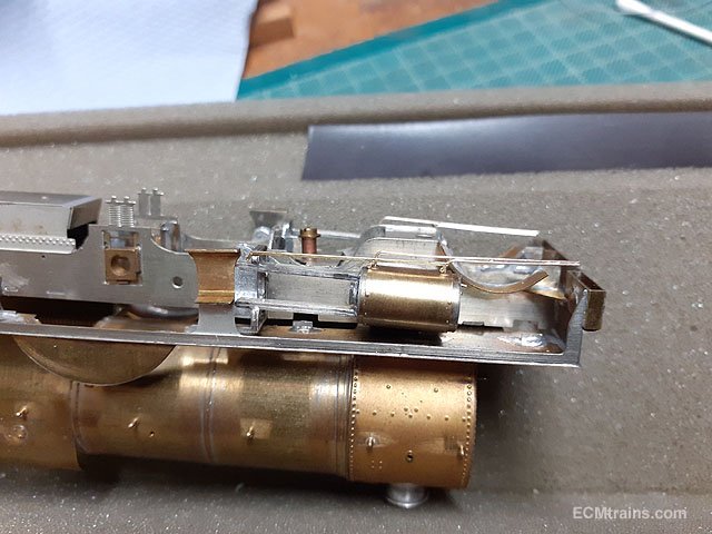
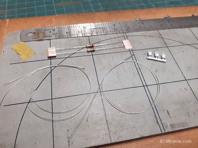
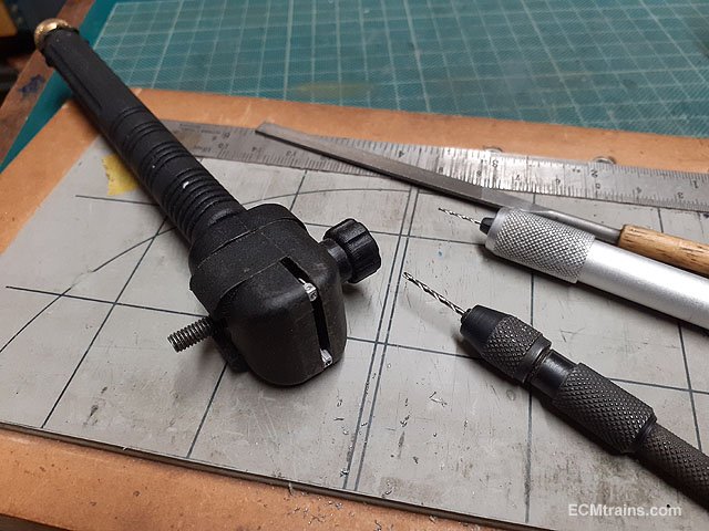
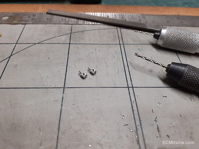
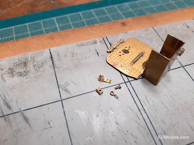
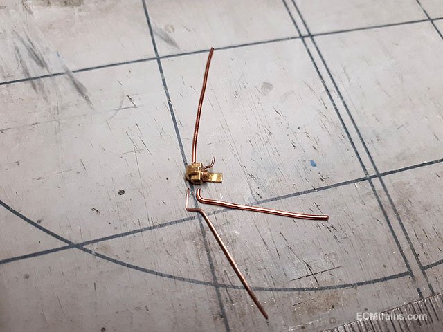
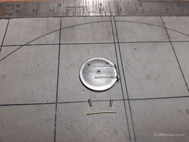
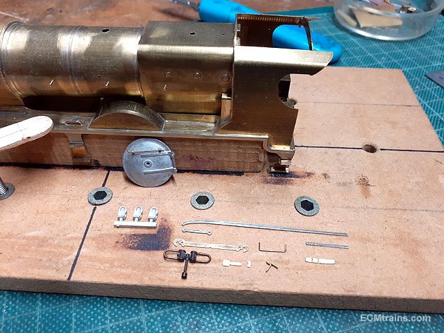
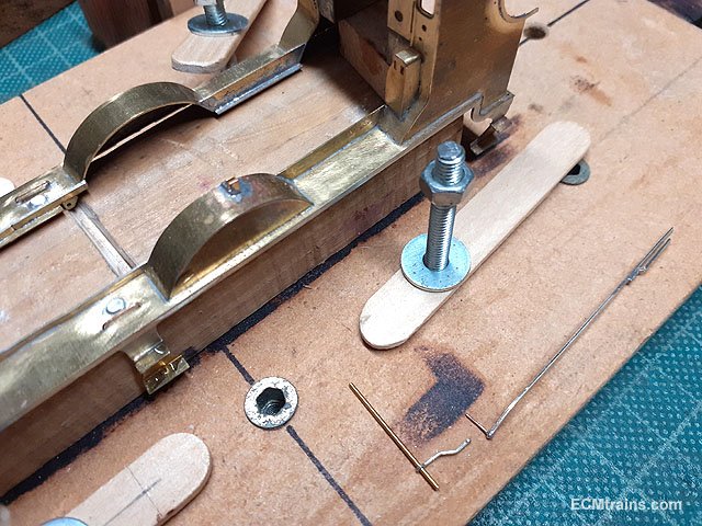
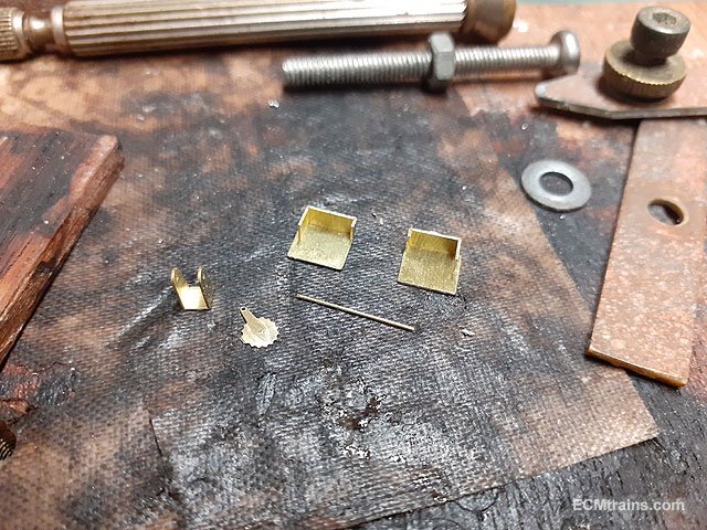
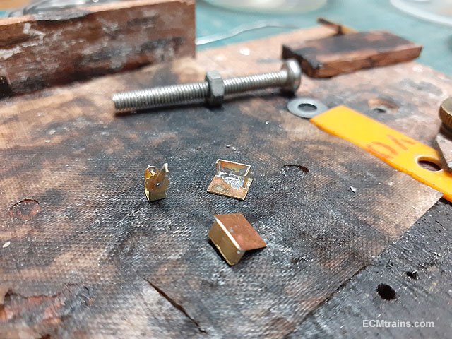
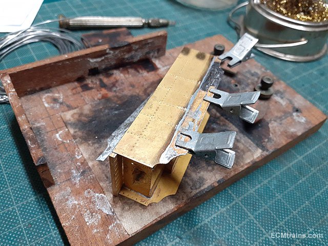
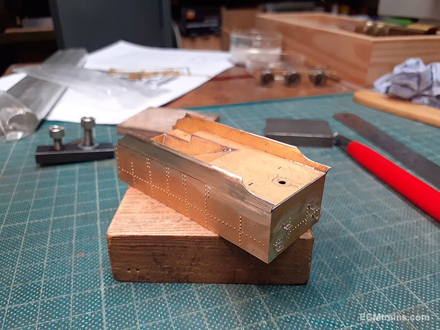
Onto the loco lights and cab detail stuff;- Warm white micro LEDs, 10k resistors and Springside white metal loco lamps. Drilling out the lamps with .8mm for the lens and 1.2mm to underside for fitting the LEDs in. Drilled. I Inserted an LED to test under power to find the LEDs are not warm white, but yellow! Also the 10k resistor needed to be upped to bring the LED intensity down. I settled on a 5 ohm resistor as the best, which is what's running the LED in the above photo. Warm white is now on order! The kit does not provide a vacuum ejector so I setup a few bits for one- from 1.5mm square brass box, a 14BA screw, .3mm pb wire bent up for the operating handle, and a brass strip to finish the body of the ejector and to fix the assembly to the backhead. Vacuum ejector and pipework setup for soldering. Combination injectors, water gauges, regulator handle, hand wheels, and pipe work prepared for the backhead. The pipes are .8mm & .4mm copper wire. The combination injectors will be fixed to the backhead now, the remainder will be fixed after the backhead is painted. Eoin
-

Wexford Model Railway Club - Easter Layout Exhibition - 17/18 April
murrayec replied to Noel's topic in What's On?
Here are a few photos of a Gauge O Class A built by Brendan Kelly of the MRSI;- Eoin
-
Wexford Model Railway Club - Easter Layout Exhibition - 17/18 April
murrayec replied to Noel's topic in What's On?
Here is a link to Nicholas Sunshine's video of the exhibition;-- 45 replies
-
- 10
-

-

-

-
Wexford Model Railway Club - Easter Layout Exhibition - 17/18 April
murrayec replied to Noel's topic in What's On?
Hi George, Every time I went to say hello to you & your Dad at the show I got distracted, then you had left, good to see you quys! Eoin -
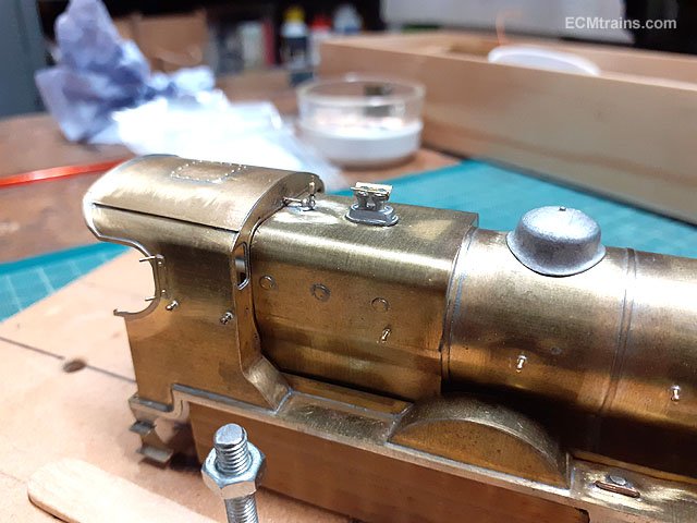
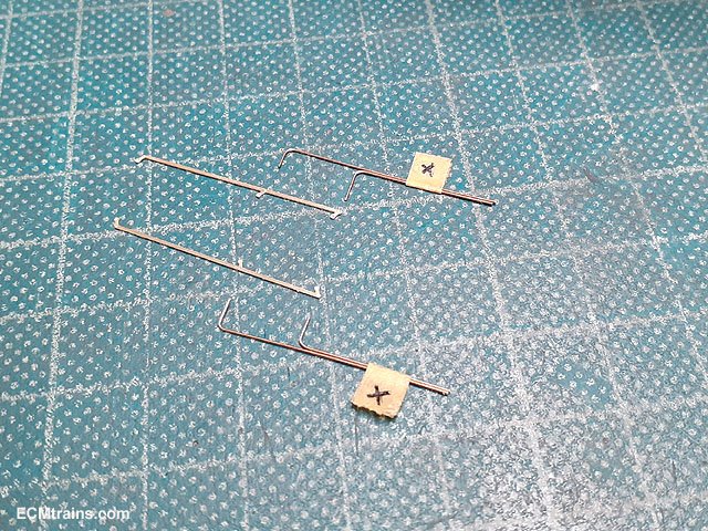
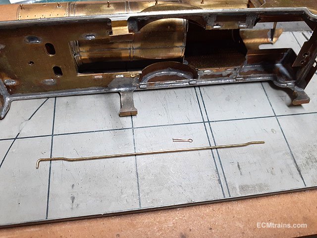
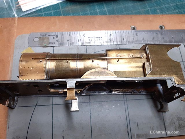
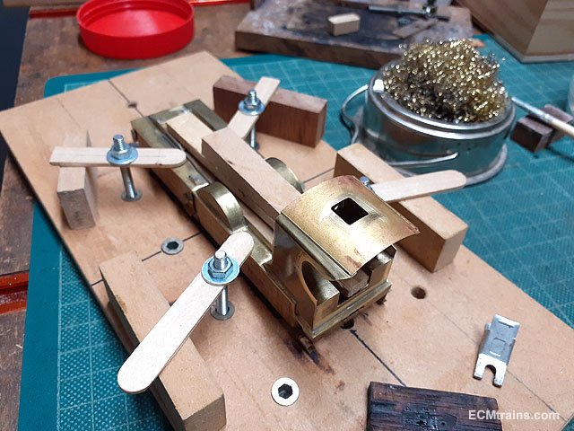
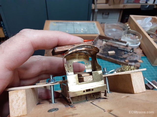
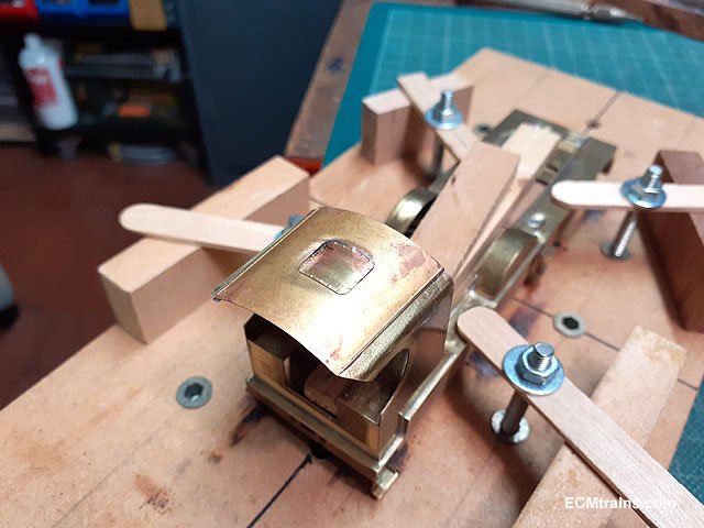
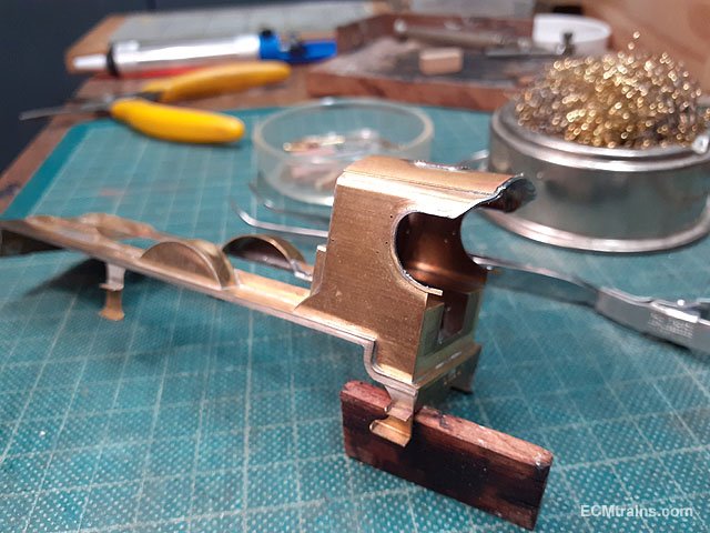
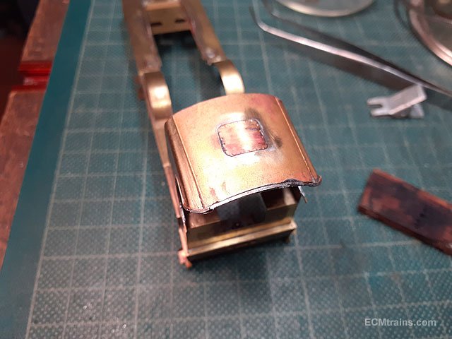
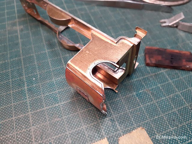
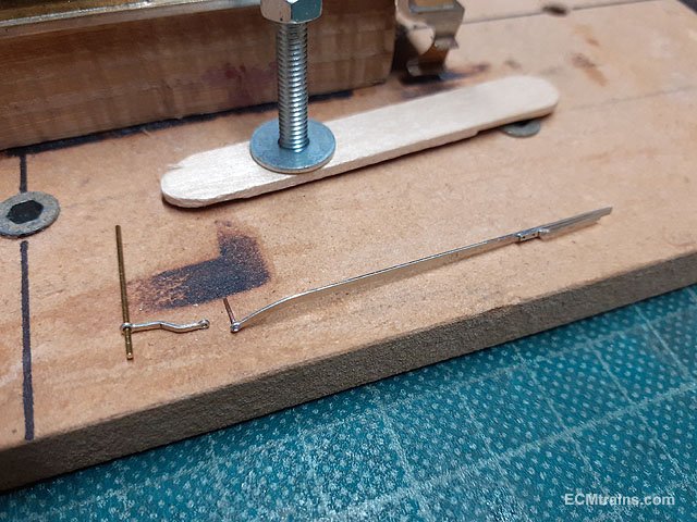
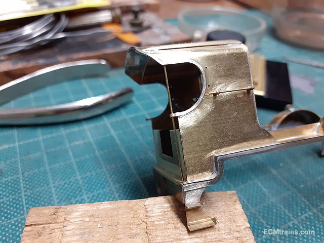
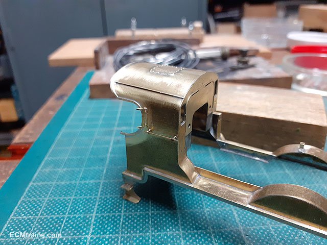
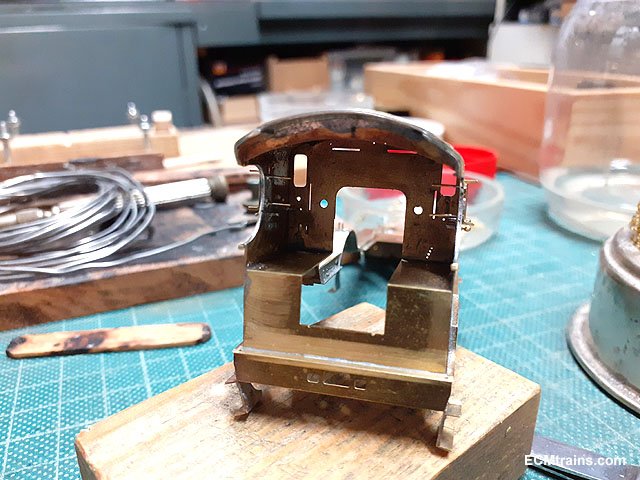
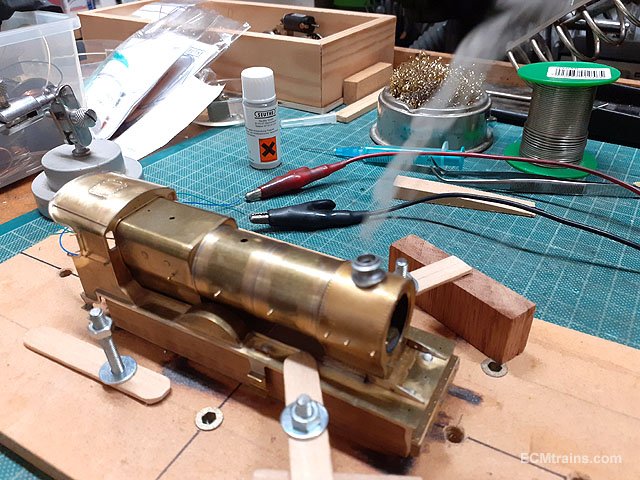
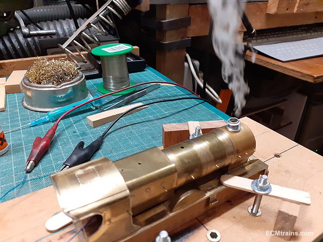
Back to the loco now, with some of the fiddly bits;- The steam ejector pipe bent up from .9mm brass wire with a .3mm pb split pin to bracket fix it to the boiler body. Test fitted, this will be painted separately and fitted after the boiler lining is done- I think, not decided yet! Smoke box door handrail being fitted. Some of the front end bits cleaned up and ready for test fitting, bending and soldering. The front footplate lights will follow later. Sizing up the bridle rod, reversing lever and splasher mounting bracket. The reversing lever is mounted across the footplate central space on a .7mm brass wire. Cab roof, roof hatch, cabside beading, cab seats and cab doors cleaned up and ready for folding soldering and fixing. Roof tacked on the cab and adjusted before soldering fully. The jig is very handy for doing this, using a bit of wood to hold down the roof and protect the fingers from the heat. Roof hatch cover soldered on. Cab sides and roof beading soldered on and needing a bit of a clean up. Bridle rod with the back fork bent up and soldered on, the front end has a .3mm pb wire soldered in the hole to hook up with the reversing lever. The lever is cranked outwards to meet the pin in the bridle rod end. Splasher bracket folded up and soldered in position, the splasher has etched marks to locate the brackets position. The bridle rod and reversing lever will be fitted after painting. Reversing stand and cab seats folded up ready for soldering. Soldered, the reversing bracket crankwheel has a .3mm hand crank soldered on. Cab side handrails being fitted after cleaning up the roof and beading. Cab side wind shields folded up, with .5mm brass rivets for mounting on the cab sides. Just before soldering the wind shields on I made up the cab end/roof rails with the cab side beading folded around the rails. Then the wind shields were soldered on from the inside. The rivets need cutting and filing flush inside the cab. Testing the smoke generator before the chimney and the smokebox door are glued on, once these fittings are on there is no access to the generator again- so checking it now........... First smoke...... Eoin.
-
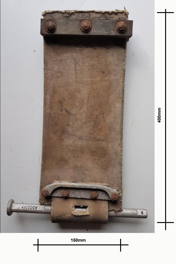
@fishplate7 Going by the chaps hand in the top image I'd say;- and the leather or canvas being 3mm thick?? Eoin
-
until
-
The April Fair date = Apr 10, 2022;-
-
GSWR/GSR/CIE Six-Wheeled Coaches - ECMbuild in Gauge OO
murrayec replied to murrayec's topic in ECM Model Trains
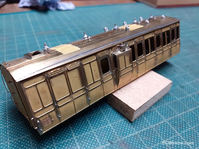
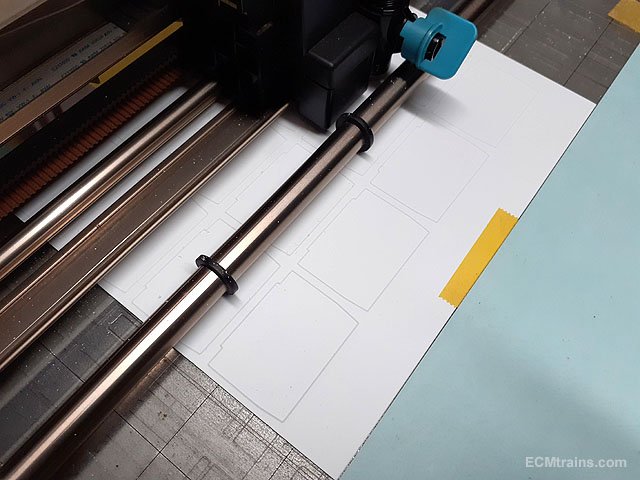
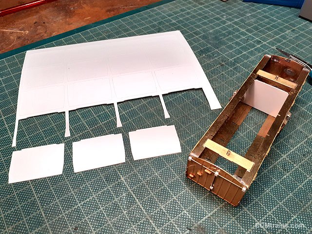
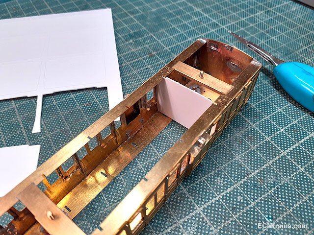
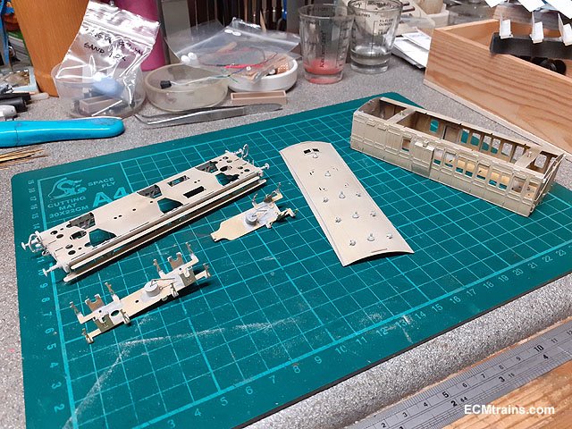
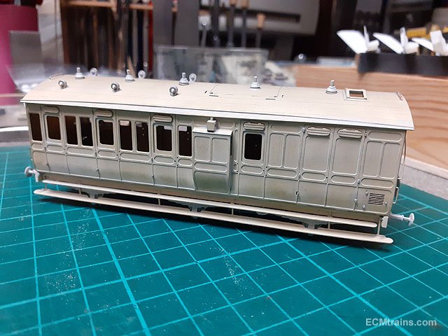
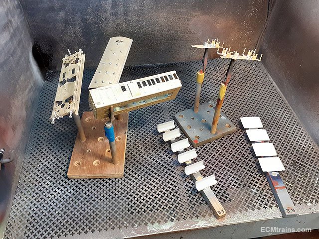
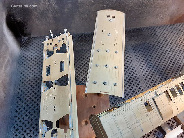
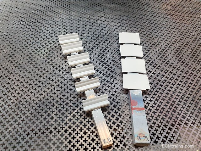
I have neglected to post photos on this thread for a while! So all the coaches are now assembled except for the last few parts described below. The final soldered brass parts gone on - lamps on the roof of the duckets. Cutting out the compartment partitions in .5mm styrene sheet. Test fitted, I'm going to paint these separately and then glue them in. This will help with the coach internal wall painting and fitting the glazing. Fresh from the mini sandblaster. Nice silky finish perfect for paint..... ......after a good wash though. All washed with warm water water n washing soda. Etch primer applied, a very light coat, just enough so that one can still see the brass under. Seats and partitions undercoated with grey enamel. Just shown one of the 4 coaches, getting through it and colour will be next....... Eoin.
-
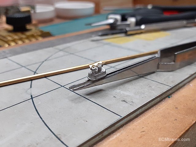
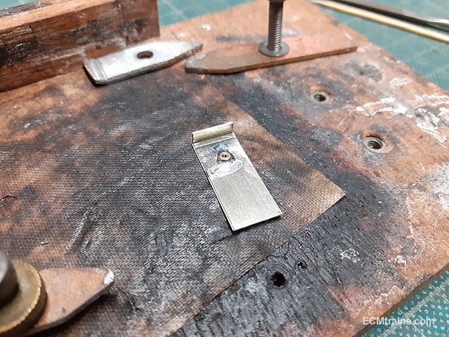
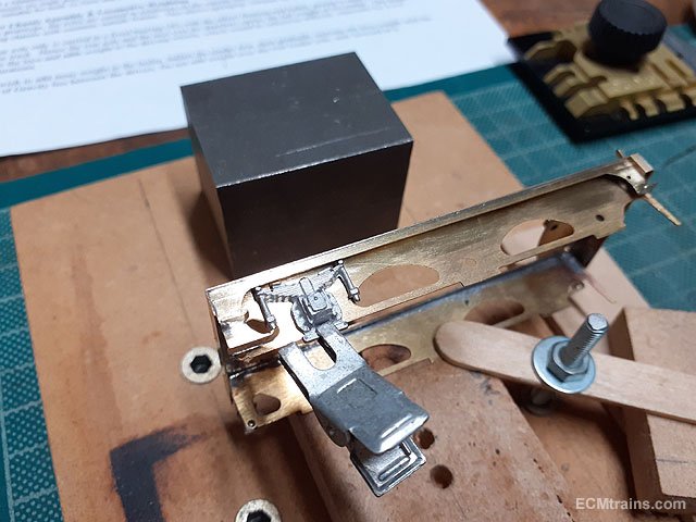
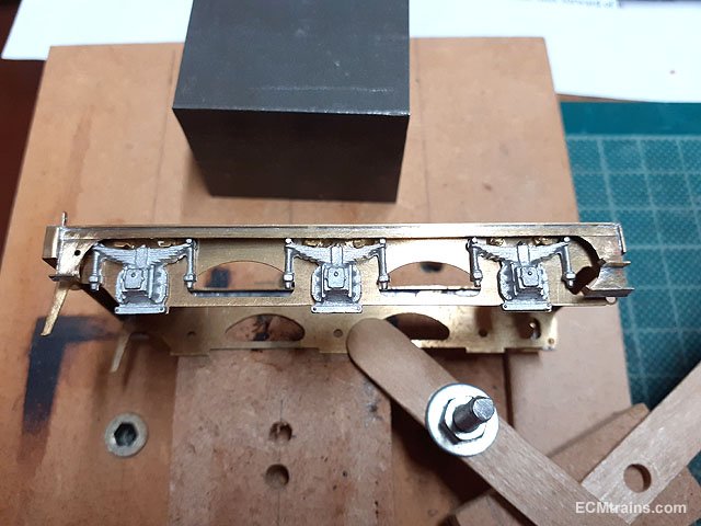
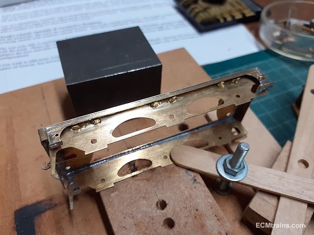
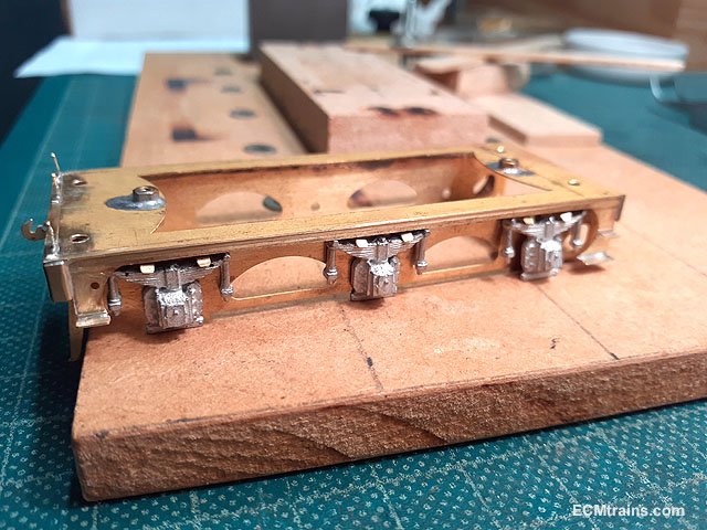
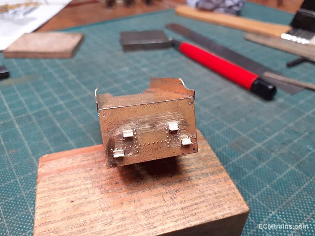
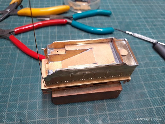
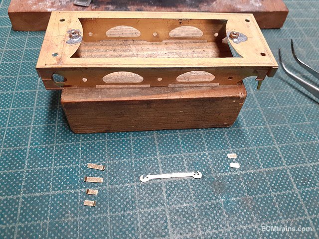
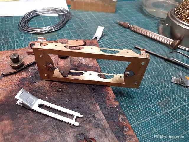
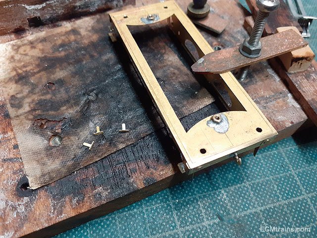
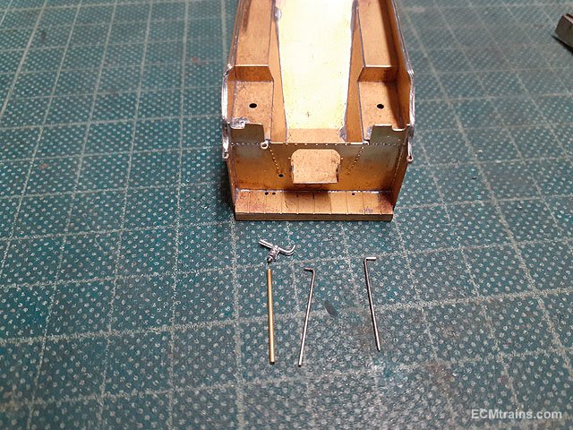
The tender spring clips/brackets- after studying a few photos of Merlin's tender I noticed the spring brackets are mounted above the springs with a gap between. The kit instructions suggest fitting the brackets directly on the springs, but it would look better and prototypical if a gap was provided! I decided to epoxy glue the brackets to the tender outer frames as soldering would be impossible, I used one of the springs with .4mm styrene bits stuck on to act as a jig for placing the brackets. The brackets were folded up and the outer ends were curved downwards with a round nosed plires. This is the jig set-up, its quite difficult to insert and position the brackets so the epoxy is going to be a bit messy. When the tender is painted and standing on the track one will never notice! One side done. Both sides done, the springs are propped up for this photo..... Eoin
-
Excellent, it's all excellent. Eoin
-
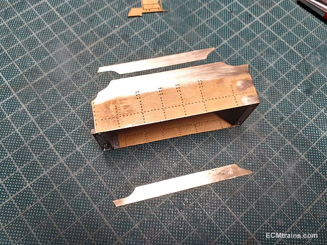
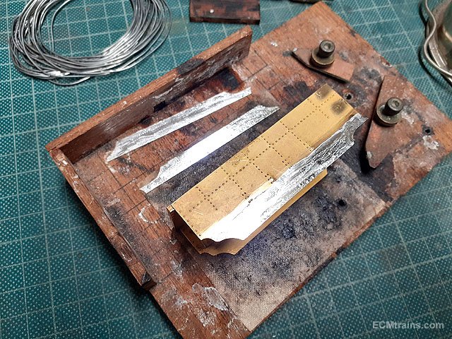
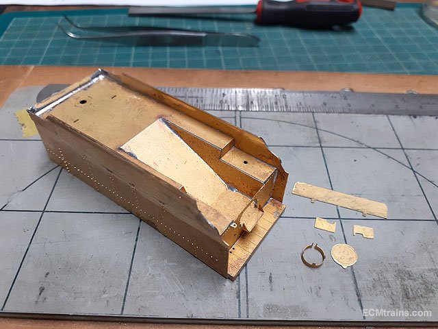
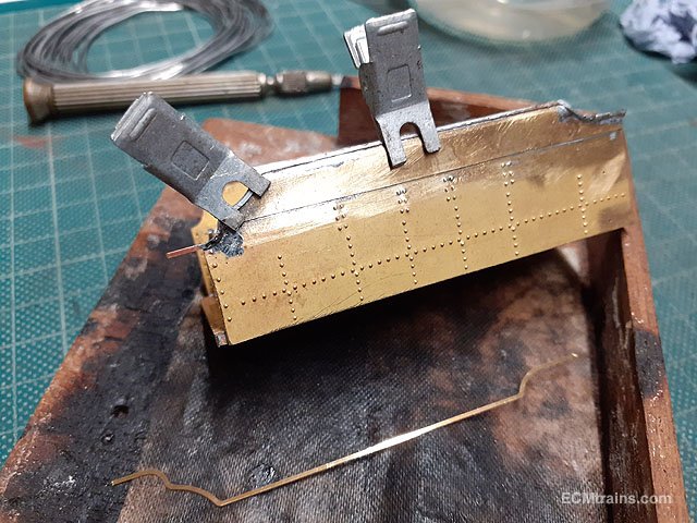
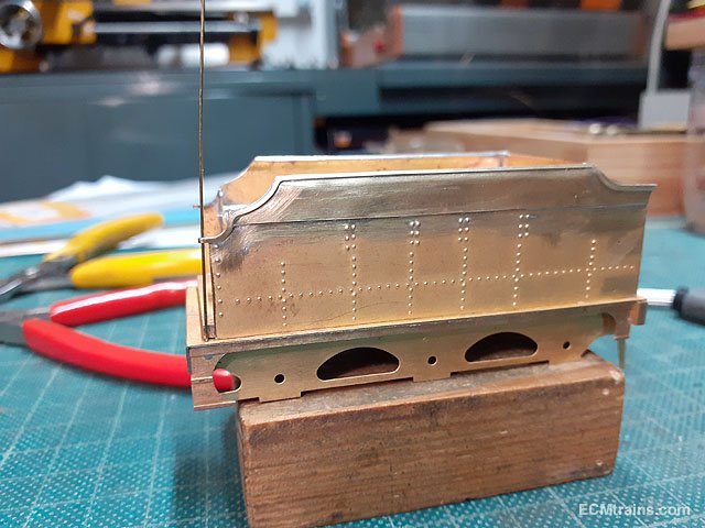
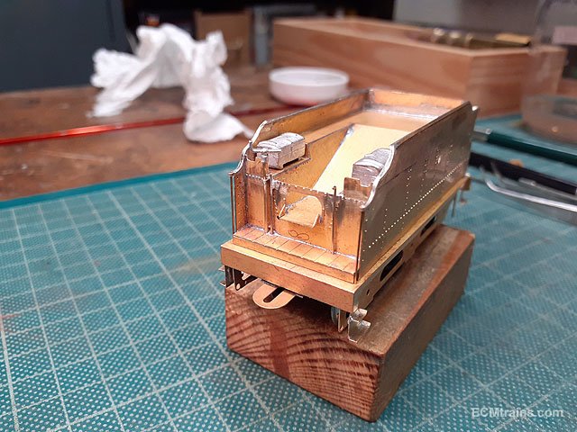
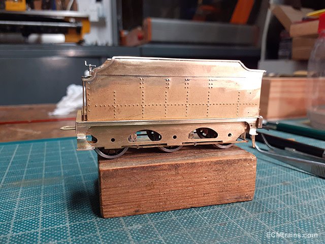
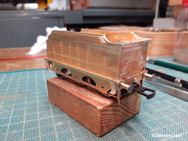
Continuing on with the Merlin tender;- The upper side laminate parts are prepared for sweat soldering on. Soldering is done with the help of Dinky clips to hold the laminate in place. With the soldering cleaned up its time to put the top curve in the sides. This is the clamping arrangement with a 6mm dia bar and packing under the tender body to stop it slipping down while the brass is burnished over the 6mm bar. Part way there, the burnishing was done with the ball end of that out of focus hammer on the bench in the background. Curve complete and cleaned up- the burnishing left a few marks which were sorted out with files and emery paper. The top back part was curved over the 6mm dia rod and soldered in place. Upper deck parts were prepared for soldering on. Edge beading to tender tops being soldered on. Beading after clean up and now preparing the end loop to hold the handrails. Water filler up-stand n cap, the coal sheet, and front tool box sheets soldered on. The coal sheet top corners had to be curved to fit the curved tender sides. Next are the side steps and draw hook. The steps are fiddly parts, with the aid of a Dinky clip to hold them the job worked OK except for burnt fingers! Dinkys are great because they are aluminium and the solder doesn't stick to them but they act as heat sinks- ouch! Rear lamp brackets bent up and ready for sweat soldering on. Hand brake and other handles prepared for fitting. The kit provides a white metal brake handle with a spigot for fixing, so I used a .8mm od brass tube for the riser with .5mm id to glue the handle into. The other rods are .4mm NS wire. Handles soldered on. That completes the tender assembly except for a few small items- the springs require clips to be soldered on, and the draw bar pin which I'm going to wait until the loco and tender are weighted and on the track to decide on the details...... Eoin