murrayec
-
Posts
2,718 -
Joined
-
Last visited
-
Days Won
70
Content Type
Profiles
Forums
Events
Gallery
Blogs
Store
Community Map
Everything posted by murrayec
-
A chap- Jay Kovac posted this on fb recently, its 1:13.7 scale live steam and runs on gas Stunning model. There is a video of it running on fb also;- Irish Garden Railways Eoin
- 30 replies
-
- 10
-

-

-
Is there a DCC spring wire in one of the problem points? this would keep the siding track live! Eoin
-
A bolt epoxy glued into the coach floor to extend down through the bogie with a nut under to hold the bogie on, some plastic card would need to be glued to the bogie top and bottom with a hole through for the bolt to pass, also you may need to adjust the coach downstand spigot with a file to get the height right. When the height is set use your favourite shade of nail varnish to lock the nut in place and allow a bit of play for the bogie to wobble side to side, nail varnish is better then threadlock as it open easier and wont break the epoxy holding the bolt in! Eoin
- 1 reply
-
- 6
-

-
-
I think I can claim poshness as I have four of them even tough no hooks Eoin
-
No hooks on mine! Eoin.
-
@Broithe yes they are very handy, and yes the plastic does not like sharp impact, I have four of them with two suffering the problem you have. Eoin
-
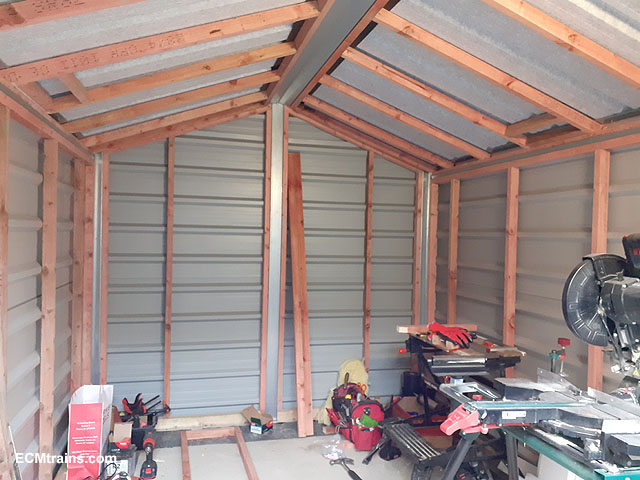
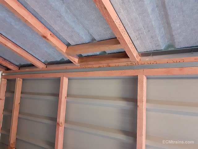
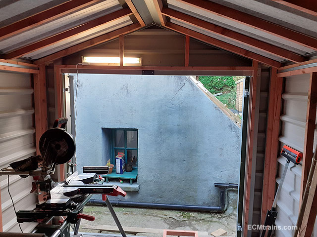
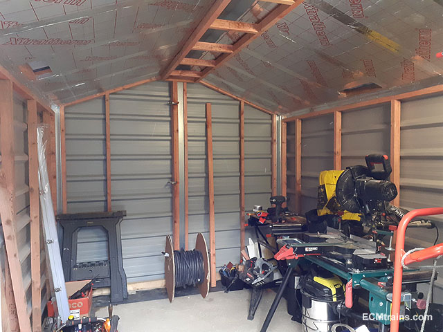
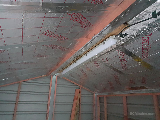
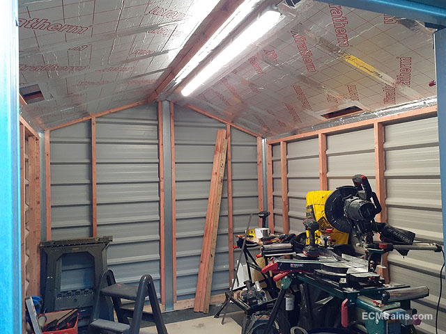
I got a bit done on the internals of the 'Lathe Shed' 50x35mm treated timber studs installed. The shed roof steel sheets were raised up with 10mm thick plastic washers at the eaves! The grey material on the roof sheeting is a drainage sheet, it's stops condensation dripping off the ceiling, but because the sheets were screwed down to that steel eaves beam the water in the sheet drained onto the beam- this would cause the timber to rot over time. 50mm roof insulation installed, ridge pelmet test fitted to see where the light fitting would end up, height wise. Pelmet modified, fitted and insulation installed. Light! Eoin.

-
until
-
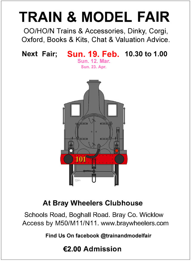
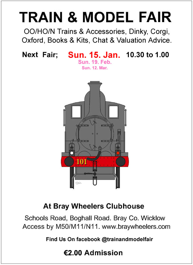
The February Fair Date;-
-
Mayner does a etch Fish Van Kit;- Eoin.
-
You'd have a better chance by contacting him through his website email, he does take time to respond...... Eoin.
-

Thinning cellulose spray paint for brushing
murrayec replied to Peter's question in Questions & Answers
As Robert says- the furry nature of the model will have it's touch up problems, I would go with the thickest paint (leave it in the palette to dry a bit after spraying) to cover the black runs. Thin paint from a brush might do the same thing- running into the black! Maskol fluid could be used on the edge of the black line to stop running if it happens. Cellulose or Universal thinners is for cellulose paint..... Eoin -
Looks real. Eoin
-
Aluminium/Silver/ Stainless Steel Effect
murrayec replied to dave182's question in Questions & Answers
Alclad is the best metal paints I reckon;- -
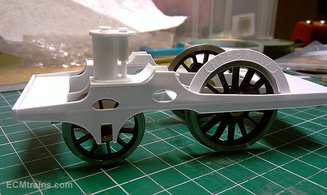
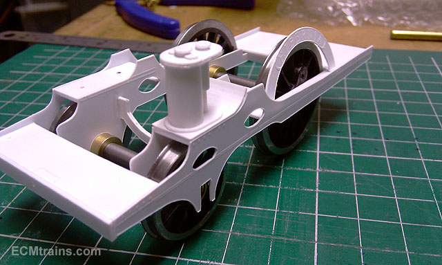
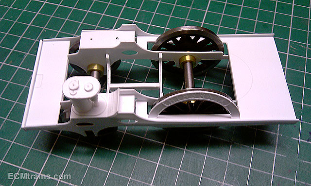
Yes, I do similar- making mock models, for layouts and buildings I use CAD more as I'm setting up the parts for say a building/buildings I can 3D them to get massing and fit ideas, then modify accordingly The same when building model locos CAD is very handy, but I also make up mock models in styrene to check fit- especially for scratch valve gear and motion rods. This is one example, 'Hibernia' the styrene model was constructed to work out how the brass chassis could be made, it was also used to work out the tolerances on the valve gear, drive rods and bellcranks. It was well worth doing as I found a number of difficulties to be sorted before starting the brass model;- Eoin
-
January Fair Date;- Happy New Year
-
Have you any information/detals on the 071 kits, and when they might be available? Eoin
-
I would be interested in the 071 and Duetz kits Eoin
-
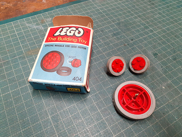
I wonder how many of us got a train set for Christmas!..........
murrayec replied to LARNE CABIN's topic in General Chat
I still have these;- Eoin
-
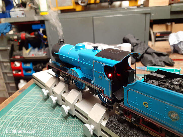
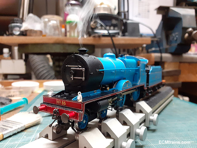
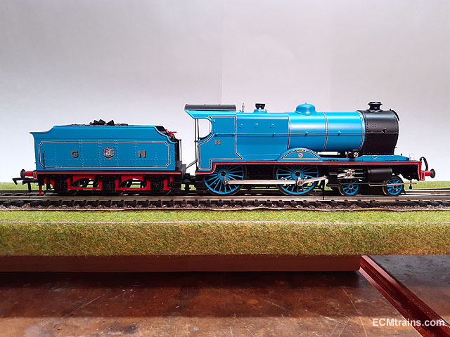
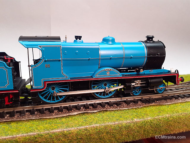
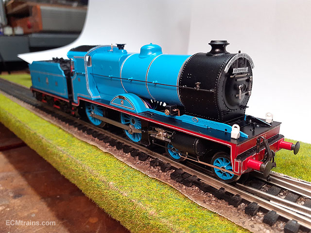
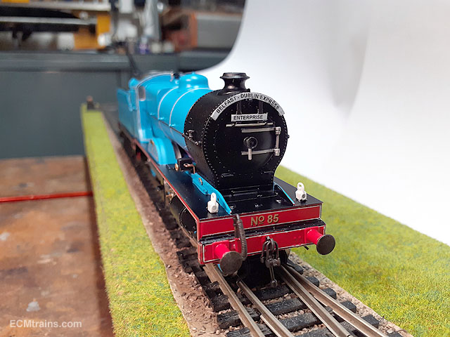
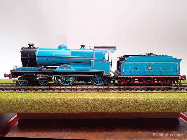
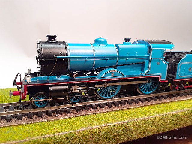
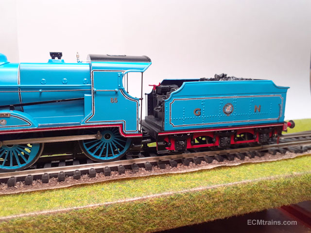
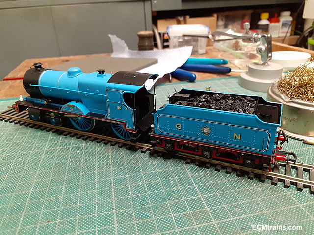
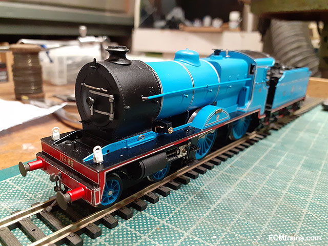
I'm happy to say- Merlin is finished;- Programming the chip to set up the smoke unit, the firebox light, and bring the headlamps down a bit. All worked OK so the final bits go on, and here is a final walk-round;- Done. I don't want to see another blue loco for a while......... Eoin.
-
So that's where Santa is hiding
-
Thanks all for the very kind comments and likes, it does help the brain immensely knowing that I'm not alone hacking away in my workshop...... Happy Christmas Eoin.
-
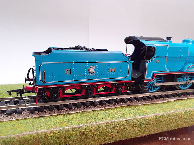
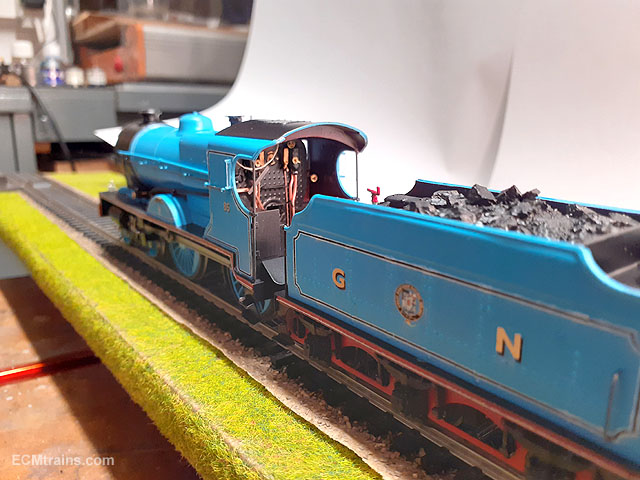
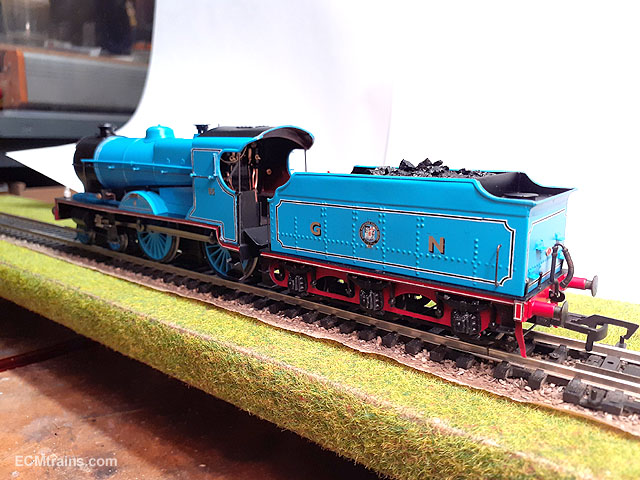
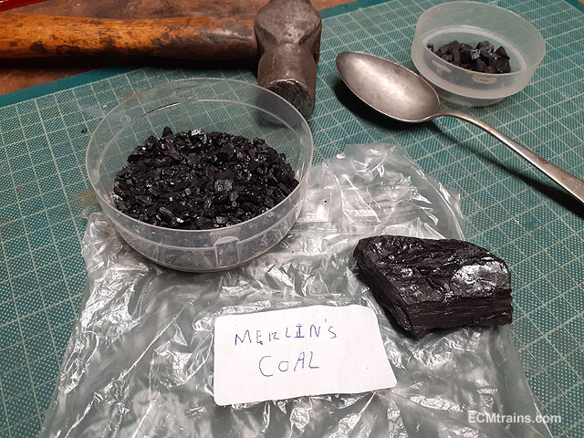
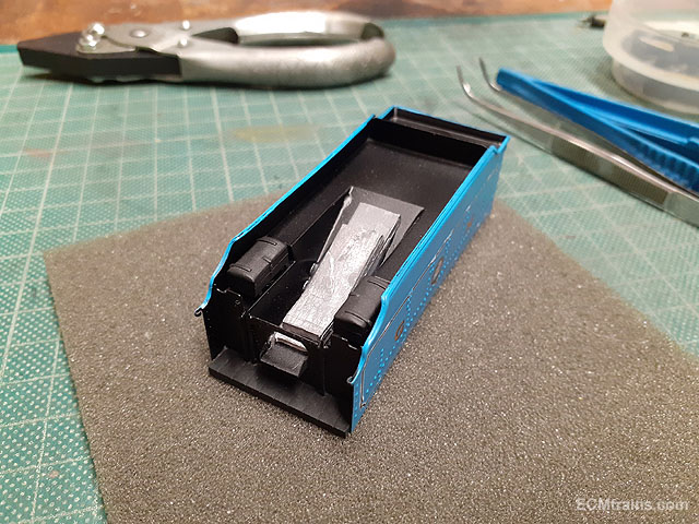
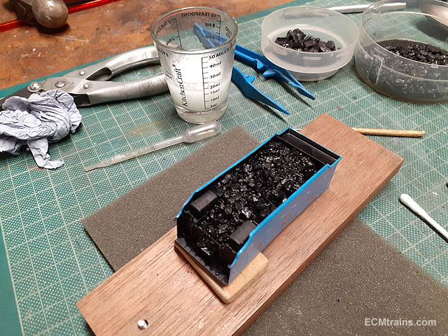
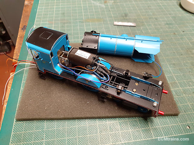
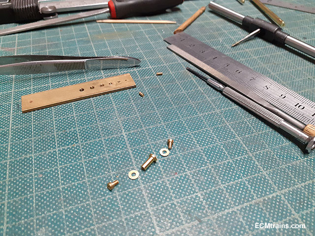
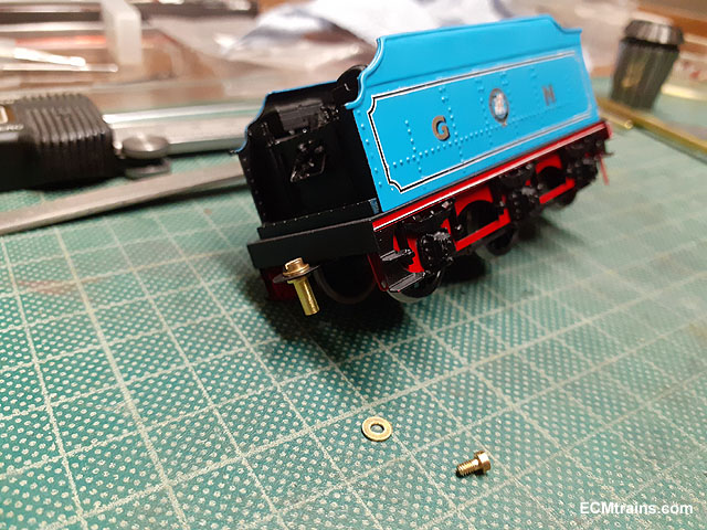
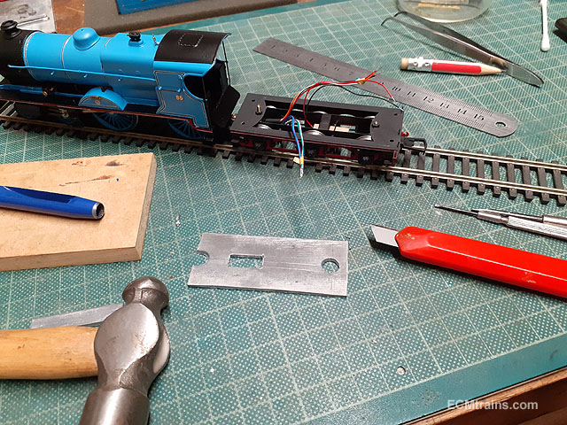
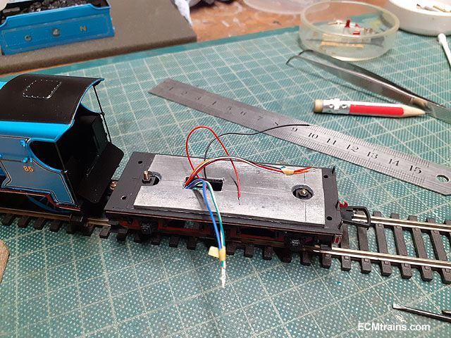
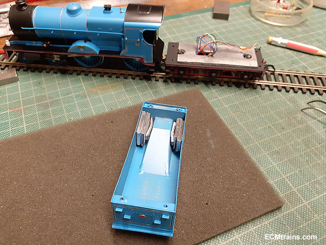
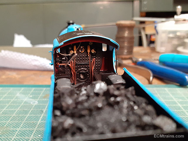
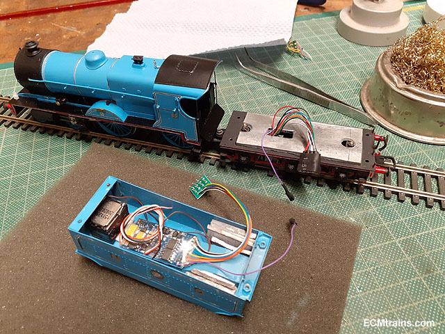
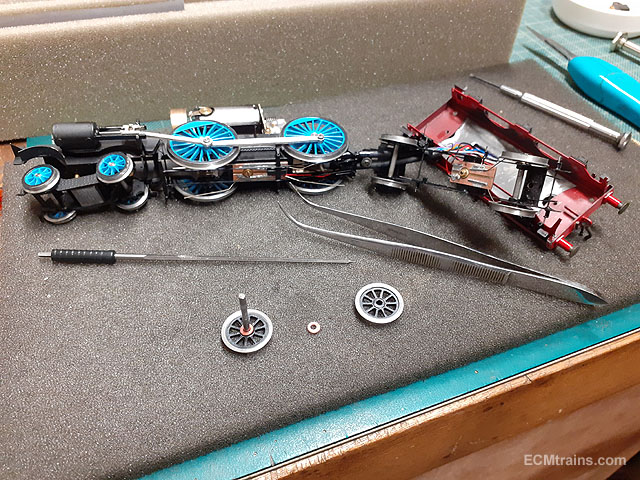
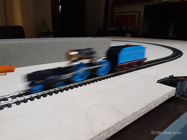
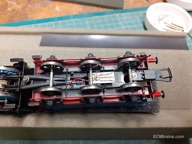
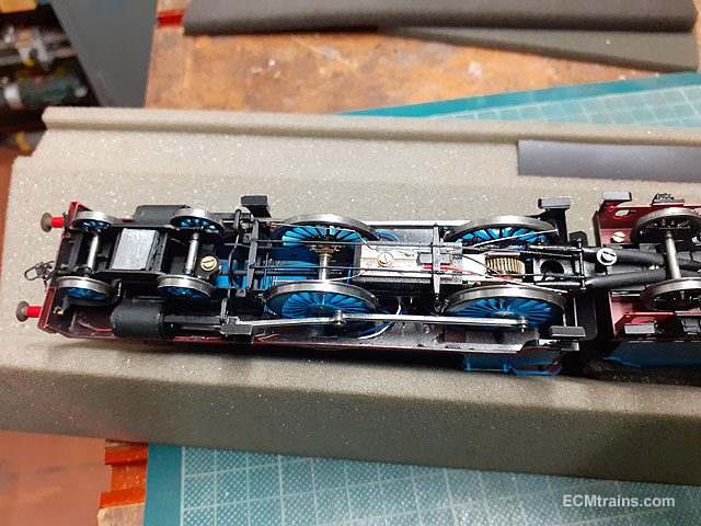
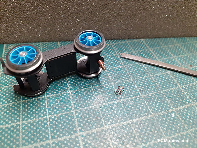
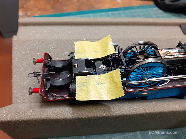
The final assembly and testing;- Preparing the coal for the tender, this is a bit of coal from Merlin's tender. Taking advantage of the coal space by adding a few bits of lead. The tool boxes have been epoxied on at the same time. Coal in and squirted with dilute PVA n some washing liquid to ease the tension. Installing the wiring loom from loco to tender. I turned up a tapped brass pin for the tender drag bar, these bits will be chemical blackened eventually. Test fitting, the tender will be permanently fixed and held with the second screw. Setting up the lead weights for the tender, the loco relies on the weight of the tender on the drag beam for maximum traction, so a lot of lead is the trick, with more weight to the front. And more in here! 8 pin socket wired up in the tender, the speaker and DCC sound chip installed with sticky pads. Ready for the first track test run! oops! nearly forgot to install the whistle pull cord! The first test run did not go well- electrical shorts everywhere and the model would only run on radius 3 track. To repair the shorts the model had to be dismantled- nerve racking as it was not easy to put it together in the first place, which caused a bit of paint/decal damage. The chassis and tender was test run without the loco body, which made things simpler. General views as to how the wiring was run from loco to tender. The front bogie had a small spring added to its fixing to the chassis- the suspension beam acts on the front of the bogie which caused the rear wheels to rise up off the track and not rotate. The spring did the trick. The bogie rear wheels would rub off the chassis on curves causing a short, not enough to trip the chip but it just looked wrong with sparks flying, so out with the file to shave the wheel arches back a bit. After 3 days of tweaking, dismantling the loco twice, eventually we have a constant running loco. A few minor issues to be resolved, final delicate parts to go on, paint/decal touch ups, and final lacquer........ I'll post up a better daylight video soon. Eoin.