murrayec
-
Posts
2,740 -
Joined
-
Last visited
-
Days Won
70
Content Type
Profiles
Forums
Events
Gallery
Blogs
Community Map
Everything posted by murrayec
-
@Dave Dawes Hi @WRENNEIRE is the man for Murphys 141s, 071s, 201s and are convertible to 21mm with a bit of jiggery-poke!, he's good for rolling stock also, IRM's new wagons are also convertible and I believe it's inbuilt in the forthcoming Class A loco- don't know about Murphy's forthcoming Class 121 loco yet As you will see in Galteemore's link you will have to make your own 21mm track or pay someone to do it Eoin
-
Thanks popeye I believe the crew will be doing that, among other things, I was not asked Eoin
-
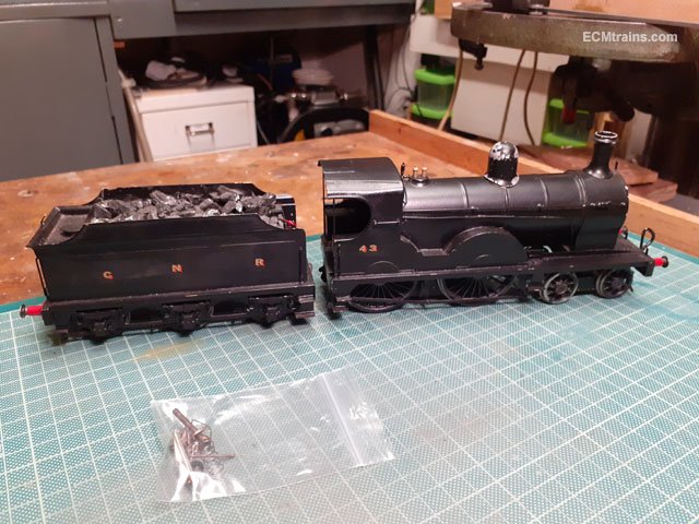
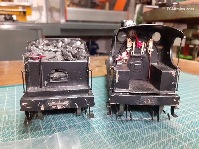
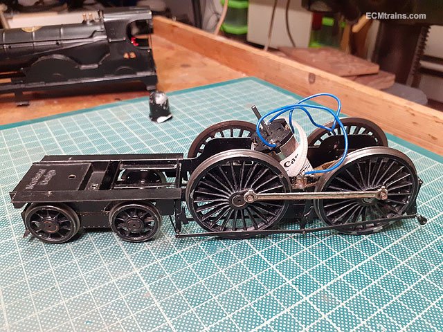
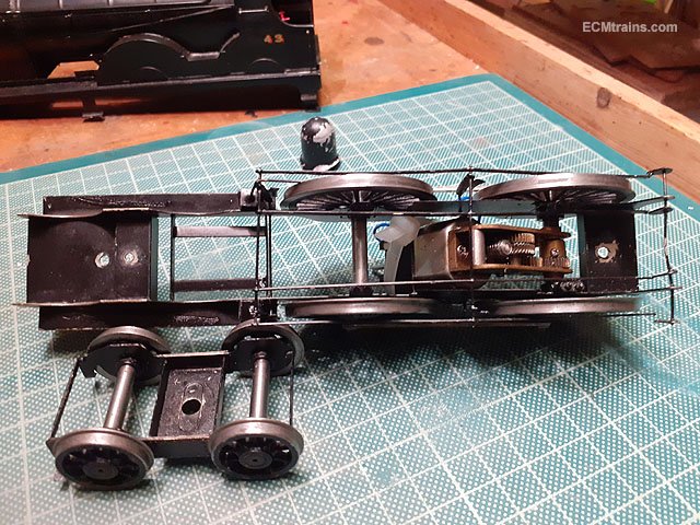
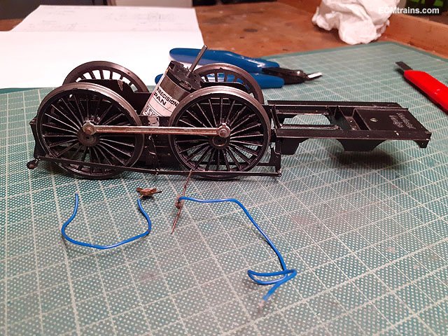
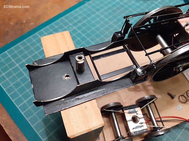
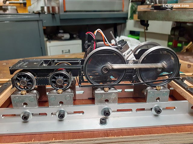
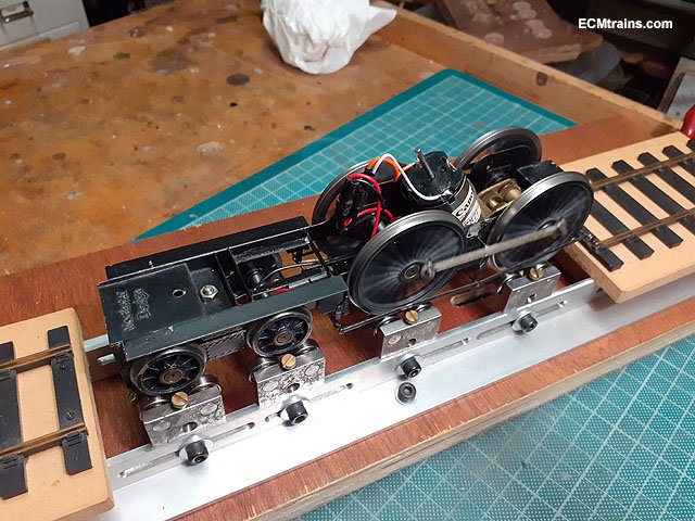
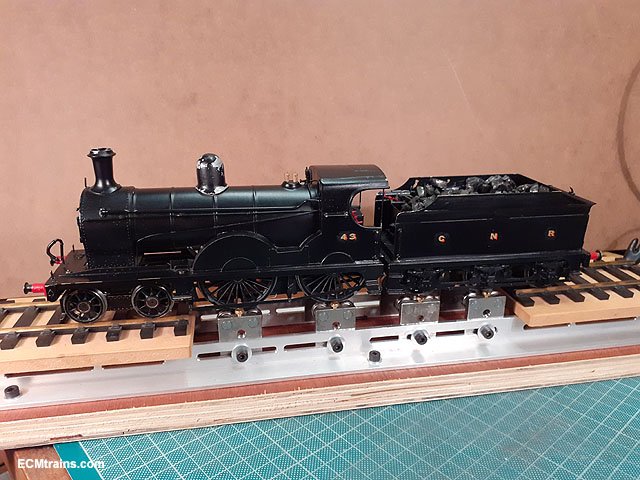
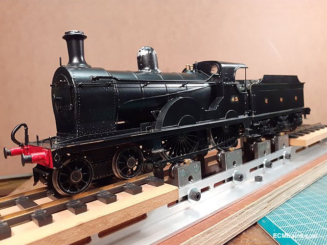
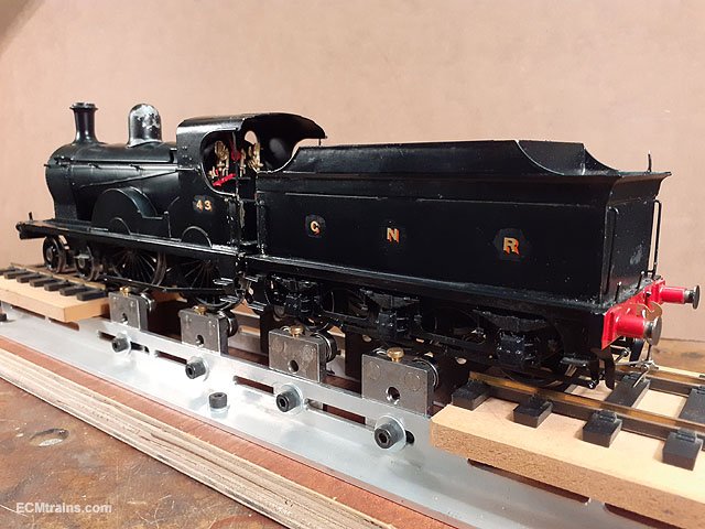
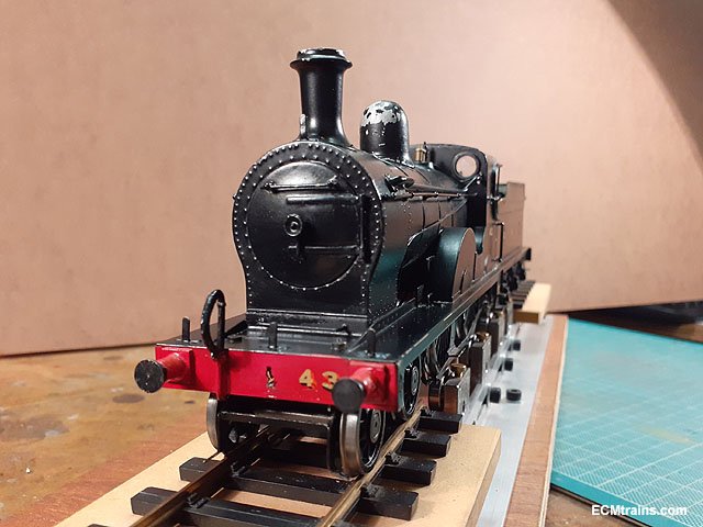
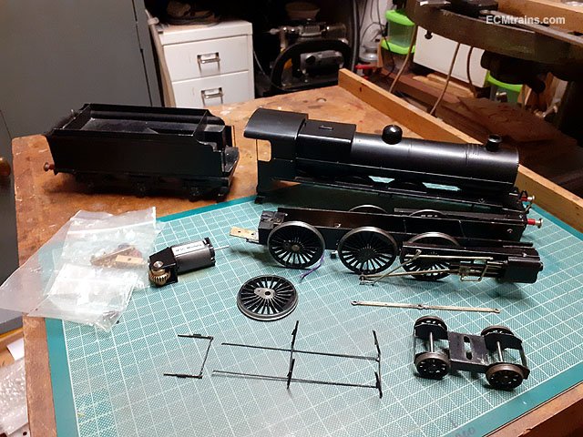
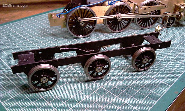
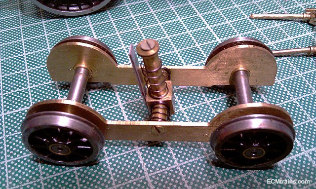
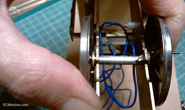
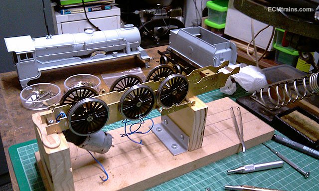
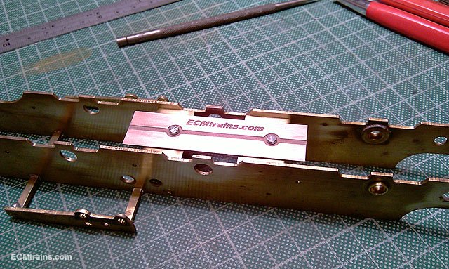
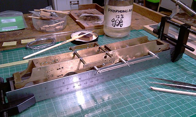
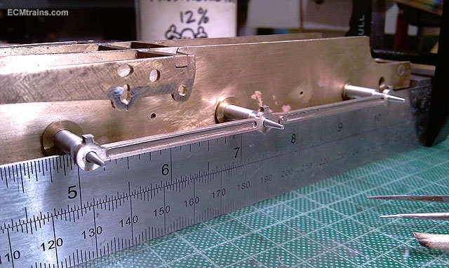
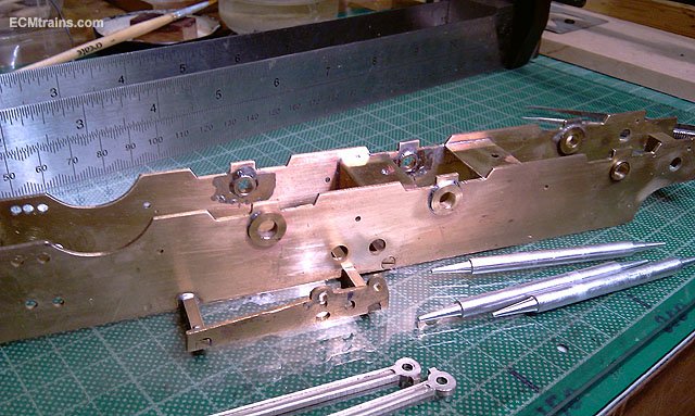
Recently on the bench was this GNRi Class 43 requiring driver wheel and bogie pick-ups, also a bit of a clean up. It's a 'Northstar Design' kit and quite well built, but the thin NS etched chassis frames and the lack of frame spacers down low allow quite a bit of flex. The 4 driving wheels do not sit level on the track! After taking a good look over it, a plan of action was worked out- a new bogie truck mounting system was added to the list. First I tackled the driver wheel pick-ups by removing the old system, these were squidged between the frames and the back of the wheels on a pcb board way thicker than needed and the wire stiff as a builders plank, one can see the mark on the frame between the wheels where these were mounted. The poor motor must have been using up all it's torque to counteract the pressure! A brass frame spacer was made up with captive nut soldered on and then soldered between the frames just in front of the motor. I used this spacer to try and get the four driver wheels level while soldering it in- it still titters a bit! A pcb board was cut out to fit to this spacer and travel down the sides of the gearbox to take the .45mm NS wire pick-ups. A few little repairs were done to the missing sander pipe and the back break rods were soldered to their corresponding brackets with little brass dress pins cut to size- Hickeys you know are a great source of modelling components! Then the wire pick-ups were bent up and soldered onto the pcb board, the wires had to rise up to get over the frames and under the break rodding without shorting, the electrical wires were also soldered on to the board. Next was to do the same with the bogie truck, but first I sized up a spigot to mount the bogie bolster to, turned on the lathe with a shoulder to pass through the bolster with a screw n washer to hold the bogie on. A bit of trial n error was needed until I got the shoulder depth right so the bogie wheels were just about level with the drivers with some play for the spring around the spigot to give a bit of suspension to the bogie truck! Then the chassis frame cut-outs for the wheels needed some filing to stop the wheels fouling the chassis and causing a short. Bogie mounted with its pcb board epoxied on and the NS wire pick-ups installed. Next was to give the bogie a bit of side play, so I milled a flat on both sides of the spigot and filed the truck bolster hole sides into a rectangle - slightly out of focus in the photo but it is rectangular. This arrangement gives ample side play for 1030mm radius curves. Bogie done, motor wired, and time to test run. I took six photos of the running chassis and afterwards when selecting from them for this post I noticed that the coupling rods always came out in approximately the same position. I gave the loco and tender bodies a bit of a clean up- the person that put on the decals was quite liberal with whatever solution they used and I felt it really interfered with the finish of the model- elbow-grease, buds, decal softener and loads of water did the trick. Done The crew will have to attend to a few small matters...... Eoin

-
@Galteemore I believe this is the very same model, the client is a member of the IGOG and I first saw the model at the meet mentioned in your attachement Eoin
-
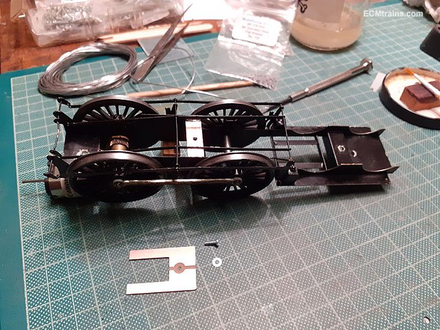
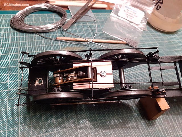
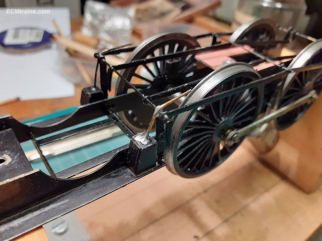
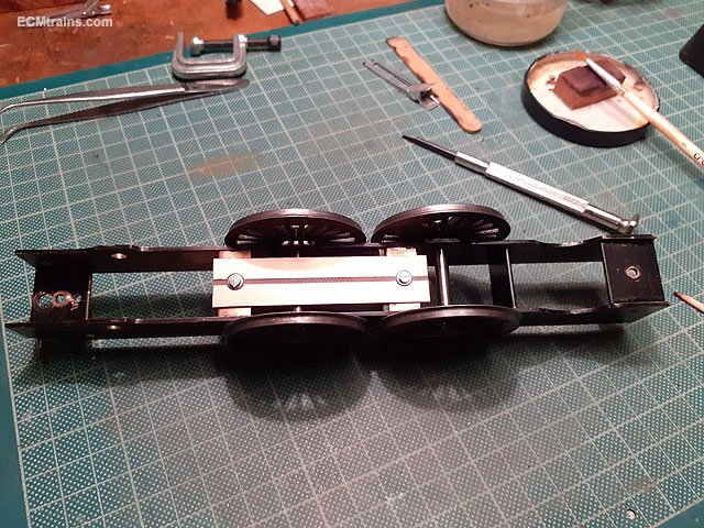
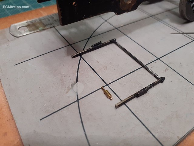
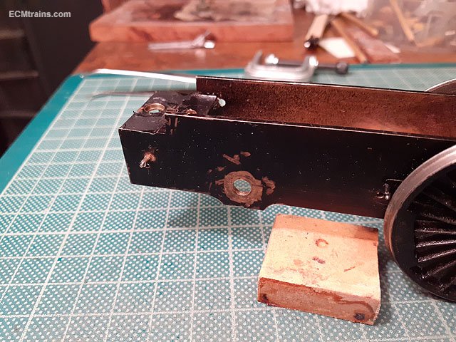
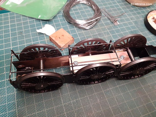
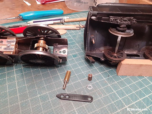
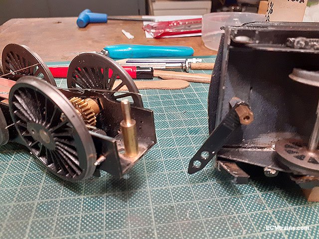
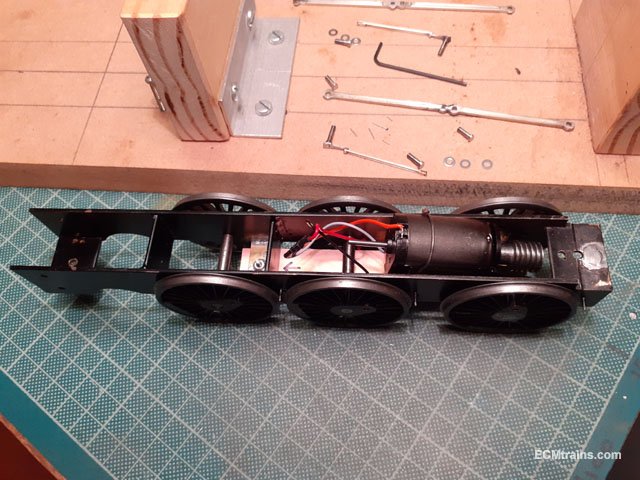
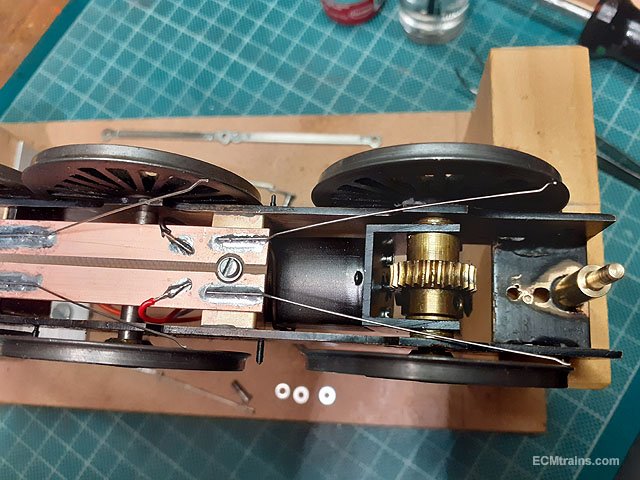
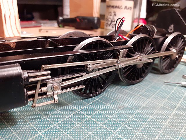
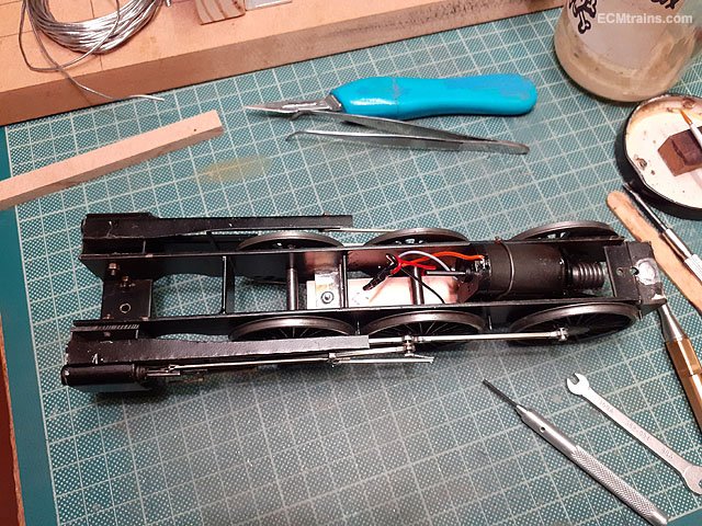
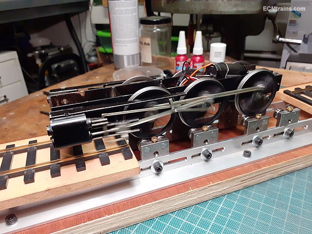
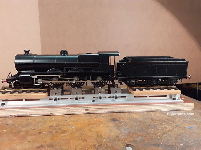
This lovely B2 model was on the bench recently, it's very nicely built but had a mishap and needs repairing, some upgrades to. Not sure of the kit make and the builder but I will follow up on that;- Motor & Gearbox replacement Valve gear rebuild Break gear repair Pick-up upgrade Tender draw bar assembly upgrade This is how the model came to the workshop. So first up was to start on the new pick-up system, a pcb board and brass angle mountings were prepared. The brackets were soldered in between the frames and M2 nuts soldered in to hold the pcb board. With the board setup I next repaired the break gear so I could install this assembly and make sure the wire pick-ups do not interfere when soldering them onto the pcb board. The break gear is the 'Sprung' on type, it fits onto the hanger shafts off the frames and is held in position by it's own springy force. The shafts are .9mm brass wire with sleeve over to hold the hangers out from the chassis- one of these was missing so a replacement was made and the break rodding was repaired. Break gear on and now the .45mm NS wire pick-ups are bent to shape Then soldered to the pcb board Wires to the motor were then soldered on. The pick-up wires will be bent and trimmed to the wheels when the motor is installed and running. The motor and gearbox now installed, a flat was milled on the axle to take the axle gear wheel grub screw and a couple of brass washers were installed between the gearbox and frames to limit side play and centre the wheels. Just before that I made the tender draw bar assembly- a ex 6mm brass spigot was turned up on the lathe for the loco end which was soldered into the chassis and a large cable tie was chopped n holes drilled for the draw-bar. Next was to install the valve gear, but first I added a bit of detail to the coupling rod knuckle join by drilling and inserting a 1mm steel rivet. Then the gear was cleaned up and installed. All on and waiting for the Loctite to set. Later a test run to see if all runs OK, and it's OK! Main work done I then installed the bogie truck and fitted the body Done. The loco needs a small bit of work to be done by it's crew, but it looks cool as it is. I really like this class loco, it's very sleek and looks the part for speed! but I believe they weren't very successfully, later they removed two cylinders and made a mess of the footplate lines when changing the valve gear and still they couldn't get it running right. This may be a sin but I think! I like this one more than the 800..... Eoin
-
You got to do it Eoin
-
Don't forget Nelson it's in Blackrock Collage this year On the main road to Dun Laoghaire at Booterstown, you can access up through Willow Park School or from Cross Avenue which is off Booterstown Avenue... Eoin
-
until
-
The October Date for the Train & Model Fair
-
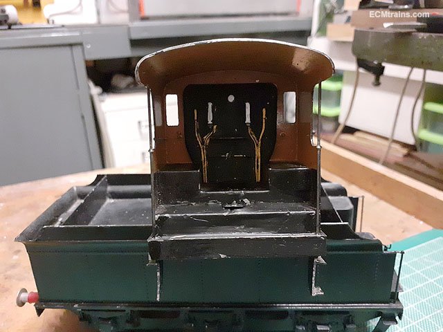
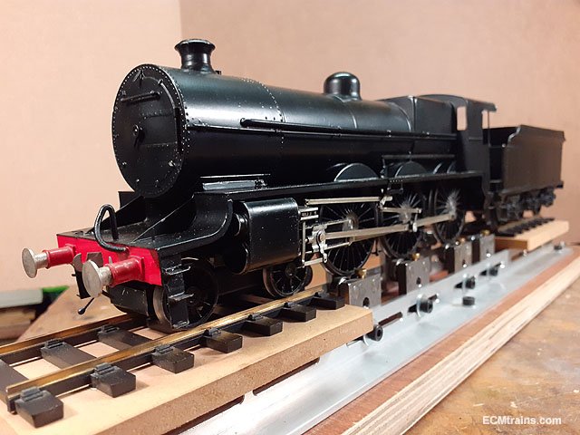
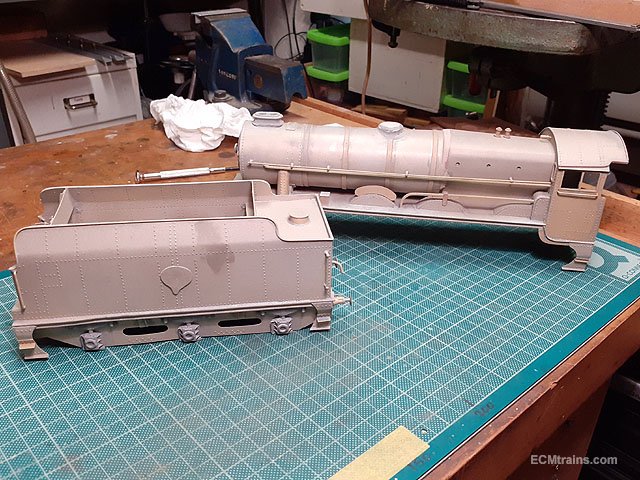
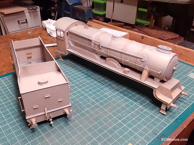
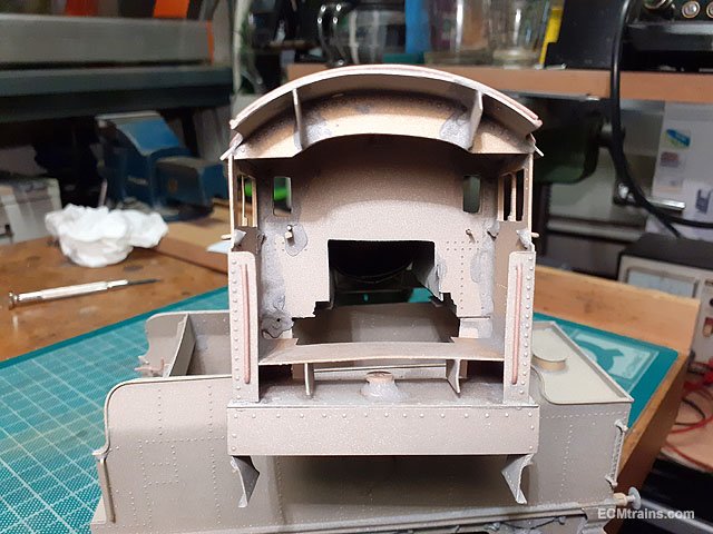
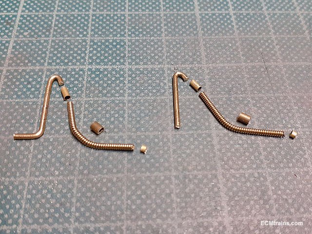
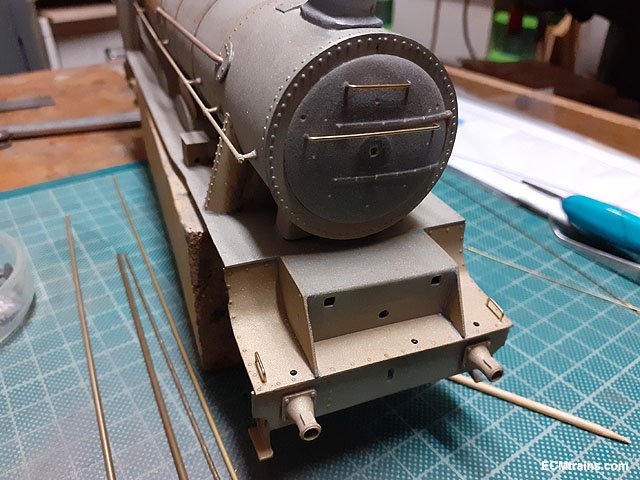
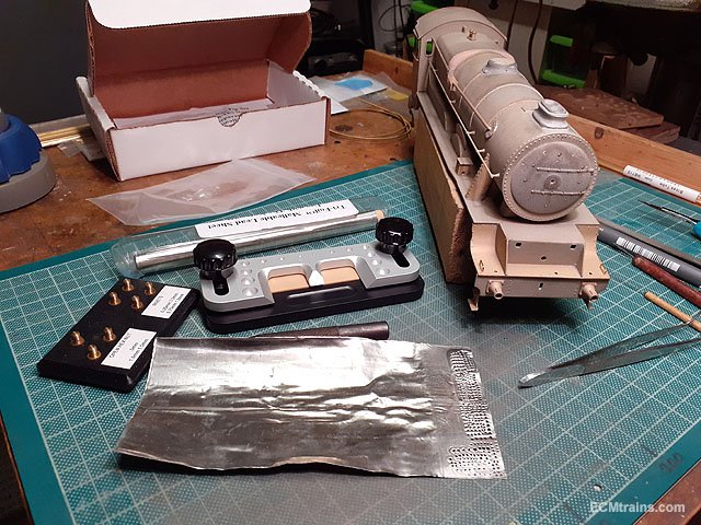
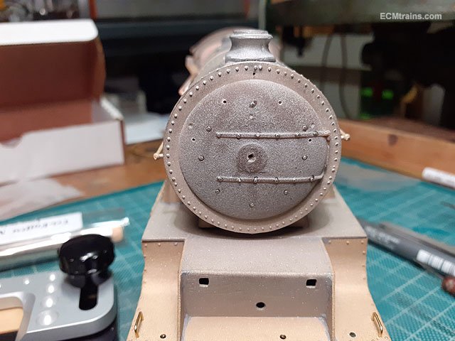
Thanks all for the great comments above. I intend to paint the chassis, wheels and body at the same time, so next up was to decide on the works to the body, after a good inspection I decided that some soldering and soldering clean-up was required and decided to add a little detail here and there so out to the sand blaster. All cleaned up. The cab will be getting a backhead but there is a gaping hole in here, the footplate is a bit wonky to, and a lot of residue solder everywhere- so another blast in this area is required, and I came up with an idea to fill the hole and fix the footplate- more on that later! After doing that I started on detailing the front end by drilling out the footplate and the smokebox door to take brass wire handrails, footplate lamps and some rivet detailing. Smokebox door rails and footplate steps handrails installed with .7mm brass wire. Smokebox door rivets going on with the help of the Nutter. And as one can see in the above photo the Smokebox door hinge is non existent! so came up with an idea for that using .5mm brass wire, two Gauge 00 handrail knobs and tiny brass tube strap end details to line up with the door straps. The NS frame was drilled for the knobs, these will have to be glued on as the door is resin cast and wont take soldering heat. Vac pipe parts for soldering up, done with brass wire, brass tubes and guitar strings. A bit of soldering and gluing to do...... Eoin
-
@MikeO We'll have to see how the printing goes! I get two or three A3 test prints done at a time, the printers are doing print runs in the thousands so my stuff only gets done when they have time. It's a bit like myself- I have so much on it's hard to get at this project. Eoin
-
Unbelievably the printer guy just rang! and has asked me to send my loco body cutting files and to prepare a drawing for the fold lines! They are trying out a new machine that can cut and score for folding the Xerox sheet- all fingers are now crossed! Eoin
- 55 replies
-
- 1
-

-
- 141 gauge n
- 141
- (and 1 more)
-
Hi Peter It's now the 'Scratched Record' thing'! The printer guy sorted the colour and printed the body sheets about 1 month ago, I was also getting HO scale body prints done at the same time on heavy paper and unfortunately he printed the Gauge N stuff on this heavy paper- impossible to fold at the N scale, and where I have outside cuts for folding the seam- its huge, white and to deep! I met with the printer last week and he is going to do the N again when he has the light paper in stock!! On the other side- I'm up to my eyes on other projects for people and finding it very hard to dedicate time to this project, it will be completed but when I'm not sure. Eoin
- 55 replies
-
- 1
-
-
- 141 gauge n
- 141
- (and 1 more)
-
@DART8118 oops!
-
The 141 is MIR Eoin
-
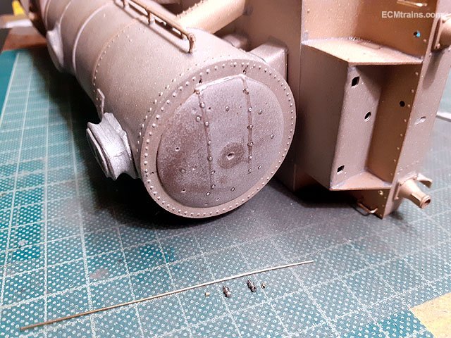
Borithe Is that the correct shade of grey? Eoin
-
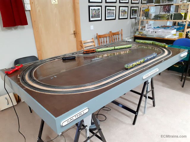
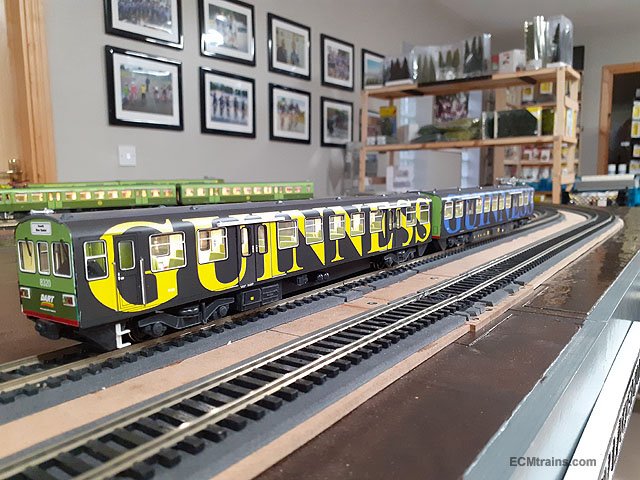
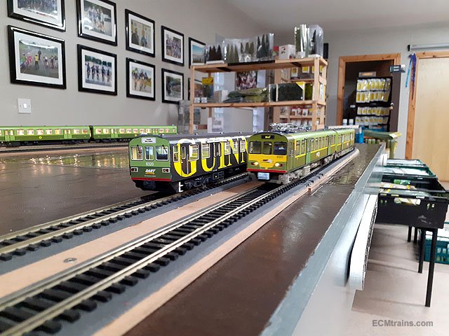
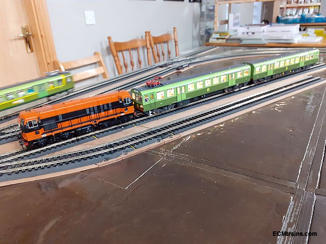
Some photos of the DARTs running on the new board and the Transition DART 8102 pulled by 143 for driver training. Eoin
-
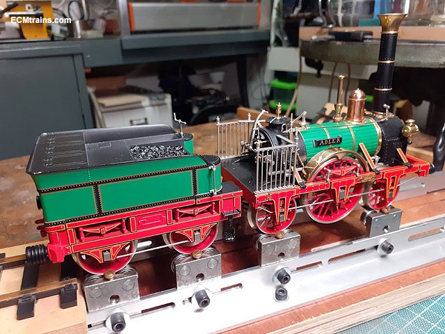
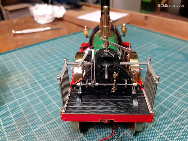
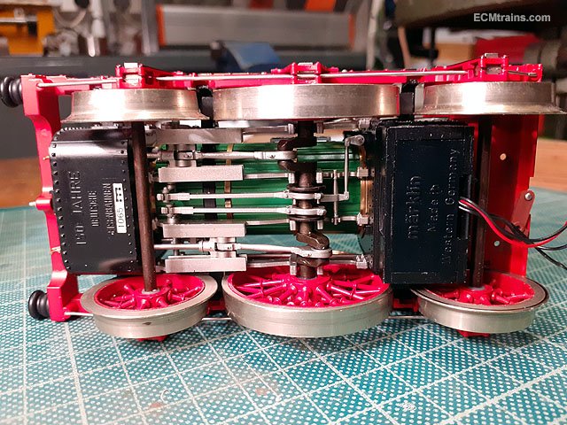
Adler up and running again- the wheels on the tender are spinning!!
- 9 replies
-
- 6
-
-
- adler
- adler marklin
- (and 1 more)
-
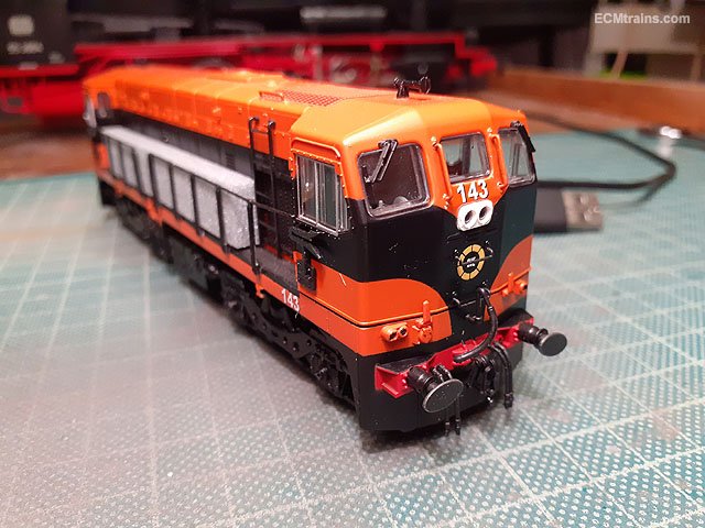
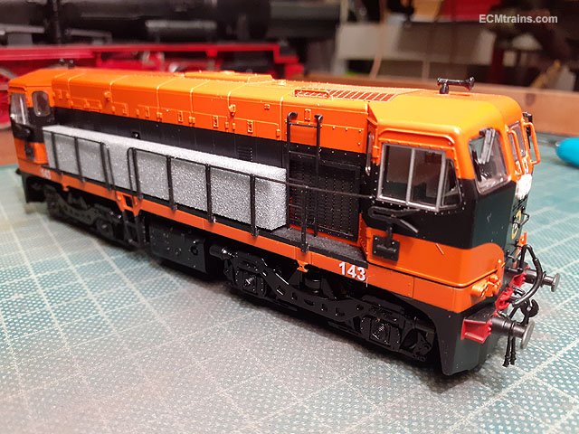
Hi jhb As NIRCLASS80 says above use a stick, or preferably a bud and add a small bit of T-Cut to soften the numbers, it leaves the paint nicely polished for applying the new numbers. Des in Studio Scale Models can supply decals for this, I'd recommend replacing all the numbers just to keep the font the same- nothing worse than having the new '5' not match the existing font! Here's one that I did earlier! converted to 143 to pull the 'Transition DART' with des's decals;- Eoin
-
oops! reminder is a bit late but...... Don't forget the Fair is on tomorrow!
-
Hi Colin R Drawings for no. 10 are featured in 'The County Donegal Railway Companion' by Roger Crombleholme, ISBN 1-85780-205-5, including some detailed photos. Also the 7mm Narrow Gauge Association's drawing book no. 6 has drawings for no. 10, ISBN 0 9513300 0 4. Unfortunately nothing on no. 9 Eoin
-
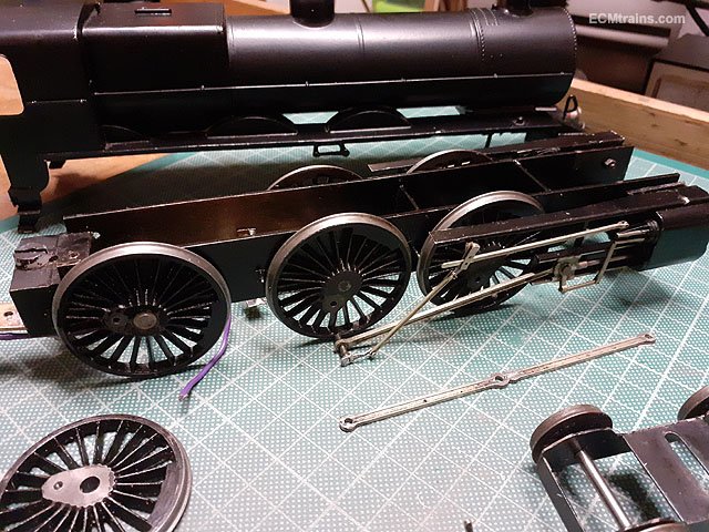
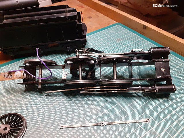
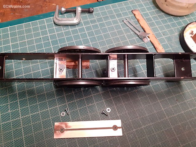
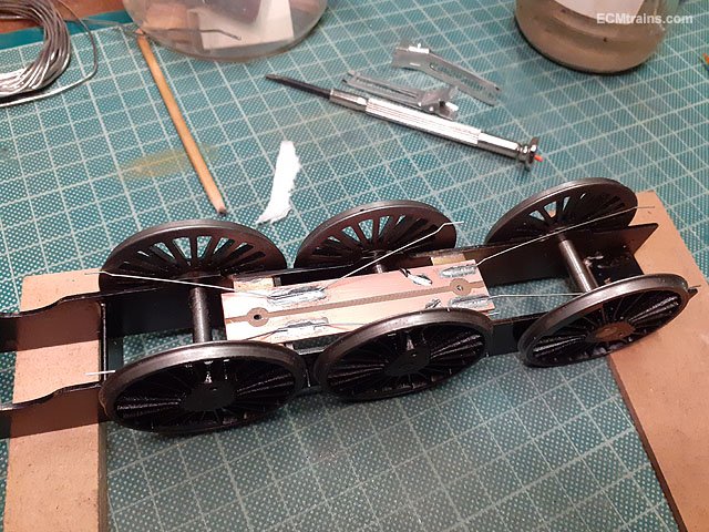
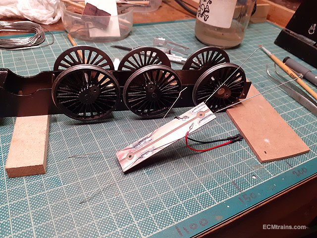
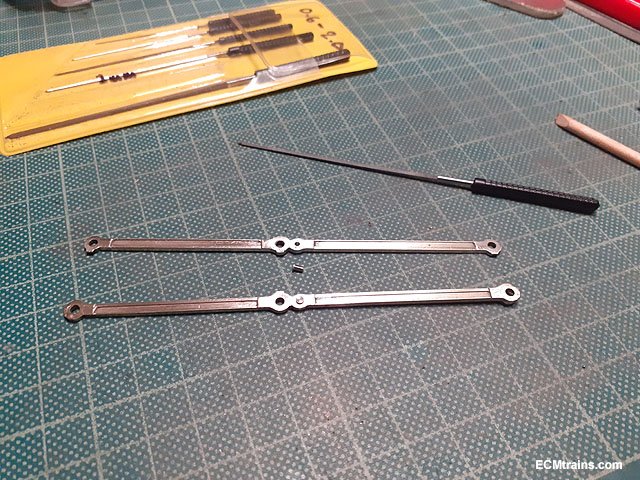
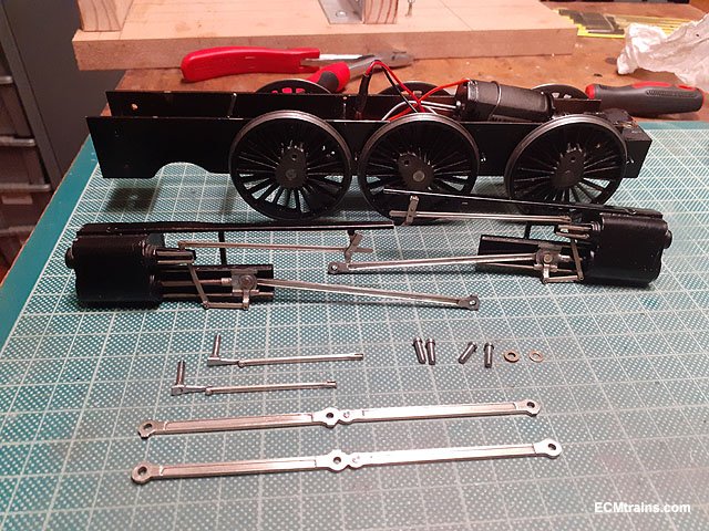
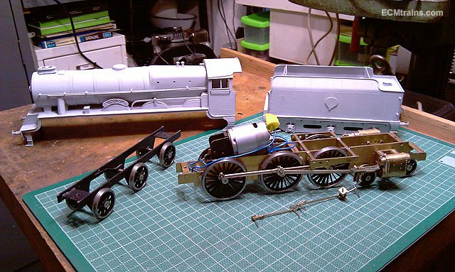
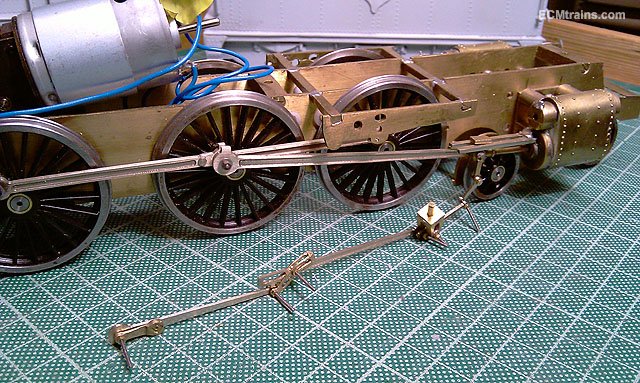
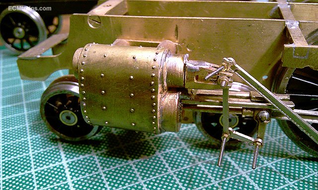
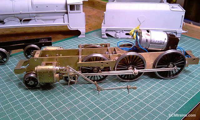
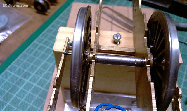
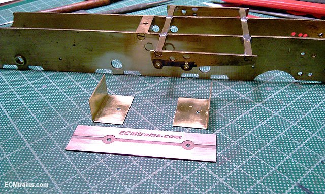
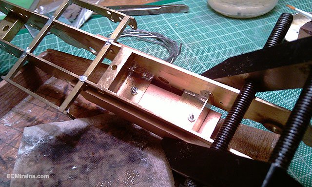
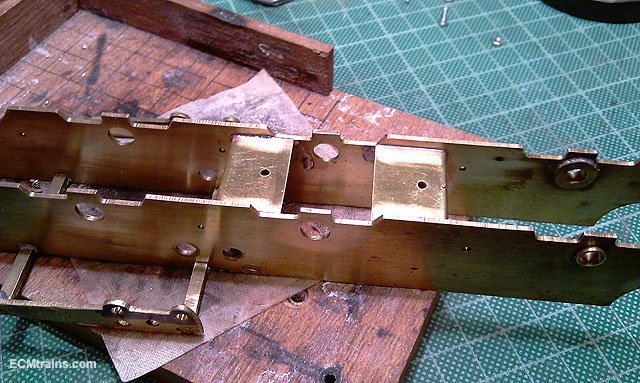
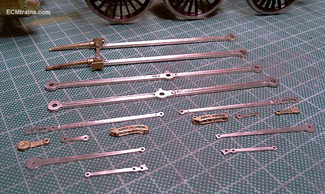
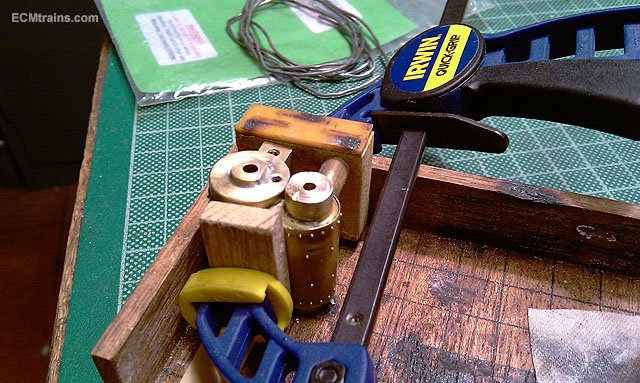
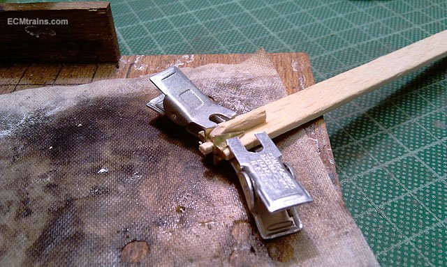
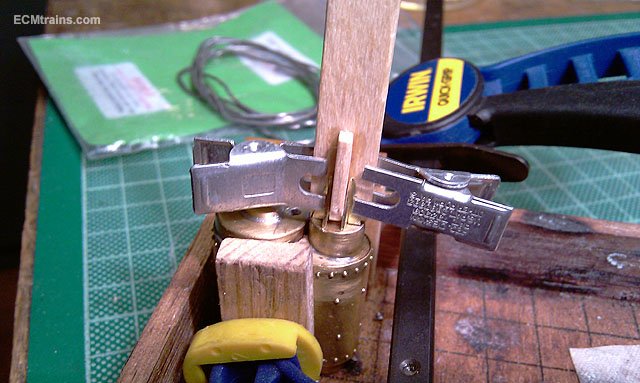
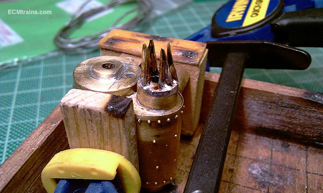
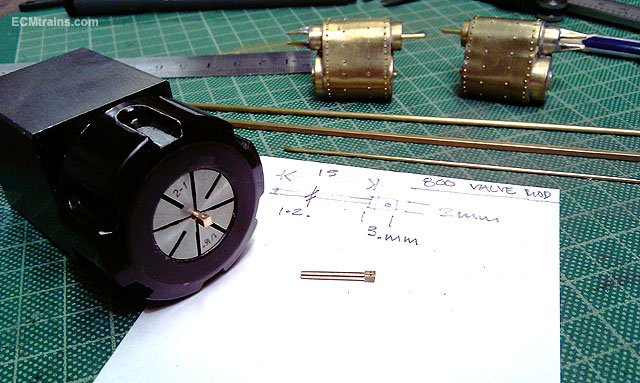
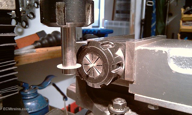
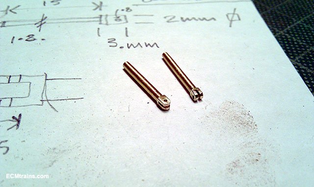
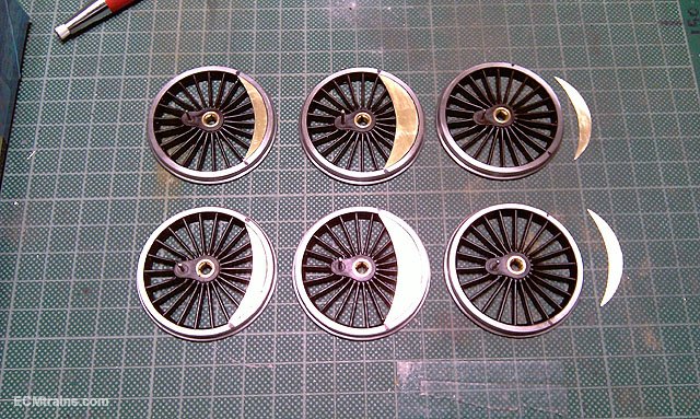
Another Class 800, this time it's 'Meadb' is in the workshop for completion- valve gear, break gear, wheel weights, some cab detail, painting & lining. As it came;- So I set about stripping down the chassis and came across a number of issues;- only two of the axle bearings were soldered into the chassis, the others had been super-glued in but all have come free to rotate with the axles- see photo of bogie above, their all loose to. The plunger type electrical pick-up system was very poor, some of the plungers were frozen in their housings and did not make contact all of the time. The chassis required a few more frame spacers- it was a bit bendy! So with a plan of action the frame spacers were made up from .5mm brass sheet in the 'L' shape for stiffness, a pcb copper clad pick-up board was cnc'd out- as I'm going with wiper pick-ups off this board- no stinking plungers! Holes drilled, M2 nuts soldered to the new spacers and the plate fixed with M2 bolts- this holds the frame spacers in when soldering them in the chassis. Spacers in, time to solder the axle bearings in. The coupling rods were cleaned up, to be used with the axle jigs to centre the bearings when soldering them in. I do this on a glass sheet with two rulers on edge to support the chassis by the axle jigs. Done. The cylinders were cleaned up after removing the old crosshead guide bars, the valve front end was drilled to take the valve rod housing that sticks out the front- done with 1mm dia brass wire locctite'd in. The valve back-end guides were cnc'd from .5mm brass sheet and folded up for soldering on. I came up with a lolly pop stick trick to hold these parts in position for soldering- a cross shape with a spigot that seats into the valve end and the parts clipped on? Worked a treat! The remainder of the valve gear was cleaned up and I noticed we're missing some parts- the Valve Rods and the Anchor Links! The link will be cnc cut from NS sheet with other parts later, but the valve rod requires a bit of machining- 2mm square bar was rounded up on the lathe with a file leaving a 3mm long square at the end, then cross drilled for a rivet, then .5mm slotted to create a clevis, after a bit of filing. I made these a bit fat as the holes in the valve housing are large. Wheels have been cleaned up and the wheel weights in .5mm brass being epoxied on. Eoin
-
The tender weighs a tonne also, I suppose making up for such a small loco so that it can pull something- my Gauge O Hibernia model is about the same size physical and it was a little loco. Yes the splashes would be a problem but I'd be more worried of being knocked back by those driver levers- they would swing back and forward alternatively which were used by the driver to adjust the valve timing. Eoin
-
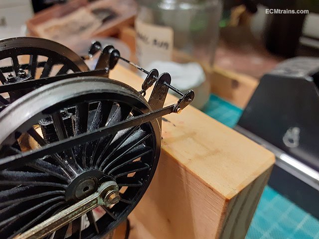
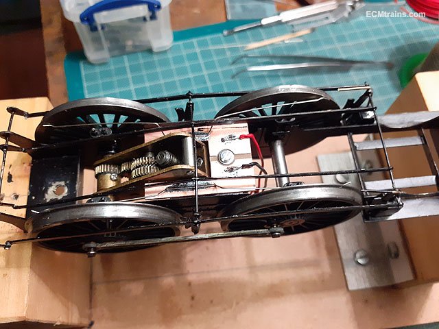
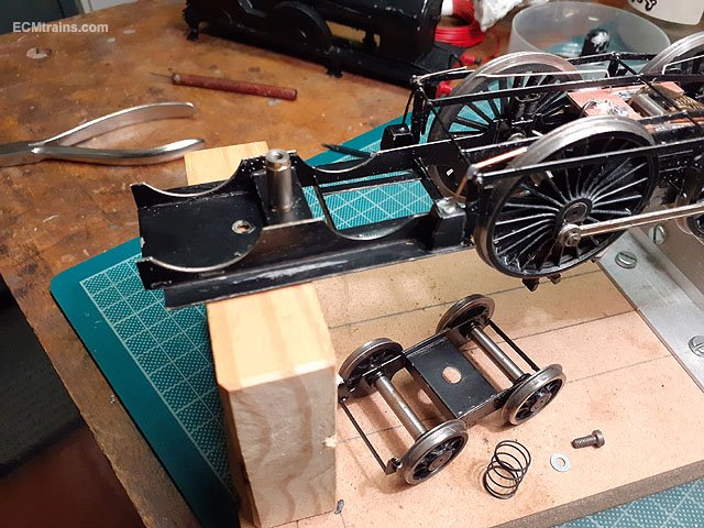
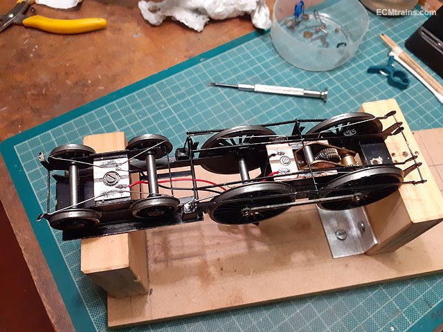
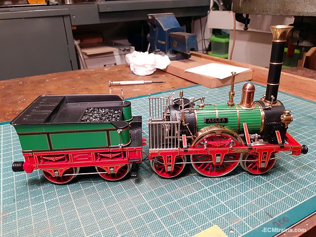
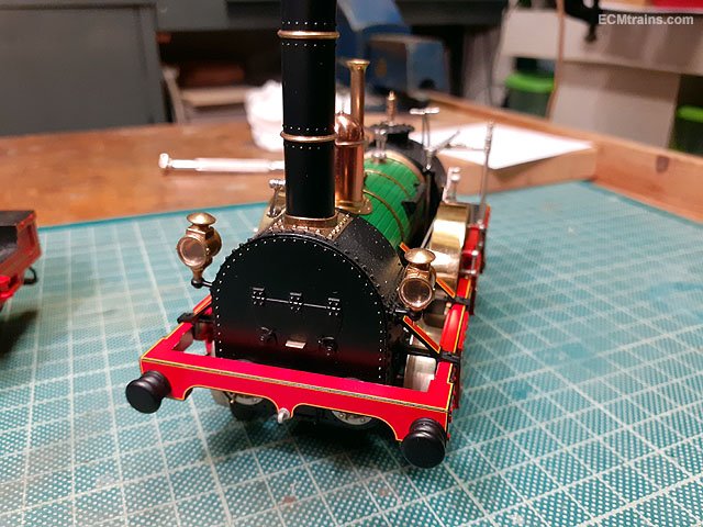
Here are a few photos of a Gauge 1 Adler loco in the workshop for some minor repairs, it's my next favourite loco after the Hibernia, and maybe a few others from the Dublin & Kingstown Railway era! It's a lovely model by Marklin and has some beautiful detailing- and working valve gear. Eoin.
- 9 replies
-
- 7
-
-

-
- adler
- adler marklin
- (and 1 more)
-
A tiller can sometimes be refereed to as 'The Wheel' so I think it could also be an 0-1-0! Eoin