murrayec
-
Posts
2,775 -
Joined
-
Last visited
-
Days Won
70
Content Type
Profiles
Forums
Events
Gallery
Blogs
Everything posted by murrayec
-
@Galteemore I used .5mm nickel silver sheet and .6mm NS wire for the hangers and rodding. @Georgeconna Yes, not all had these going by the photos I found, earlier photos of the class don't have them so I assume they re-used other buffers later which needed to be extended??.... Eoin
-
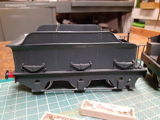
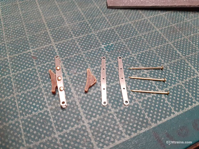
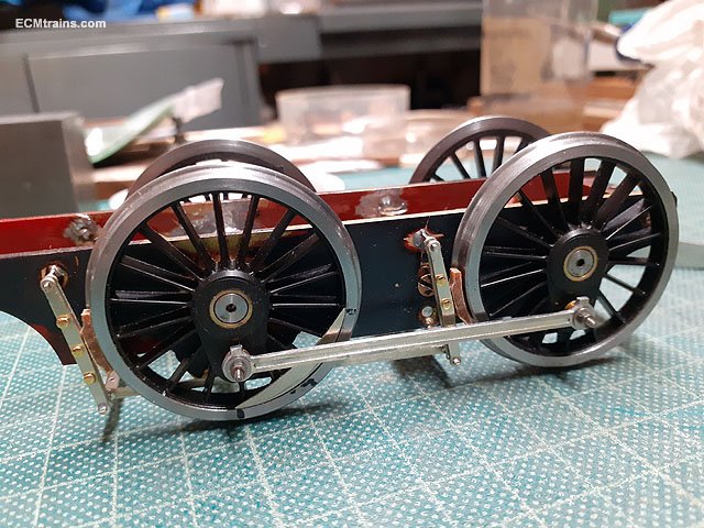
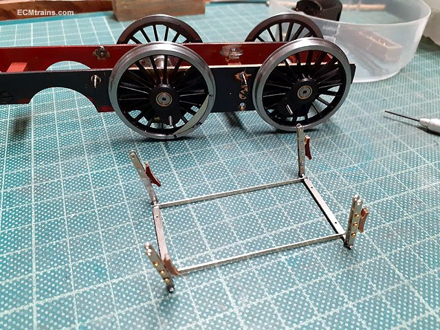
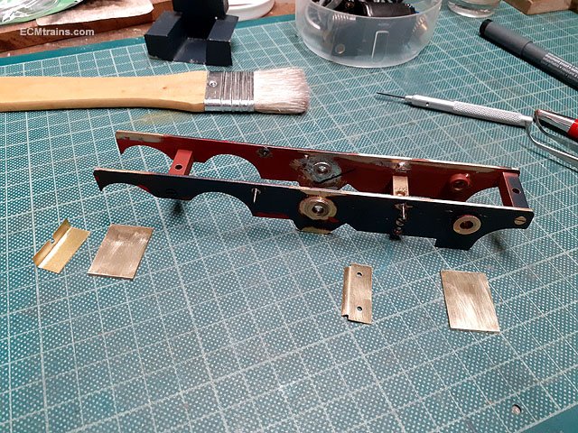
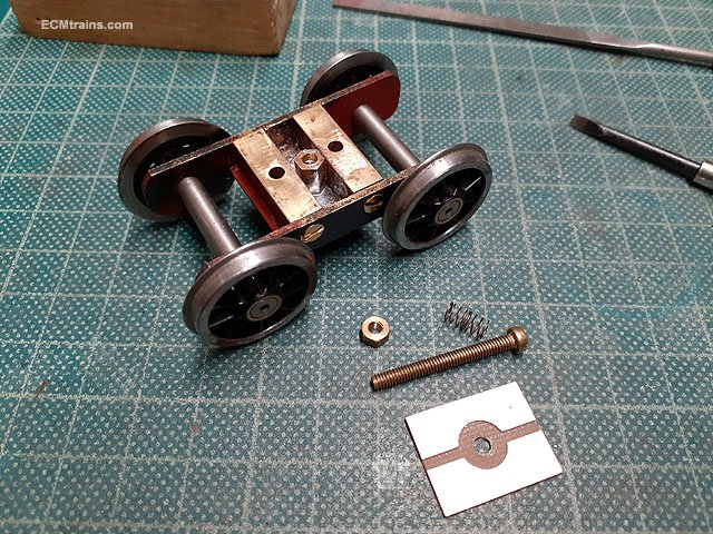
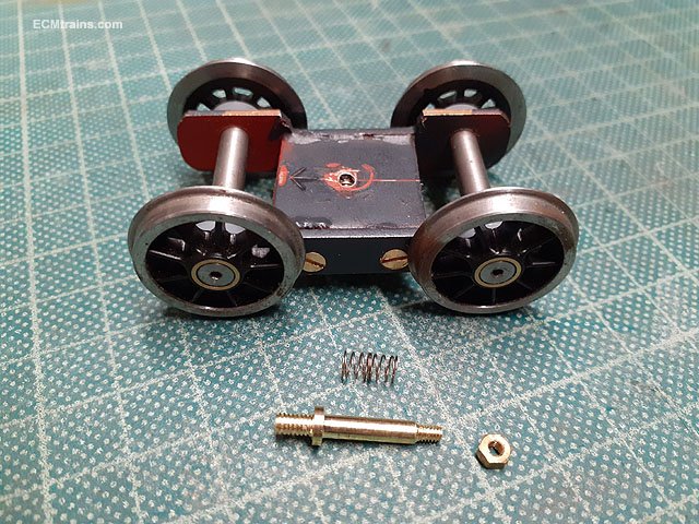
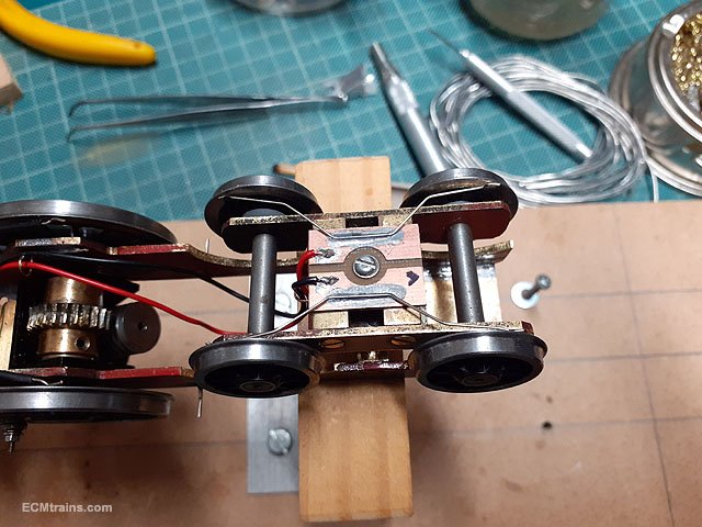
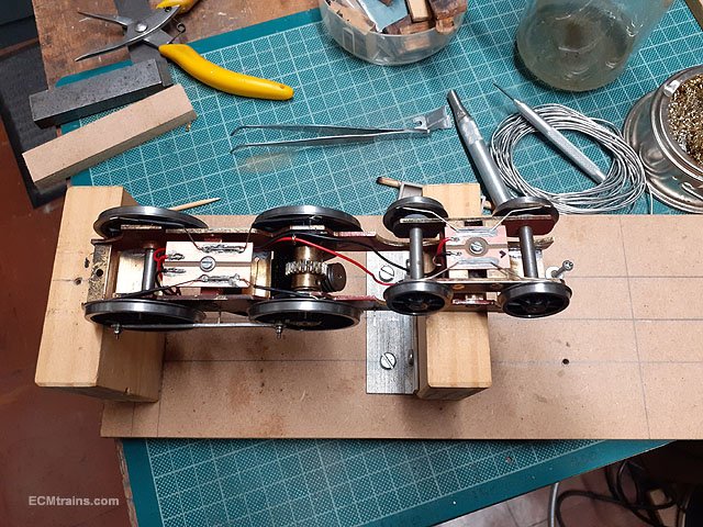
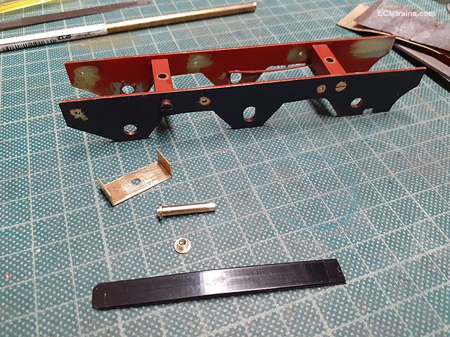
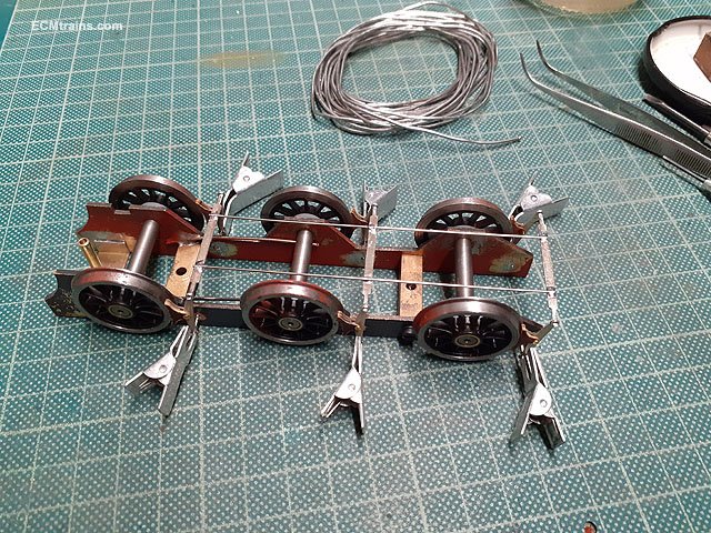
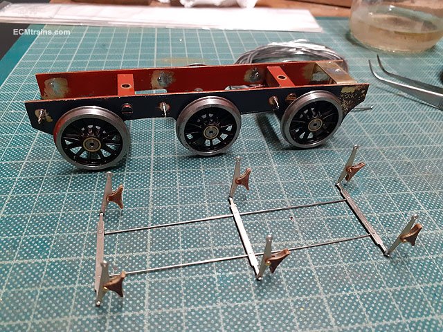
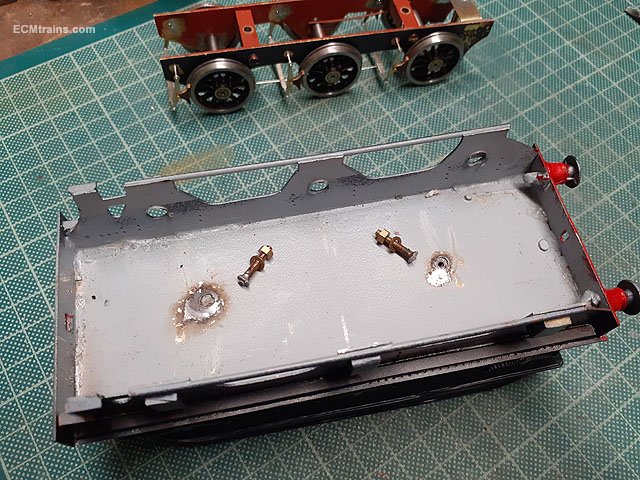
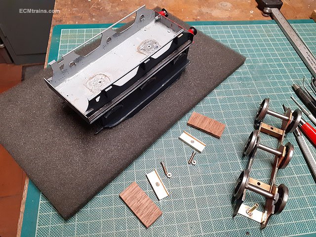
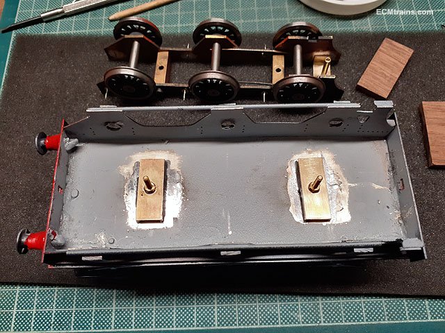
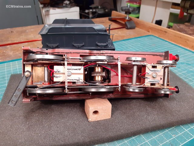
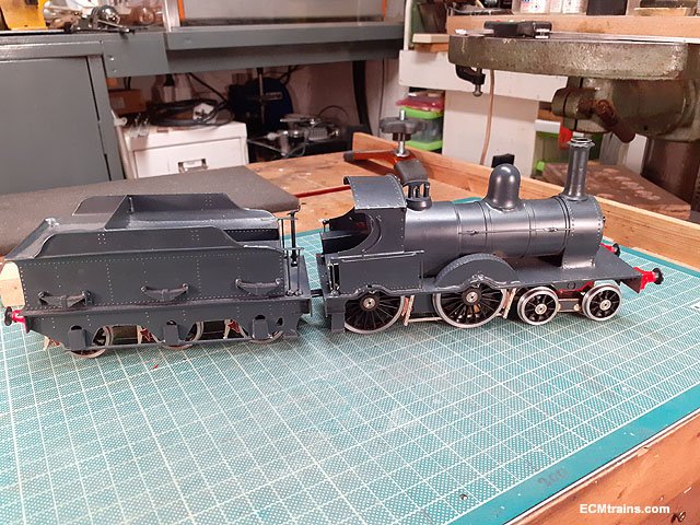
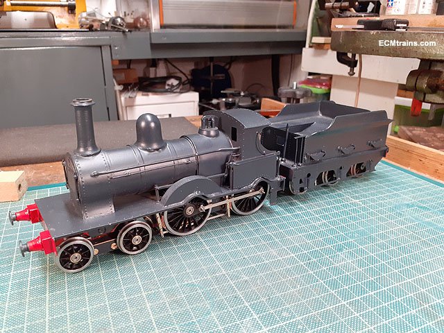
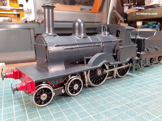
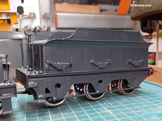
Here is another scratch built model by Mr B Kelly, a D19, one of my faves! it's in my workshop for coupling rods, break gear, electrical pick-ups and a few other bits. As it came. After measuring up, researching a few photos and doing the drawings parts were cut out of .5mm nickel silver- wheel weights, coupling rods, break gear.... The chassis was a little fat, the wheels were locking up when assembled and one axle was slightly out of line, only noticed when fitting the coupling rods- one side would go on but not the other! So that set of bearings needed a bit of adjustment and the other set had a .9mm skim taken off the faces. Some of the chassis screws were cheese head so I replaced them with counter-sunk and holes for the break hanger spigots were drilled in the frames. Jigged up to solder the bearings back in. Loco break gear coming together, these locos had double hangers with the shoe sandwiched between. The shoes are cut from Tufnol and brass .7mm pins were used to assemble. Breaks on. Breaks off. The assembly can be sprung off for painting and removing the wheels. After fitting the coupling rods I noticed they fouled the underside of running board!, so a few 1.2mm brass spacers were prepared and soldered onto the top of the frames. I also made a motor strap to lift the motor up at an angle and save space in the cab. The bogie truck was then tackled- needing a pivot, spring and a bit of side play, also going to get electrical pick-ups installed. A deep hex nut was soldered to the underside to take the pivot bar on top and the pick-up plate on the underside. I also replace the frame spacer screws from cheese-head to counter-sunk and installed a plastic washer behind each wheel. A pivot bar was turned up on the lathe and tapped 8BA to fit into that hex nut in the bogie frame. The pick-ups were then installed on the underside. This is the full pick-up system, diver wheels & bogie. A sideways slot was milled in the frame spacer to give the bogie side-play and a .5mm brass angle plate was soldered onto the bogie front to stop full rotation. The frames also required some mod at the rear wheel arch to allow clearance. Up and running. The tender was next, break hanger holes drilled, and at front- these are parts for the draw bar, the brass to be soldered between the frames and the plastic strip drilled as the draw bar with the little brass bush to allow it pivot on the back of the loco. Breaks going on and draw bar assembly installed. Breaks done. The tender had its mounting bolts broken off, so some repair needed, also spacers are needed to level the tender with the loco- using two blocks of hardwood! Done. Draw bar drilled and installed, this is the body mounting screw, the front end is held with a brass tong soldered to the back of the buffer beam. And its done, going back to its crew for a bit of painting and maybe some coal! Eoin

- 24 replies
-
- 15
-

-

-
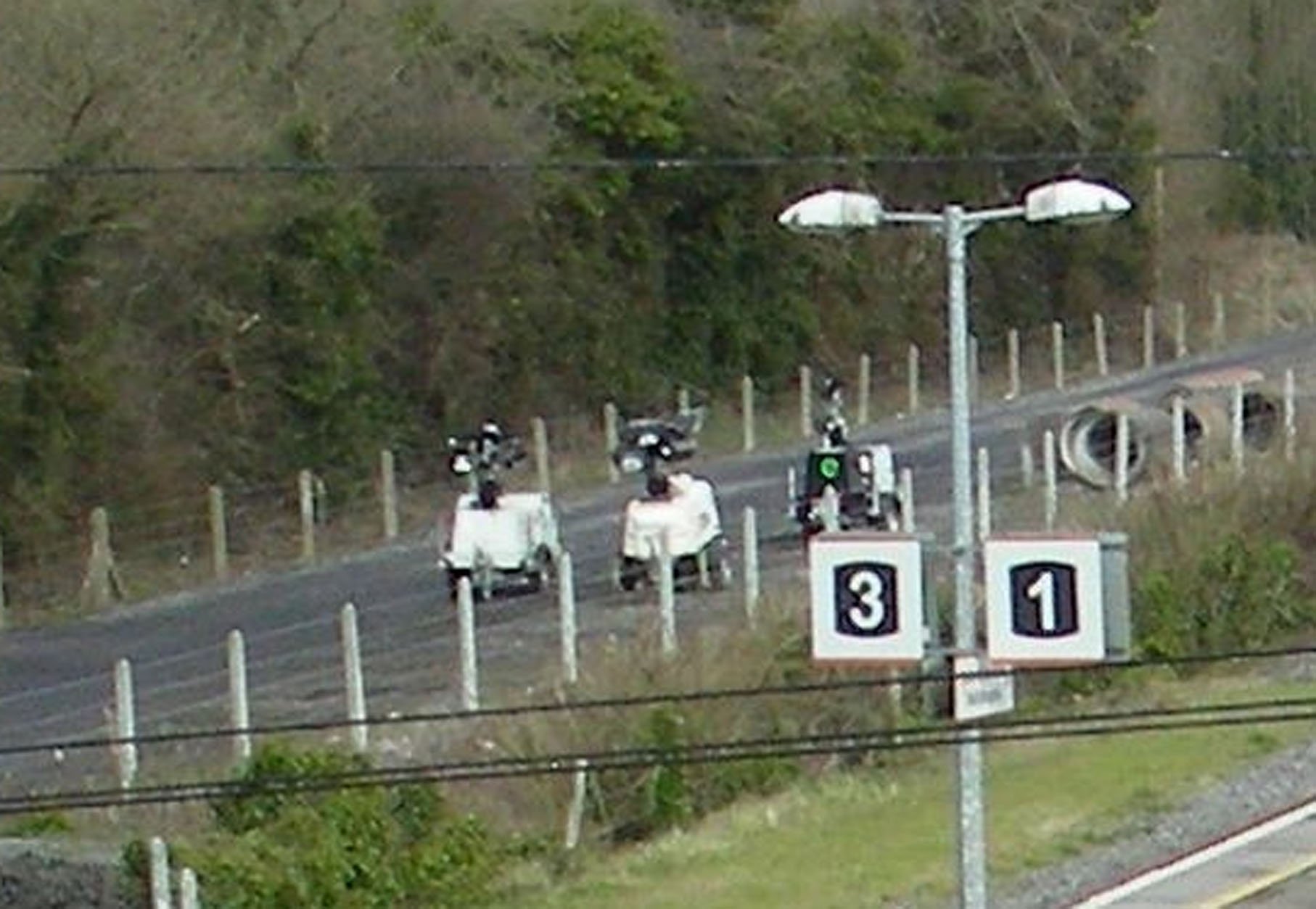
3 robots patrolling the perimeter!! Eoin
-
When were were kids there was a farmer chap in Monkstown down the lane between St Patrick's church and the post office, Michael (johnny) Lawlor was his name, he farmed a few cows n pigs and the place stank to high heaven and so did he. He, his horse (which never had a wash) and a single axle deep cart were a regular feature on the local roads delivering cow-shi to the local ladies who did roses and used his product as fertiliser, he also collected kitchen waste from the ladies for feeding the pigs. Twice in my early teens I welded broken struts to the axle on his cart, the stink I can still remember. When the jobs were done his offer of payment was in cow-shi which I politely passed on to our neighbour who was one of the ladies that did roses. As far as I know he farmed there into the early 80s, the farm is now a town-house development called Alma Park and the area smells a lot better. The series of documentaries by David Shaw Smith 'Hands' is an incredible archive on this subject and many other old time subjects throughout the country;- Eoin
-
I can just see you now- sitting around the billy can slurping the tae and swapping Tufnol jokes those were the days....... Eoin
- 45 replies
-
- 4
-

-
-
- gsr class 551
- j26
- (and 1 more)
-
Just noticed when looking over this thread, after a long time, I describe the material for the break shoes as 'Delrin' it's not! it's Tufnol, a great material for the modeller. Made from wood/paper, it has great structural qualities, easy to be worked and can be machined. Eoin
- 45 replies
-
- 4
-
-

-
- gsr class 551
- j26
- (and 1 more)
-
until
-
The March date for the Train & Model Fair;-
-
@Mike 84C Yes it's quiet at the moment, I did have it down from the top shelf about a week ago to review progress and keep it in my mind! There are to many projects on at the moment, I'm not taking on any new work until current client projects are completed, then I can get back to my stuff- the C is on this list. I could be persuaded to run off a few bogie sides, a chassis plate and maybe a battery box....... Eoin
-
I'm building one of the 'Bat' Kits from that clean-up, it's just on a stad at the moment as I have several projects on the go- to many! Eoin
-
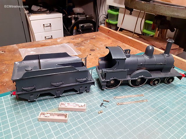
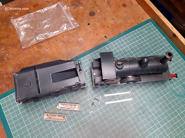
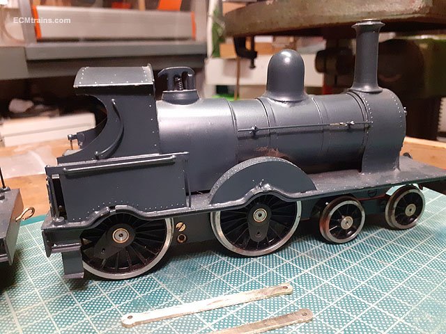
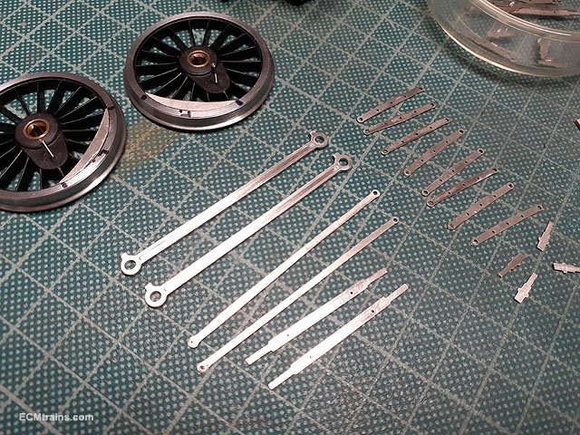
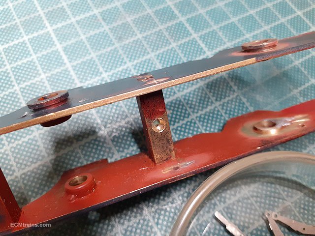
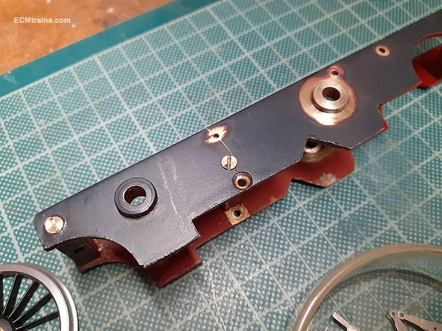
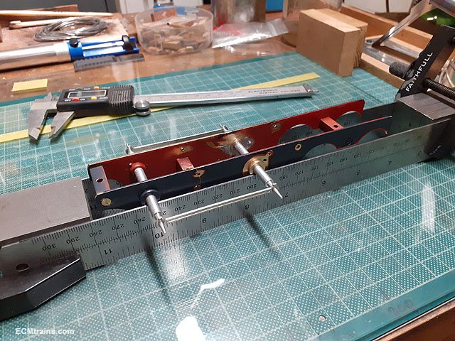
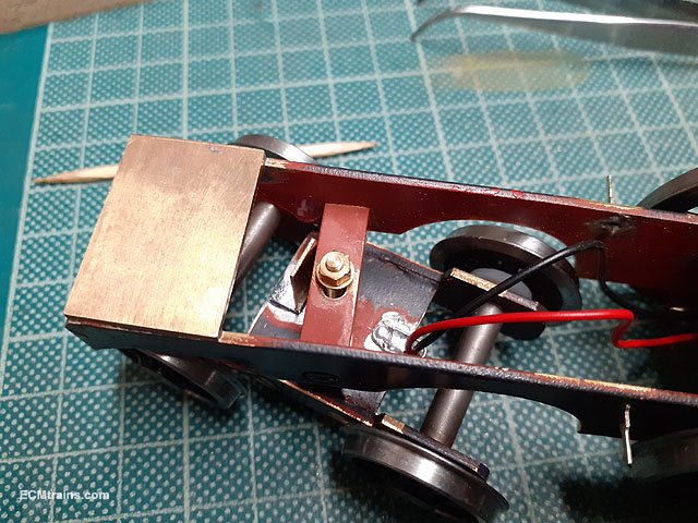
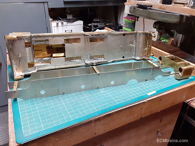
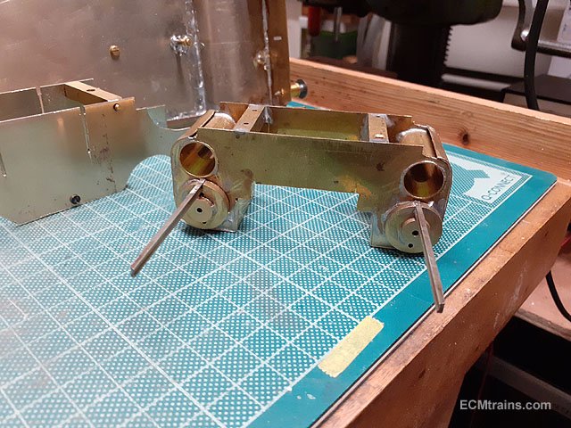
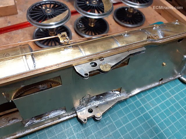
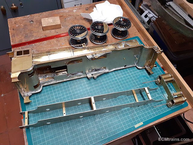
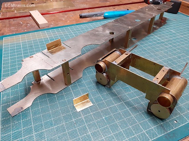
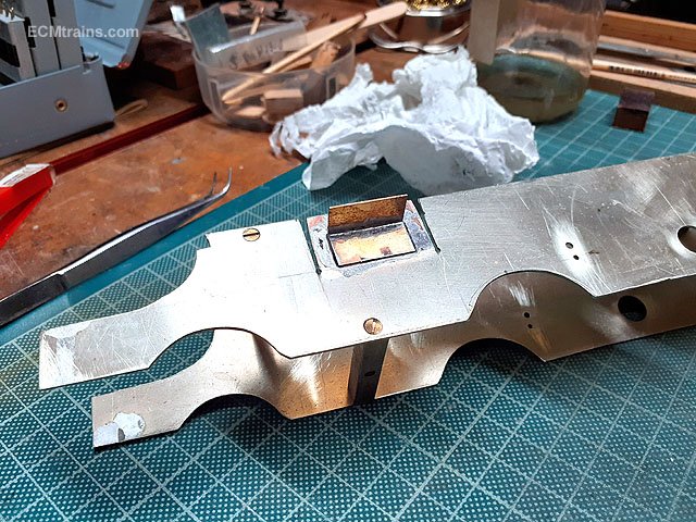
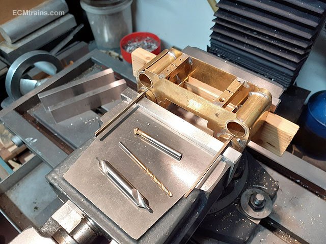
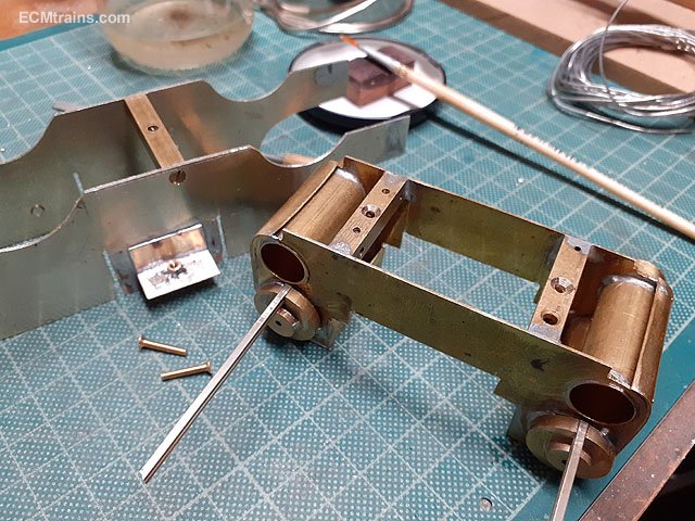
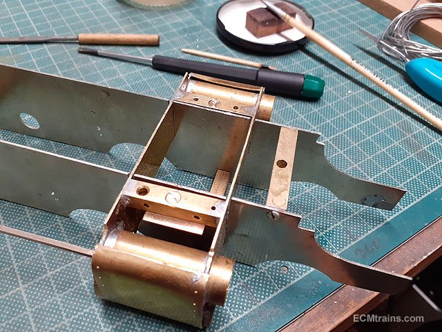
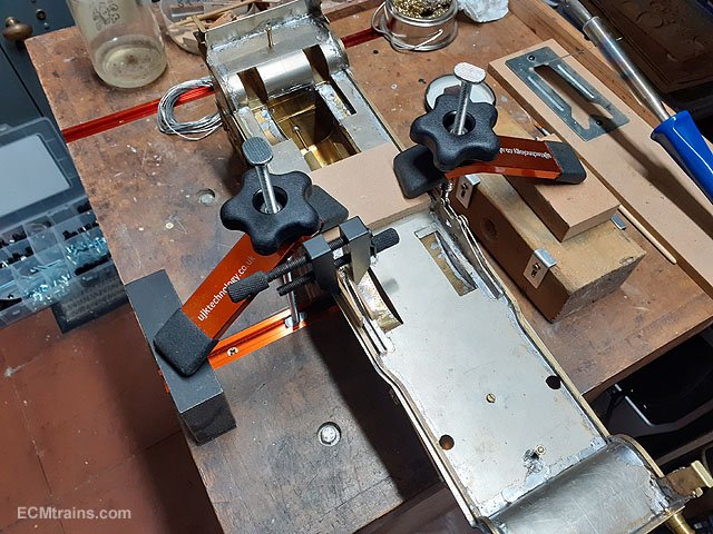
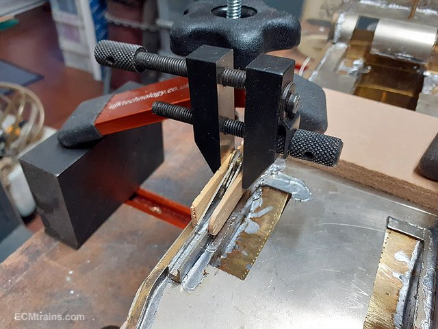
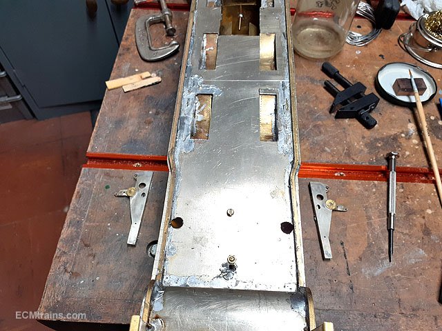
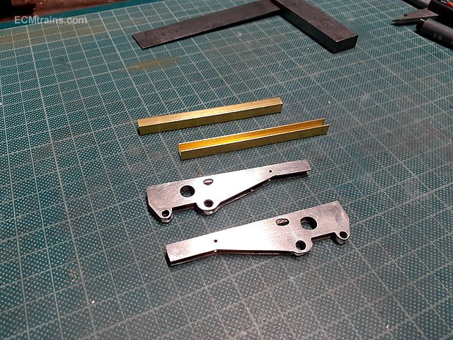
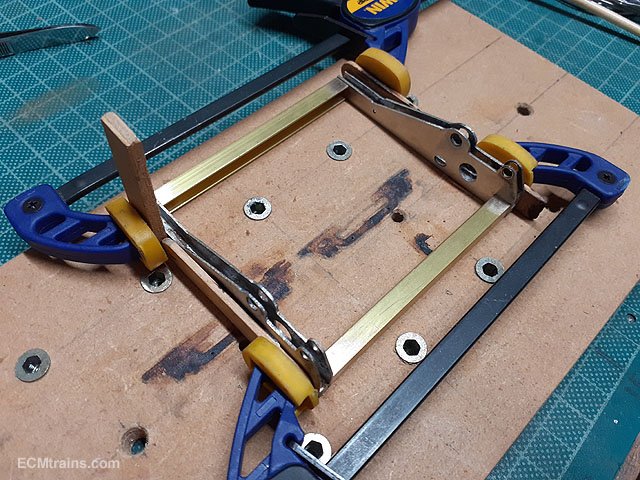
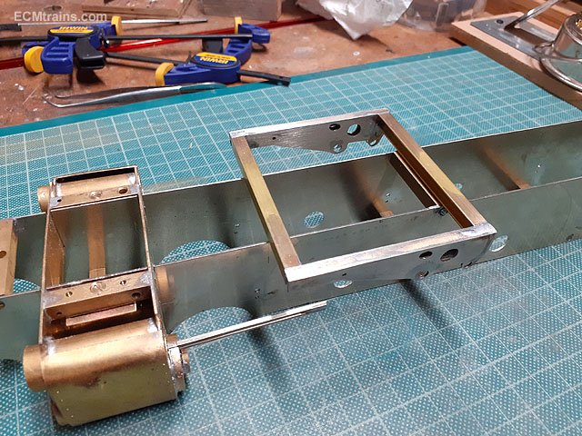
So I eventually got going on this project, after a few contemplation evenings and pencil sketches I set up a drawing and worked out a plan of action. The chassis, cylinders & motion bracket would be tackled first as this will aid in finalising the drawings for the valve motion gear. After stripping down the chassis I decided the cylinders need to be fixed on but, I may need to remove them so a bolt on affair was decided. The motion brackets are soldered to the underside of the body running board! this is not great, I prefer to work on the valve gear on the chassis alone, rather than having the whole loco on the bench and making things unwieldy and difficult, so the plan is to remove them from the body and install then on the chassis. This will make it easier to take the body off in the future as only one rod has to be undone- the oil pump rod, the other way most of the motion gear has to be dissembled and would be a real pain just to access the motor! All asunder. The chassis is a bit bendy, the new motion bracket and its frame will help. Also the counter-sunk screws on the frame spacers are not counter-sunk- so that will be done. Valve cylinders need end plates and a few other things. The motion brackets as is. .5mm brass angle plates were made up to fix the cylinders to chassis with 8BA screws through those frame spacers behind each valve cylinder. Cylinder chassis plates soldered on and the frame spacer screws counter-sunk. Holes about to be drilled and counter-sunk in the cylinder bracket, these holes will be used to spot through to the chassis plate for drilling for the captive nut. Captive nuts soldered on. Done, plates need a bit of trimming later. Removing the motion plates, this is the jig set-up- as both hands are required for the soldering iron and pulling at the parts. Clamp fixed to bracket with wood insulators between so that the clamp doesn't take all the heat, holds the bracket together- as its three pieces soldered to the running board, and something insulated to pull on to save my fingers. Done, the 100 watt iron was used only touching the motion brackets and loads of flux, once one gets the temperature up they came away relatively easy! Brackets cleaned up and two brass bars cut to size for holding the brackets to the chassis. Soldering up. Test fitting the assembly and marking the chassis in prep for cutting the slots in the frames to house it. Thats all for now. Eoin
-
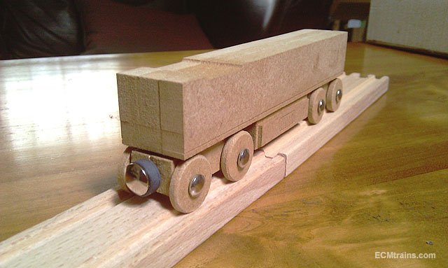
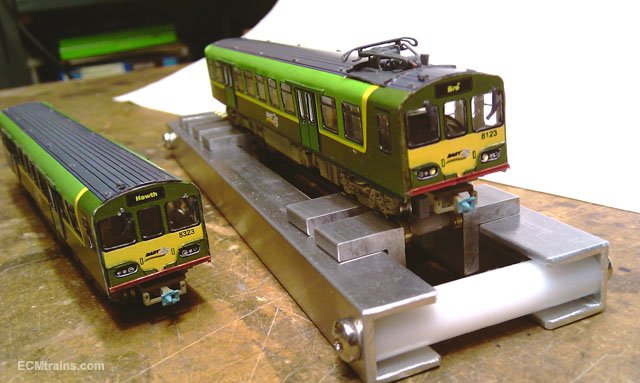
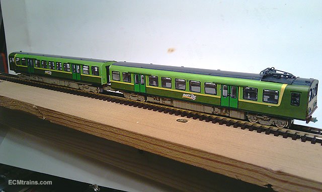
I make me own for the toy DARTs
-

Walker Diesel Class F - ECMbuild in 4mm for OOn3
murrayec replied to murrayec's topic in Irish Models
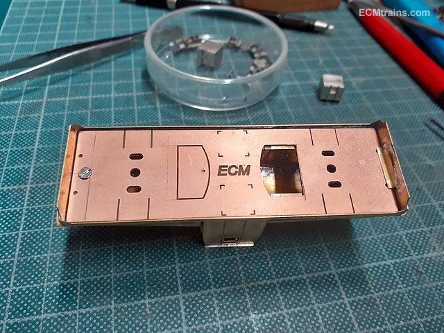
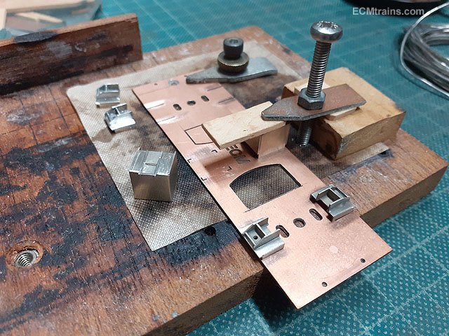
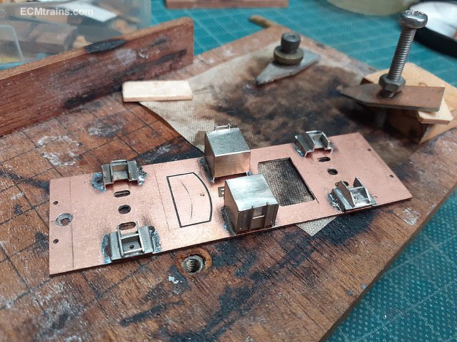
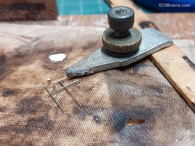
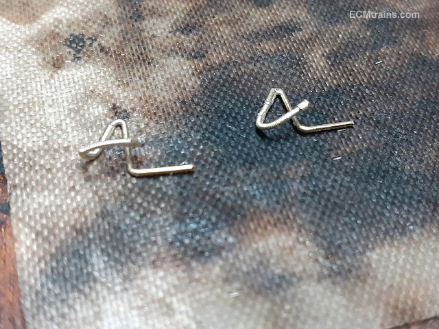
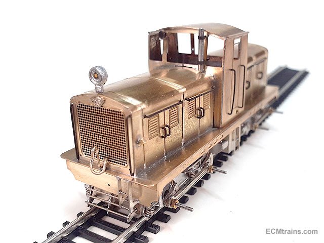
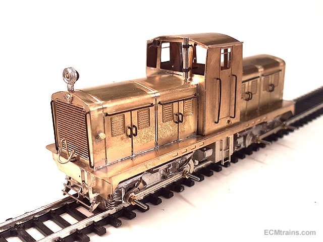
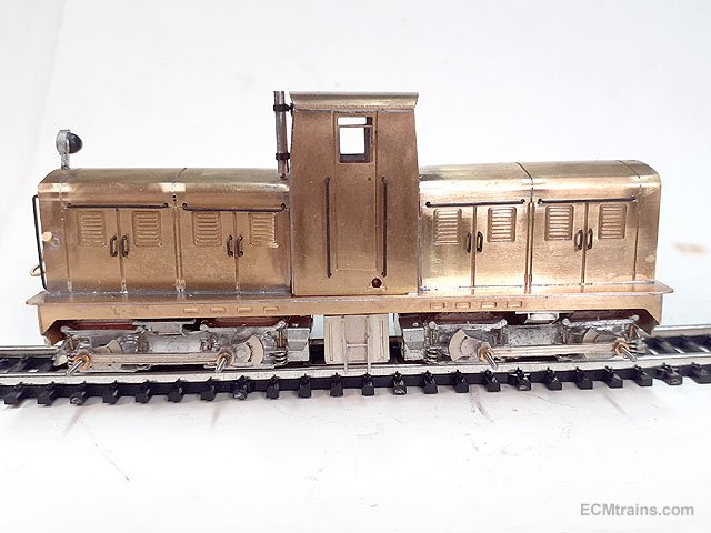
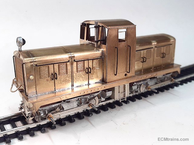
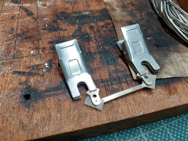
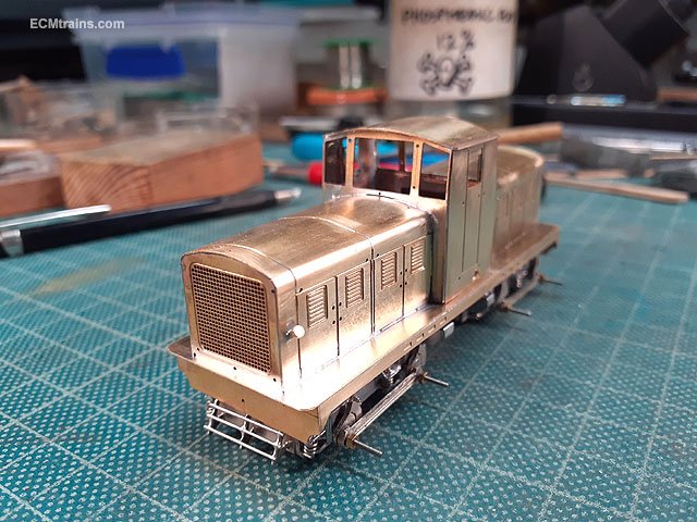
Thanks guys for all the great comments. Fixing of body to chassis was worked out, I settled on a brass tab at one end and a M2 counter-sunk screw at the other with the nut soldered onto the body. Everything is so tight for space the screw has to be installed in the chassis plate before the bogie is bolted to the plate!! Jigging up to solder the fuel tanks and bolsters to the chassis plate. Done. Front NS ladders being soldered up, which will be soldered to the buffer beam- if one can call it that? Vac pipes soldered up using .5mm brass wire, .8mm brass tube bits, and guitar string. Well then- except for the coupler system, it's ready for painting. So I joy-rigged the after painting parts- headlamp, exhaust, horn, vac pipe, handrails and the Walker Brothers front plate to take a few naked photos. Eoin
- 136 replies
-
- 9
-
-
-
- class f
- west clare
- (and 1 more)
-
@LostCarPark The mid section is 12mm I'm using the same chassis for the 071, just the chassis plate will be longer. Eoin
-
Walker Diesel Class F - ECMbuild in 4mm for OOn3
murrayec replied to murrayec's topic in Irish Models
Thanks Garfield Have to agree with you there- such a pity Eoin- 136 replies
-
- 1
-
-
- class f
- west clare
- (and 1 more)
-
Walker Diesel Class F - ECMbuild in 4mm for OOn3
murrayec replied to murrayec's topic in Irish Models
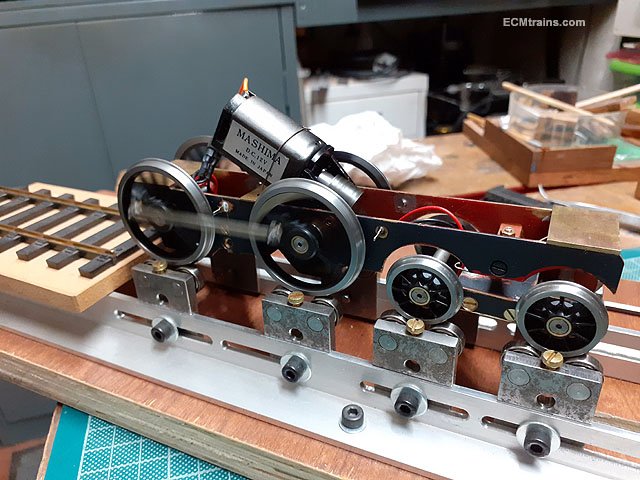
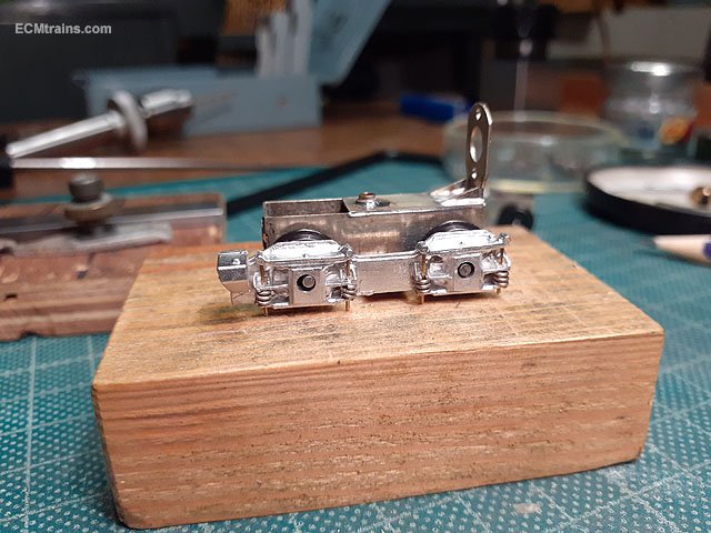
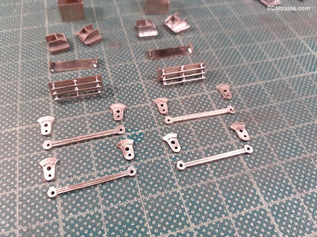
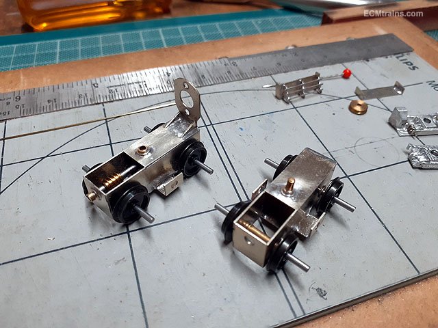
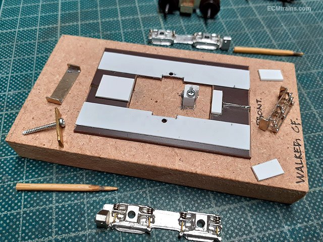
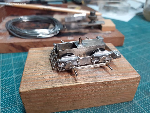
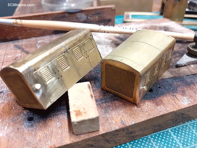
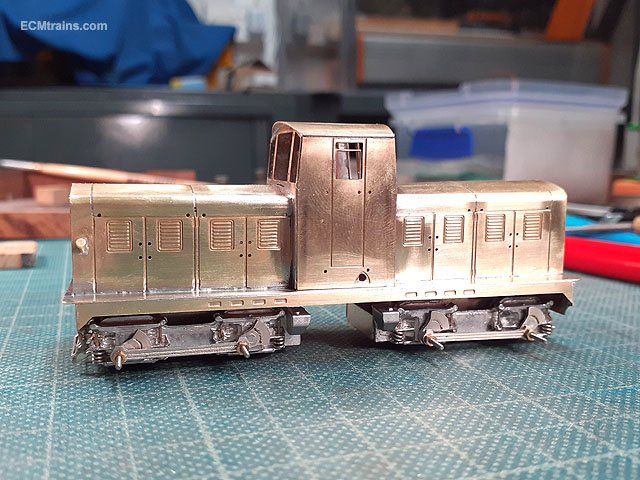
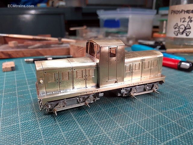
The Walker Diesel Loco build got a bit of attention over the last month or so, after making further mods to the bogie sides the extended axles were cut n sized and all the gear was set up to build the bogies;- The gears were glued in with Loctite, small brass sleeves also around the axles on the inside of the bogie to hold the wheels on centre and stop them shorting on the bogie frames. I decided to glue the sides and stretchers to the bogies with epoxy, it was a bit problematic getting the soldering iron into the space between the wheels and the sides, also it would be easier to dismantle if required- so epoxy takes time and that means a jig to hold every thing in place for the glue to set. MDF, styrene card and a screw clamp- sit the bogie in the space in the middle and screw down to hold. I first used .7mm steel rivets to join the cranks to the connecting rods, soldered at the rear with a bit of tracing paper between so the cranks would not get stuck also. This proved problematic when fitting the crank assembly to the axles, there was a slight misalignment with the centres of the rods and after several attempts of de-soldering and making adjustments I changed tack and settled for 14BA screws n nuts to fix the rods to the cranks, which made the job a lot easier to get them adjusted. Only drawback is we now have nuts to hold the rods which on final fitting will be filed down after Loctiting. The body was attacked next with the radiator filler caps being soldered on the bonnets, these are small brass turnings from the lathe. Then the bonnets & cab were soldered to the running plate and cleaned up for a test fitting to the chassis. I couldn't resist sitting the assembly on the chassis and taking a first look at the loco with it's wheels on. Very close to painting stage, just have to put the under-frame parts on the chassis, set-up and check the electrical pick-ups which will be installed after painting. Eoin
- 136 replies
-
- 7
-
-
-
- class f
- west clare
- (and 1 more)
-
@LostCarPark There are very few off the shelf chassis suitable for the 141 because of running boards from cab to cab! most chassis have the motor way to wide to allow for this. The chassis I'm developing for this project- see beginning of this thread above, allows for the 141 design.... Eoin
-
@LostCarPark Yes card rolling stock is on the 'cards', I have artwork for- cravens, laminates, 6 wheelers and a few others set up- but the usual time restrictions are involved! I do do a Gauge N DART;- I have built 3 of these so far. I had a meeting with my printer guy this week and Xerox have come up with a solution to the orange printing problem! so I expect some new test prints in the coming week....... Eoin
- 55 replies
-
- 3
-
-
- 141 gauge n
- 141
- (and 1 more)
-
Hi Guys The Train & Model Fair this Saturday is a one off, the club house is booked for every Sunday in February for Wheeler's campaign on introducing new cyclists to the club & sport. Eoin
-
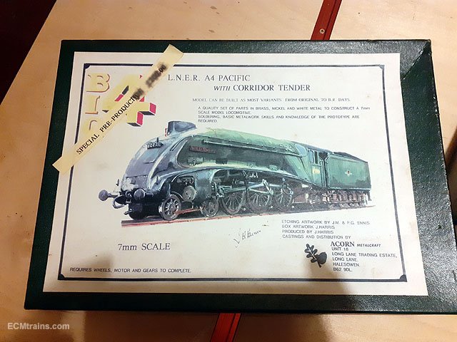
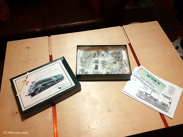
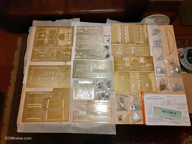
Came across this Gauge O Acorn Kit at the Stillorgan Toy Fair today, could not resist so I bought it. Its staggering the amount of parts in the box, etched brass, nickel silver and white metal- bags of...... 14 etched sheets approx A4 size, that instruction book down in the corner is A4 size for scale idea, the book is about 50 pages! To busy on other projects at the moment so will have to put it away for some rainy 5 years work in the future
-
- 7
-
-
-
-
CIE Laminate Coaches - Worsley Works - ECMbuild in 4mm
murrayec replied to murrayec's topic in Irish Models
@DiveController Its on the list to do but I'm a bit busy at the moment- I need to beef up the masters and make the moulds again, it was rather difficult to mould the sides I made for this project because some of the detail parts of the masters were to thin, the white metal would not flow by gravity to fill the mould completely as cooled to quickly. Thicker parts should hold the heat a bit longer?? ...... I have a number of orders for these so hope to do it soon! Eoin -
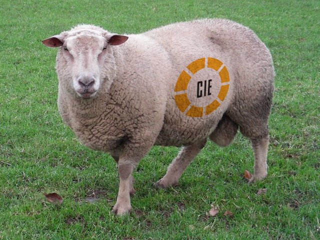
Their harder to put logos on, their a moving! Eoin
-
Maybe this will help.....
-
Hi David It's all looking excellent and congratulations on the win, nice trophy and well deserved. Eoin
-
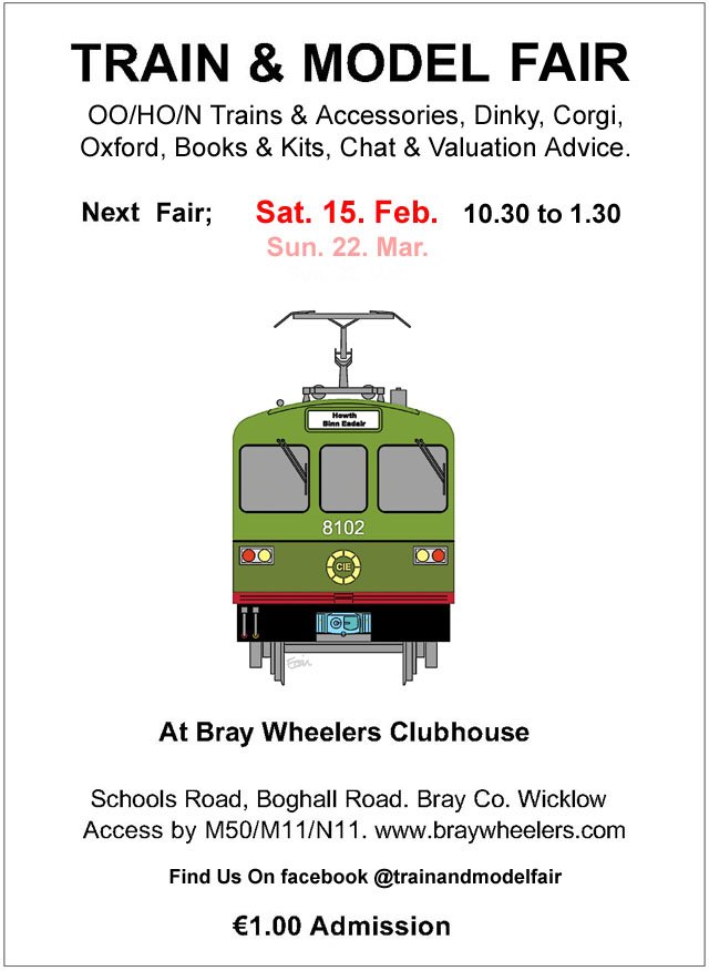
The February date for the Fair, note due to hall availability the Fair is on the Saturday;-