murrayec
-
Posts
2,775 -
Joined
-
Last visited
-
Days Won
70
Content Type
Profiles
Forums
Events
Gallery
Blogs
Everything posted by murrayec
-
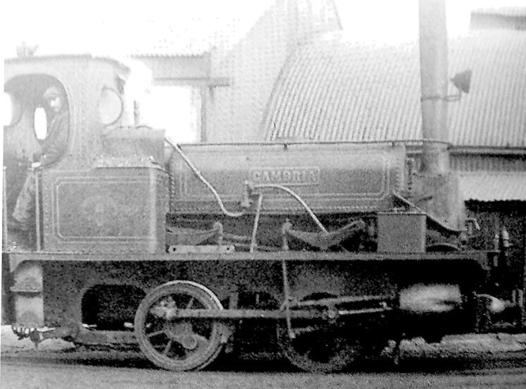
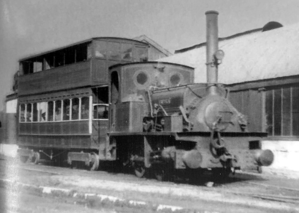
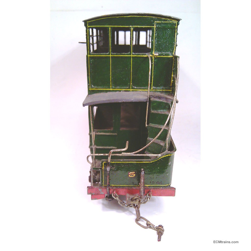
@Midland Man Between these two photos- yours and JHB's above, also if a backend one can be found, one would have enough info to set up a model;- Eoin

-
No I don't have that. Eoin
-
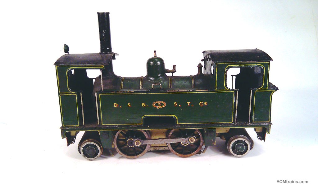
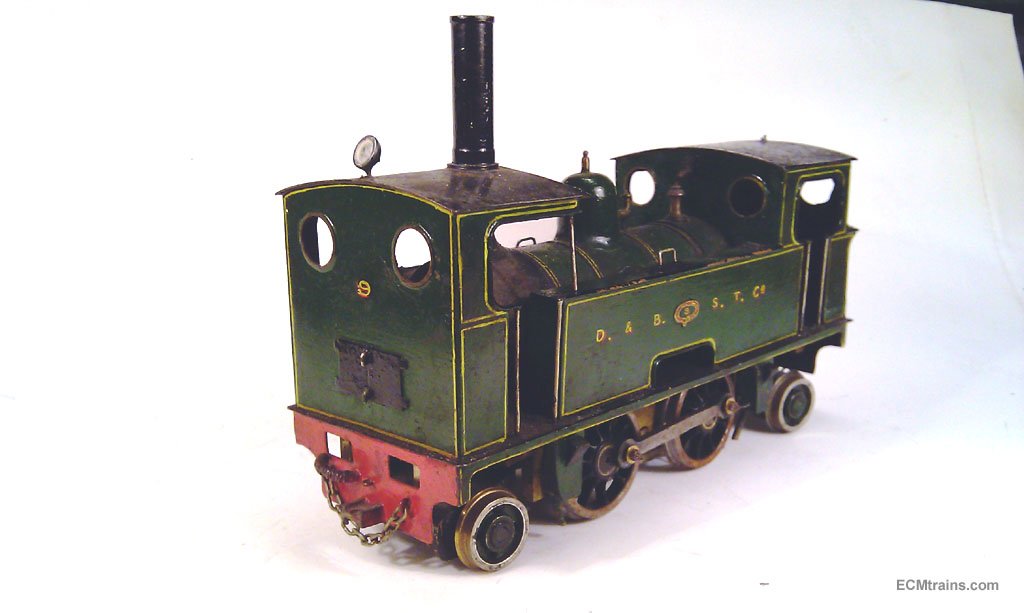
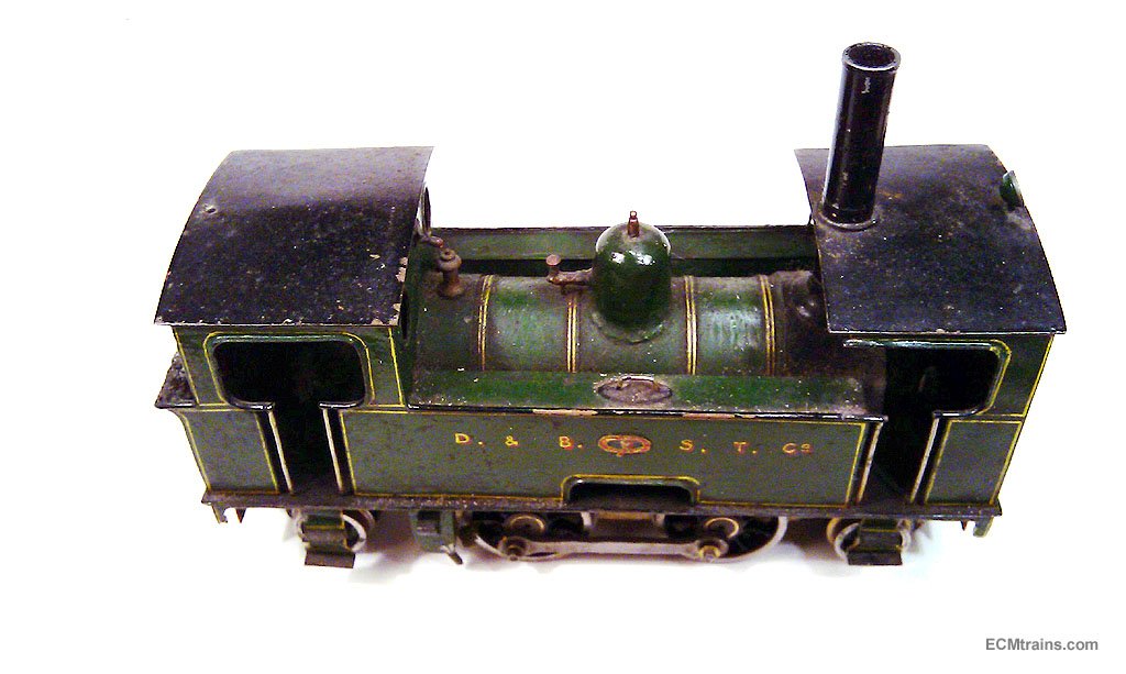
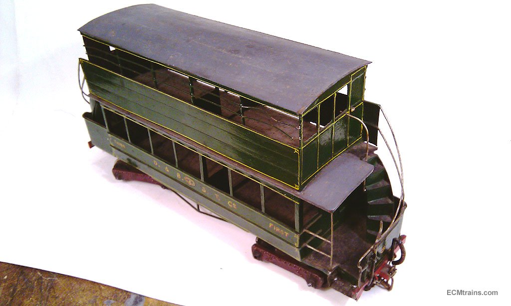
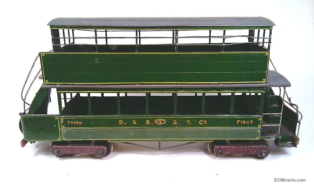
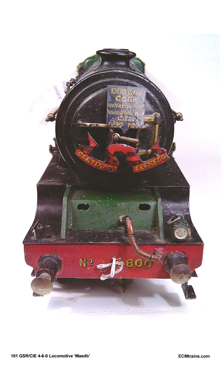
Here are a few photos of the one I worked on, these photos are of the models before the conservation work was done, unfortunately I cannot locate the work done photos;- Eoin
-

Walker Diesel Class F - ECMbuild in 4mm for OOn3
murrayec replied to murrayec's topic in Irish Models
Yes, I've been waiting for this moment for a long time..... Eoin- 136 replies
-
- 1
-

-
- class f
- west clare
- (and 1 more)
-
Walker Diesel Class F - ECMbuild in 4mm for OOn3
murrayec replied to murrayec's topic in Irish Models
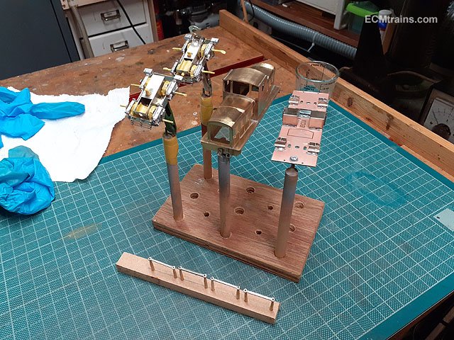
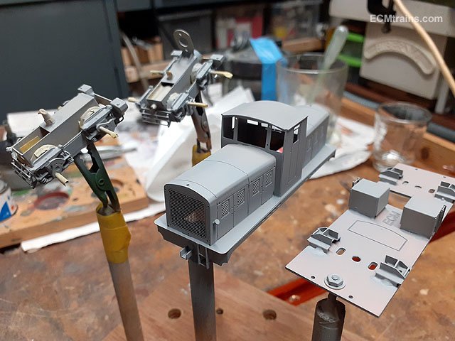
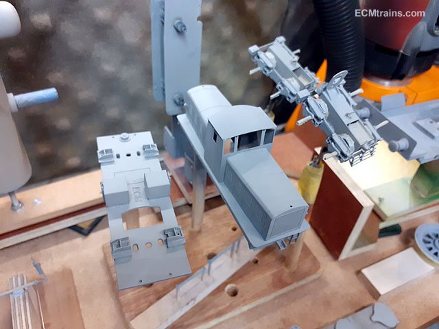
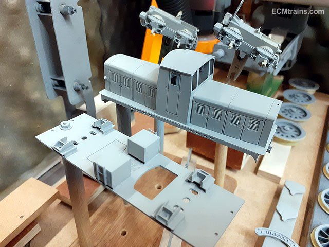
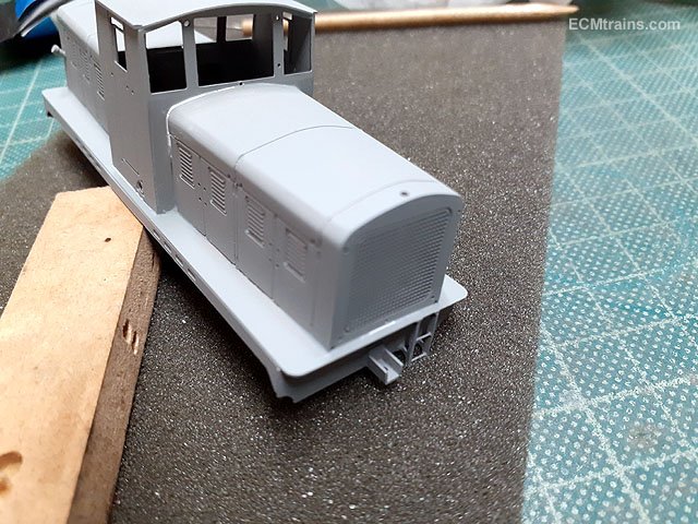
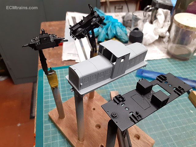
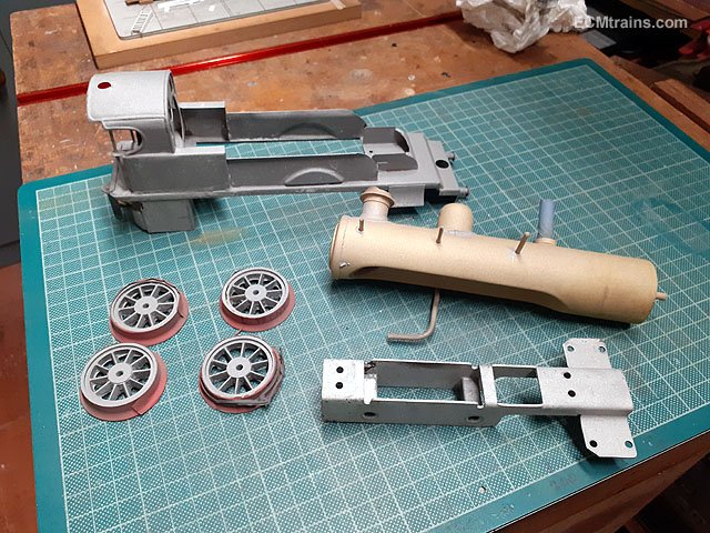
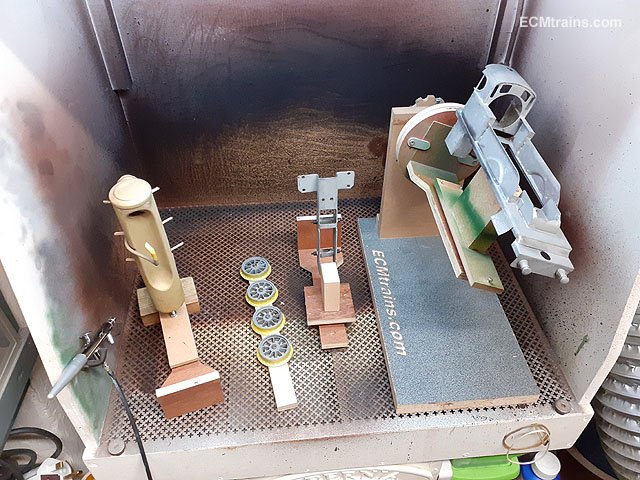
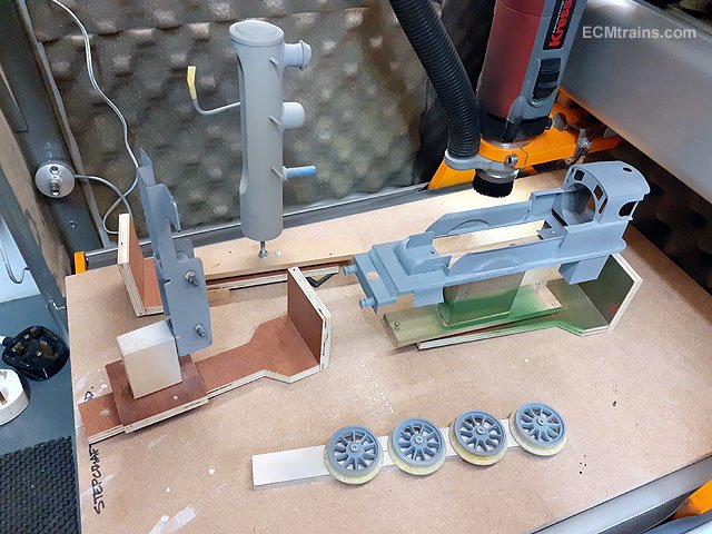
I started to add colours to the Walker last week. After a good clean down with W5 the bogies were masked up as the wheels are now fixed in and I did not want to paint them, the axles, and the drive gears in the motor bogie. All parts were stuck on sticks to hold in the hand while painting. First a very thin coat of etch primer. Slightly over did it on the body but it was very hard to spray into the detail without this happening- could still faintly see the brass underneath! First undercoat after leaving the etch primer sit for 2 days. Then a little bit of filling on the body and ready for a second undercoat. Second coat done and now for some colour. 2 coats of satin black to the chassis, bogies and coupling rods. Tomorrow the body will be green..... Eoin
- 136 replies
-
- 10
-
-

-
- class f
- west clare
- (and 1 more)
-
Not Kingspan but the same kind of thing for the baseboard deck;- This stuff cant be cut with hot wire, but if straight cuts like for the baseboard the carving knife is the one...... .........and this is some scenic work done in polyfoam and aroboard which can be cut with hot wire;- I reckon insulation and foam is the best material to use- easy to form, lightweight, and takes any finish except strong solvents! Eoin
- 1 reply
-
- 1
-

-
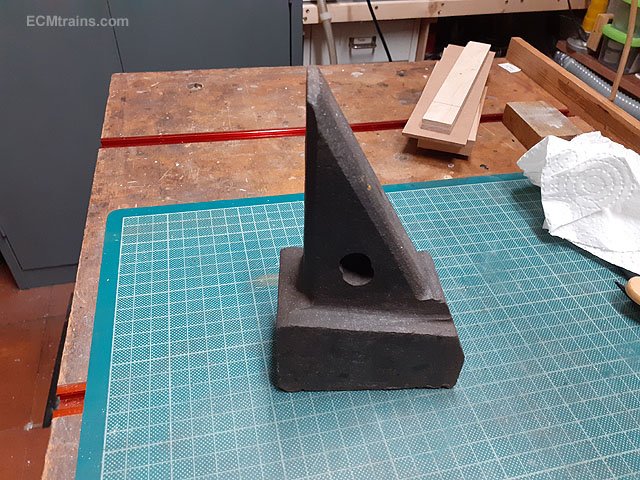
While on the subject! Here is a very handy modellers device which I use as an anvil from time to time Eoin
-
Cuisle na Tíre (“Ireland’s Transport Magazine”)
murrayec replied to jhb171achill's topic in General Chat
Mr. Fry built his Class 800 with that sign board on the smokebox door!
-
Bing Live Steam Loco Gauge O - Repair & Restoration
murrayec replied to murrayec's topic in ECM Model Trains
@Midland Man Yes I do like these locos, they do look charming sitting on the table or on the shelf, though another thing when the fire is lit and its trundling n spitting around a track! They come up on ebay and the UK model engineering websites if your interested.... Eoin- 24 replies
-
- 1
-
-
- bing live steam
- bing gauge o
- (and 1 more)
-
Lenz silver mini+ decoder with motor short error
murrayec replied to Imahilus's question in DCC, Electrics and Electronics
One thing that might be causing the problem;- Old GF Class 08s have a gear splitting problem! If a gear is split the bogie jams, the motor cannot run and maybe the controller sees that as a short! Check each bogie, generally the intermediate gear or axle gears are the ones that split. To check them its best to remove the bogie from the chassis and turn the wheels by hand or run the bogie on a cutting matt and see what happens?? Eoin -
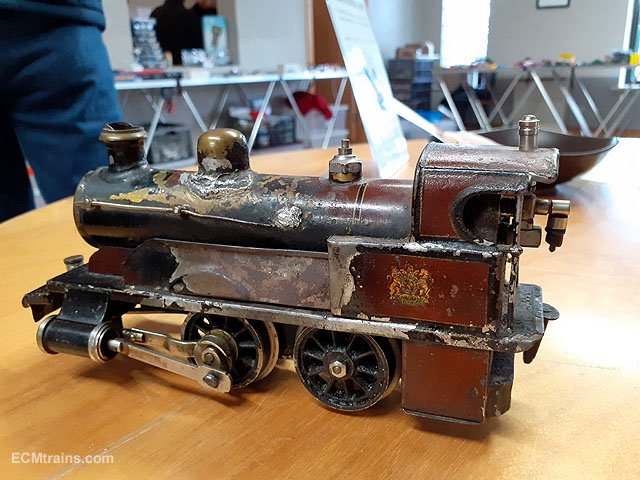
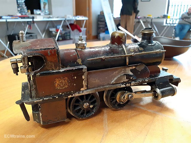
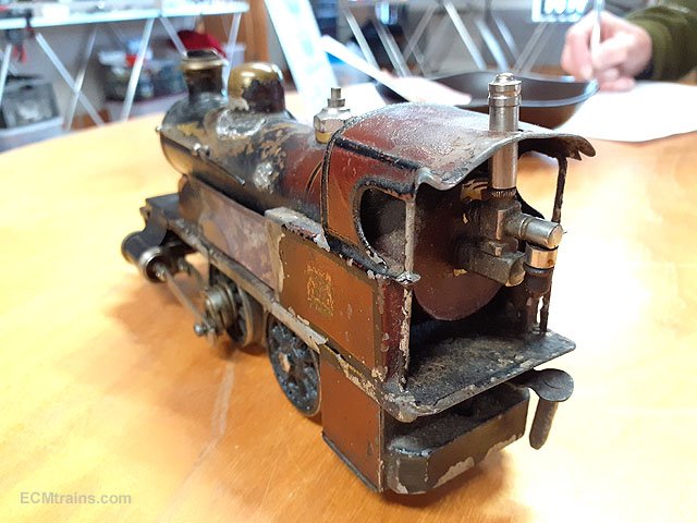
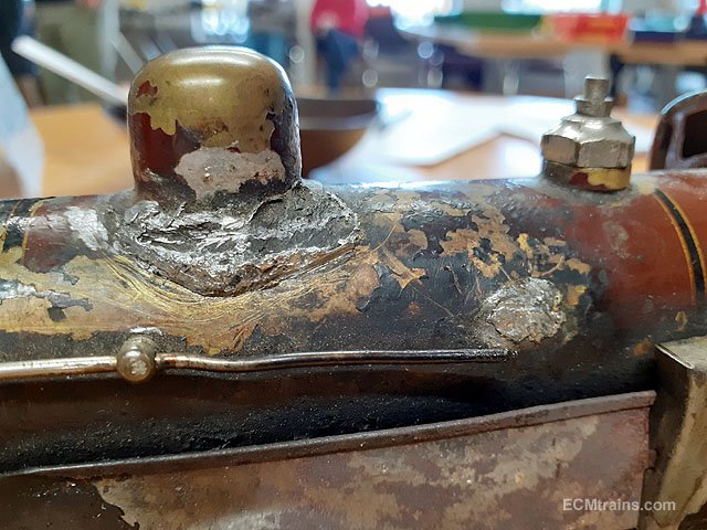
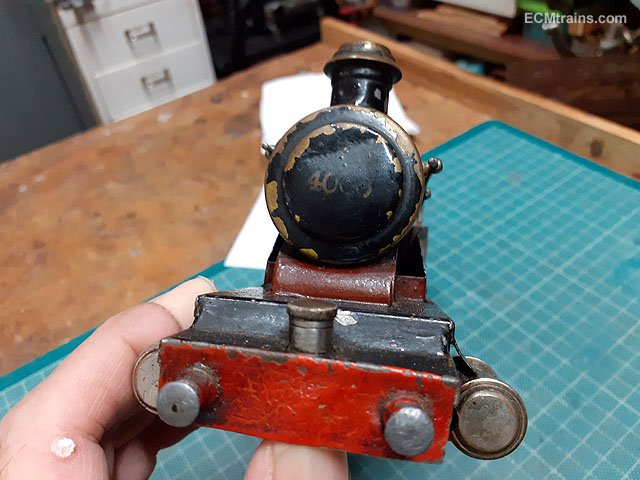
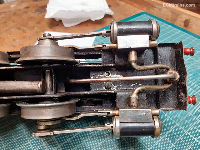
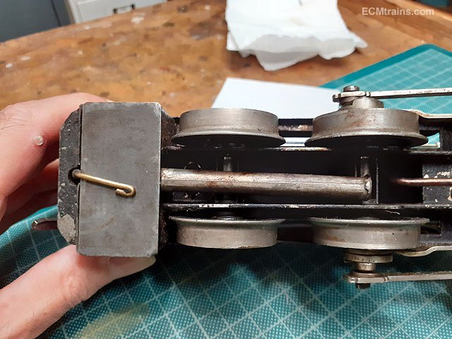
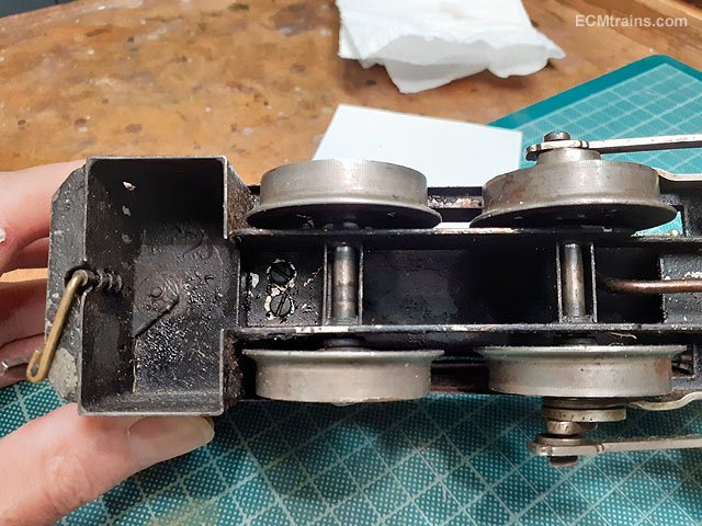
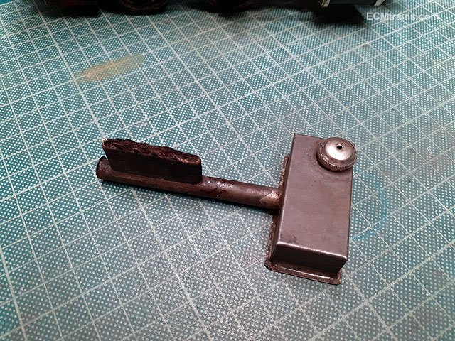
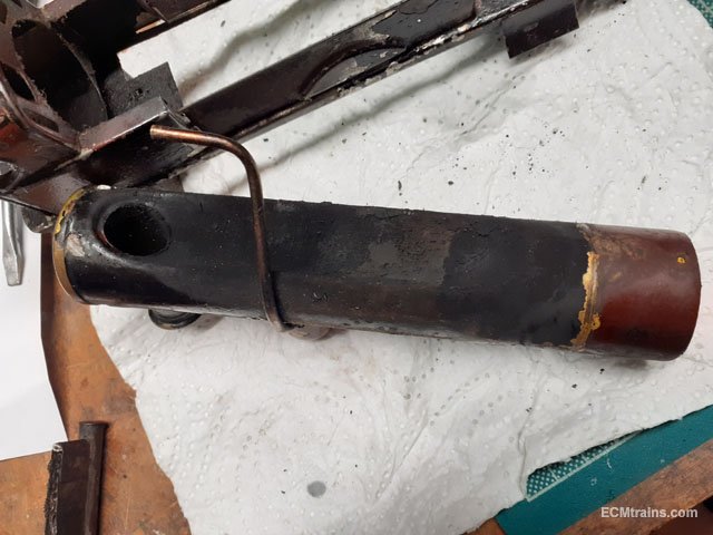
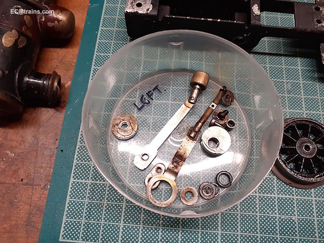
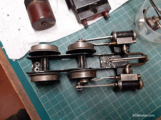
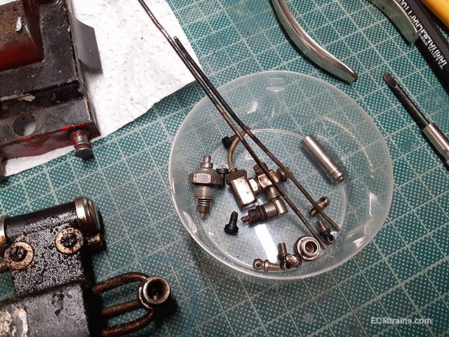
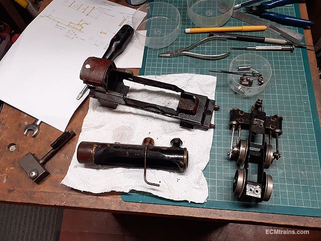
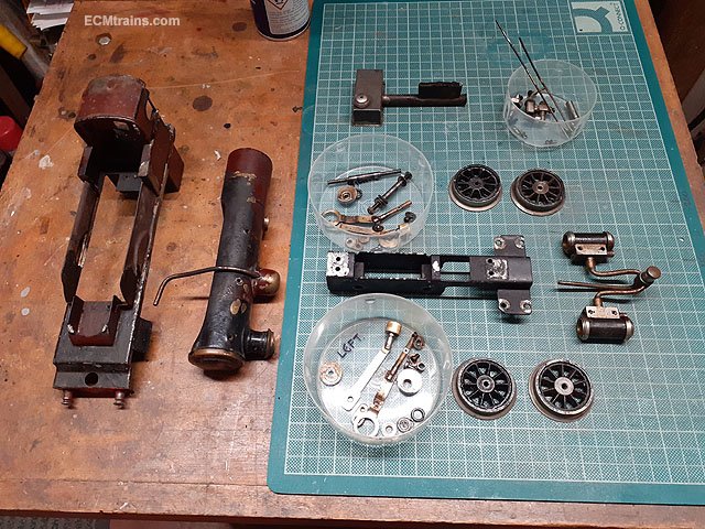
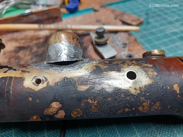
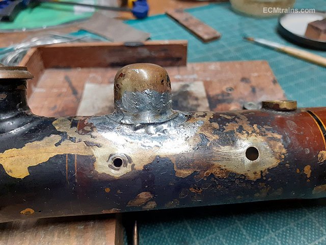
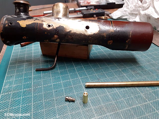
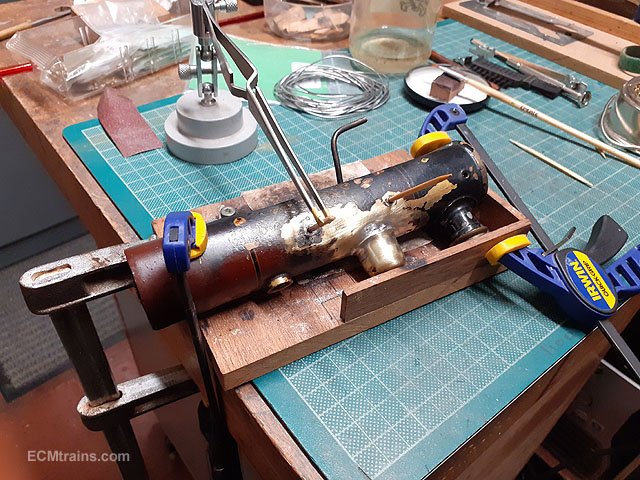
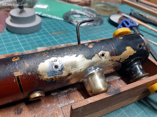
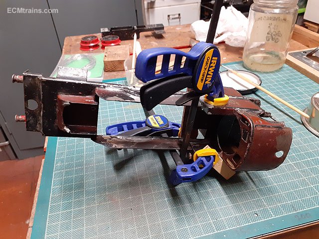
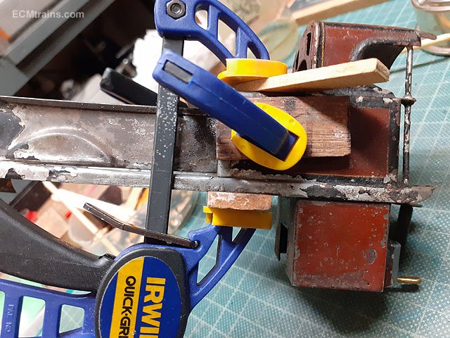
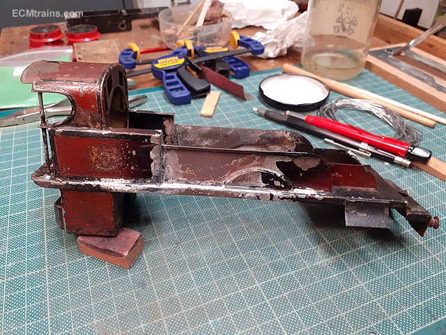
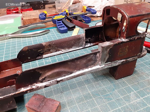
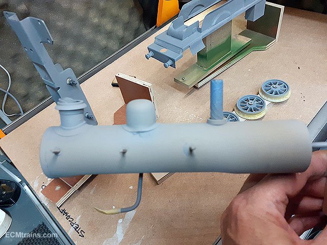
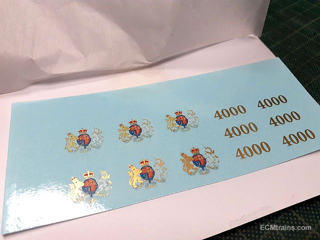
A rather sad Gauge O Live Steam Bing Loco came to the workshop for repair & restoration. It took a bang below the steam dome and some attempt was made to solder it up but to no avail, initially the client just wanted it repaired and asked could the paintwork be touched up! After consideration and the fact it has sentimental value, belonging to his farther and as a boy (client) he watched his Dad run it in the garden which gave both great joy- repair and repaint it! The loco will not be fired again when restored, it will be put in a case for display..... Not a level surface, all distorted n burnt, with a bang in the smokebox door. Chassis front mounting screw sheared. Burner in. Burner out. The burner. Inspection over the loco was stripped down. All the bits ready for cleaning up. After cleaning the dome was tackled first by removing that blob of solder to reveal a ding n crack- the ding in the boiler and the crack in the dome base. After cleaning off the solder blob I put on new solder, I used a piece of copper wire to fill the gap as the solder will not do that. Ready for a clean up- the remainder of the filling will be done at painting stage. Then a brass blank nut was turned on the lathe to be soldered into the boiler to replace the missing one. Jigged up for soldering the nut in, fingers crossed it doesn't fall in!! Done. Then a bit of horsing with sticks, bars, small hammer and appropriate shaped things to straighten the body up, once back close to shape all was clamped and soldered up. Worked out OK, a bit of cleaning up the solder after a blast.... .......blasted. Cleaned up and set up to start painting. Etch primed. A very light coat of etch primer was used so that one can see the metal underneath. Des in Studio Scale Models printed the decals from my artwork, he can now print gold! That's all for now..... Eoin
- 24 replies
-
- 5
-
-
-
- bing live steam
- bing gauge o
- (and 1 more)
-
Capt Bligh was also the man that stopped the Dublin chaps from building Dun Laoghaire harbour in Dalkey Sound- between the land and the Island they were going to build a wall across the sound on the Southern end so that ships could find a safe haven if they could not sail up the Liffey! Bligh pointed out the dangers of trying to sail into this design- massive rock coastal features and the Mugglands- a collection of rocks outside of the Island was a recipe for disaster! He proposed the location for the harbour where they eventually built it. He also addressed the Liffey silting up problem which could close the harbour use for months- first designing the diving bell which one can see today on the South quayside painted red, (Note;- I have since found information on the diving Bell, this is not Bligh's diving bell see further on in this thread for info March 2025), a mad contraption they floated out into the river, sank it, and then men went down into it to remove the silt. Needless to say they all got very sic and some died! He eventually came up with the Bull Walls idea- two walls extended out on both sides of the river into the bay to stop the bay sand being washed around the bay and silting up the river. He designed the structure of the walls to be movable on the sand as there was no rock to place a solid foundation. The structure was Oak blanks crossed over each other with a cannon ball housed in the crossover to allow flexibility, the structure was then filled in-between with hardcore to create the wall. Only the South wall was built like this, he left Dublin before the North wall was started, this wall was just constructed in rock dropped on the seabed and not as per Bligh's design. That wall is the reason North Bull Island exists, it's where all the sand swirling around the bay ended up after the North Wall was built.... Eoin
-
Nice photo wrennie, I spent many a summer day hanging out there and many nights in that shelter swigging bottles of Guinness, one thing back then was at about 11.30 or so every night the street lights were switched off- you would see Howth disappear, that switch thrown first and then the offing would walk-along to the pigeon house, Sandymount, Blackrock, behind us, and then Dun Laoghaire- darkness..... Eoin
-
The British Admiralty built the towers because they suspected & feared the French would use Ireland as an invasion point into England- attack on both sides. The Admiralty also harboured their ships mostly along the Irish coast to keep them away from French attack. Dublin Bay was the main harbouring point in Ireland and that is one of the main reasons for the 26 towers built on this coast- to protect Dublin and also as an early warning system to 'The French Are Coming', the Admiralty had a ship in Dublin on stand by at all times to set sail for England if the tower warnings went off, sailing across the Irish sea before the French made it up the coast to warn England 'The French Are Coming'. The first tower was at Bray Head South and with flags and fire the massage would reach Dublin in minutes allowing a quick getaway........ the system was never used- the French diden't come! The towers dotted around Ireland's other harbours and rivers were for the same reason but the warning system to Dublin was across land by horse. Eoin
-
@Georgeconna see back up a few posts where thumper asked the same question- build4less, don't know if they have a Cork outlet? Eoin
-
If the foam was orange it could have been Covid...... Eoin
-
Deadly stuff David Megapoints really is the business..... Eoin
-
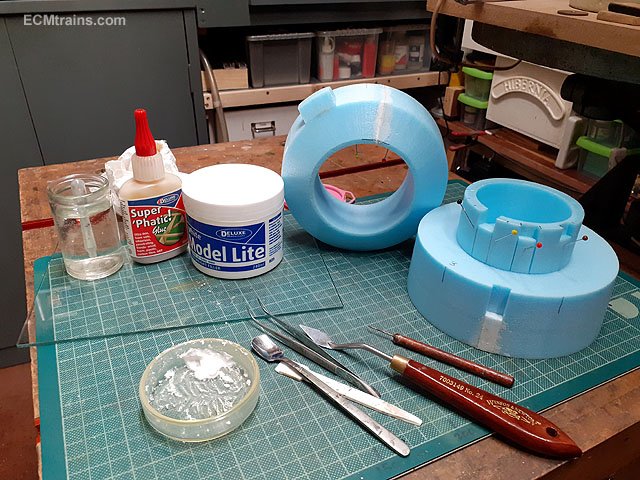
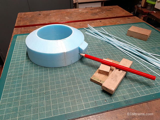
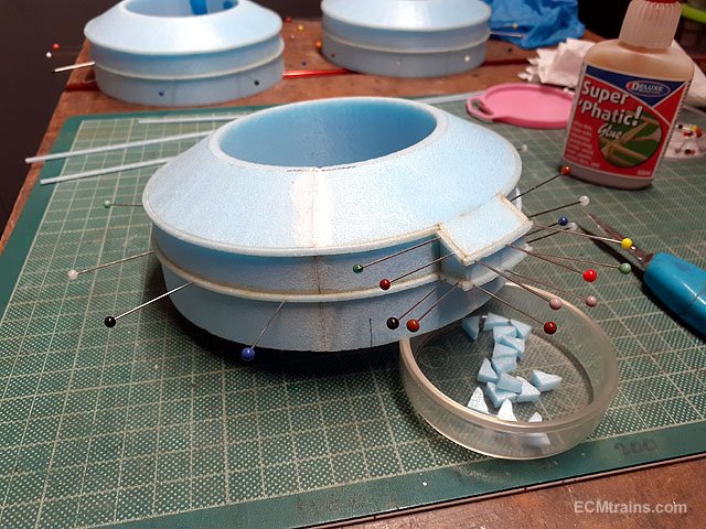
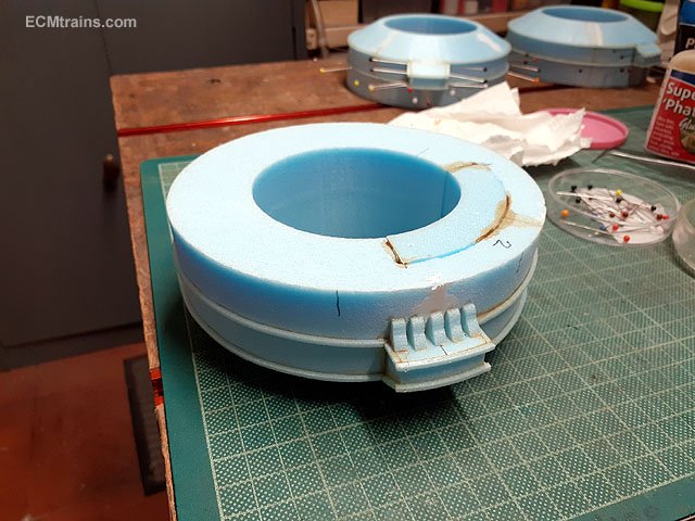
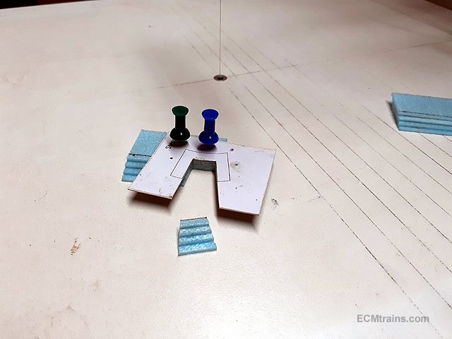
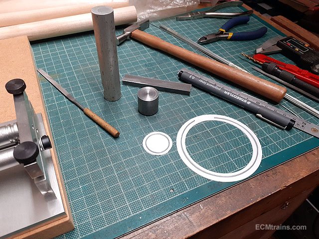
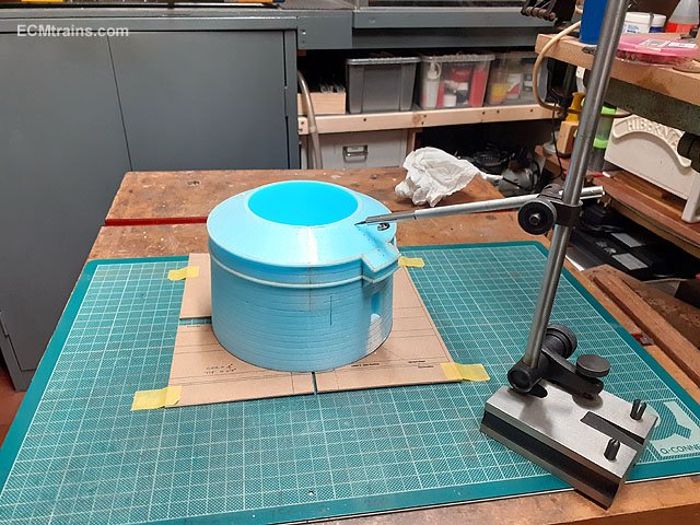
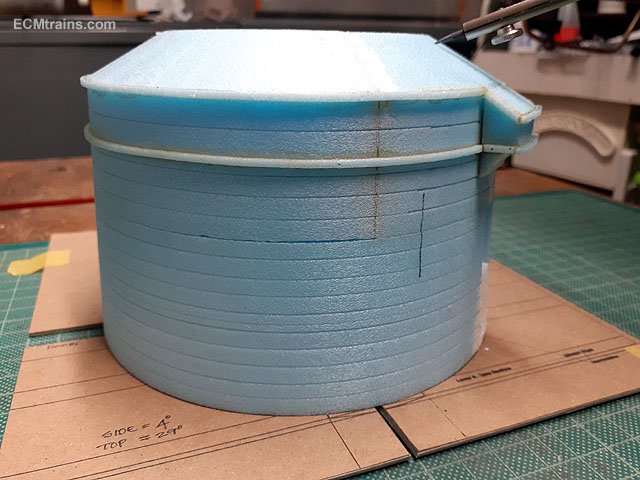
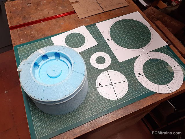
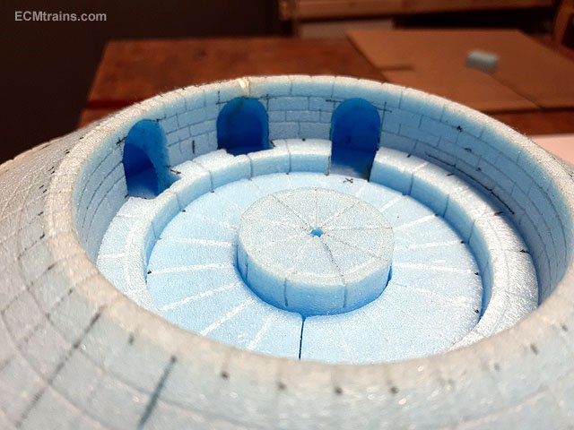
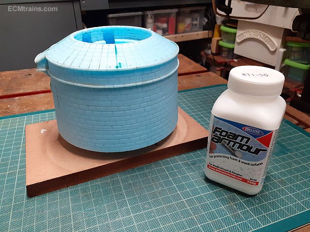
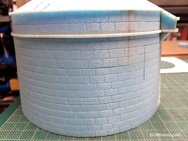
A bit of filling, sticking, n scoring the Martello Tower over the weekend! I used Deluxe lightweight foam filler to fix some of the through cuts and other bits. Filling dry and sanded the next bit of detail to the parapet was added, this photo is of setting up a guide line to stick on the detail. Detail on. The corbels to the machicolation being stuck on. Steps for the roof access being cut with a card template to guide the hot wire. I decided to forgo using the styrene racer detail I cut out earlier, I reckon the foam looks better for the granite appearance, so I bent up .8mm steel wire to make the racers which will be stuck down after they are painted a rusty colour. The photo shows using the styrene parts for sizing the steel wire. The upper n lower sections of the tower were finally stuck together and set up for scoring the stone coursing, done on the setting card with centre pin to rotate the tower and then marked the coursing with a sharp pencil lead on the height gauge. Horizontals complete. Verticals done by freehand. The radial scoring was done by making stencils from the drawing to mark off the divisions, five were needed in all. Coursing detail done. And finally a coat of Foam Armour is applied before starting to paint. A few more bits of filling is required in the rooftop gun platform area which will be done after the first coat of paint. Eoin
- 347 replies
-
- 10
-
-
Mountfleet Models 1/24 Clyde Puffer.
murrayec replied to Georgeconna's topic in Aviation & Maritime Modelling
Lovely stuff George, I like the scale and it's my preferable type of boat, it will be nice to see it running when finished.... Eoin -
@Midland Man You can get them here;- https://www.railtec-models.com/catalog.php?&type=5&gauge=4mm®ion=2&livery=203 Eoin
-
@burnthebox I reckon it's a BSA Bantam 175cc https://en.wikipedia.org/wiki/BSA_Bantam Eoin
-
-
Wrennie I have a Class C kit somewhere in the attic pile! Eoin
-
They scale 6'-9'' to 7' using the Expo Gauge OO Rule. Eoin
- 309 replies
-
- 1
-

-
- mgwr
- 21mm gauge
- (and 1 more)
-
@2996 Victor For six wheelers, Studio Scale Models do a pretty good and comprehensive kit Another link coming on and more reading for the weekend;- Eoin
- 309 replies
-
- 3
-
-
- mgwr
- 21mm gauge
- (and 1 more)