

Horsetan
-
Posts
2,296 -
Joined
-
Last visited
-
Days Won
4
Content Type
Profiles
Forums
Events
Gallery
Everything posted by Horsetan
-
I really like the portrayal of the cows in their field. Are they small, or far away....?
-
Aren't the Irish Mk.3s wider than the British ones? Or have I been misinformed?
-
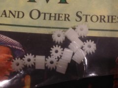
That's the cover of Maurice Walsh's "The Quiet Man (and other stories)". The next gear type to find is the big 20-tooth one, same 0.5MOD pitch. The axle centre distances for this one work out at 7.95mm.
-
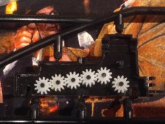
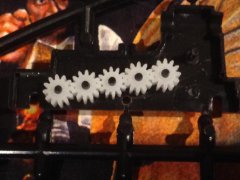
The gears fit straight into the Hymek gear casing: First thing to note is that the gear mesh is quite soft, and everything revolves loosely. But it's when you combine these Hong Kong cogs with the original Heljan ones, that you notice a slight difference: I've put one HK cog in the middle of some Heljan ones. Spot anything here? In fact, the HK cog has slightly thinner teeth than the Heljan, so the mesh is a little looser and, when combined / compared with Heljan, seems to have a marginally smaller overall diameter. It is so slight, yet makes quite a difference for the purposes of the experimental Sulzer bogie, because it means that the HK gear teeth do not impinge upon the space required for the new centre axle, and we really need to reclaim as much room as possible here. For anyone wanting to experiment with these generic 0.5MOD cogs, they are available from Hong Kong eBay seller "sellerbible". This particular pack cost just £1.49, and the seller does not charge for international postage, which I think is quite remarkable.
-
-
-
-
...and in the 1960s/70s, Fleischmann got into the act by making some models which turned out to be 1:82 or 1:85....
-
Bachmann Irish Station and Engine Shed
Horsetan replied to Paudie Riordan's topic in For Sale or Wanted
Ah, that clarifies things. -
Bachmann Irish Station and Engine Shed
Horsetan replied to Paudie Riordan's topic in For Sale or Wanted
Wasn't aware that Bachmann had produced Clonmel station. If it's the Carlow Station building (ref. 44-063A), it can be had brand new for about 25 Euro at the moment. -
UPDATE: The extra 12T gear pack is just after arriving from Hong Kong, so they'll be tried in the Hymek bogie casing later. On the face of it they look identical to the ones that Heljan themselves use, i.e. 6.9mm diameter over the tips of the teeth, 0.5MOD pitch, and may even be supplied by the same gear maker. Gear thickness is about 5mm.
-
Trix is alright. They seem to act nowadays as a sort of 2-rail outlet for Märklin.
-
If you're talking about the current generation of models, there's not a great deal to choose between them. Having said that, Roco seem to have much better spare parts support, and you can buy parts online direct from them.
-
West Caoast main Line shut for another month.
Horsetan replied to Broithe's topic in Letting off Steam
"...you wouldn't understand...." -
I can see this photographic in-joke running into the next century....
-
The Official Irish 'Might Have Beens' Thread
Horsetan replied to minister_for_hardship's topic in General Chat
In short, new engines with very little of the originals incorporated. Useful for accounting purposes. -
Sutton Locomotive Works Class 24 - D50000.
Horsetan replied to RedRich's topic in British Outline Modelling
The other selling point is that it's available as RTR P4. Price is at least £200, but if you want it badly enough, there's no other option. -
The Official Irish 'Might Have Beens' Thread
Horsetan replied to minister_for_hardship's topic in General Chat
The solitary P1 2-6-2T contained quite a few Woolwich parts - cylinders, parts of the motion, and driving wheels. -
There must be a serious degree of red ink on some profit and loss accounts.
-
And here's something similar - scroll about three-quarters of the way down the page after clicking the link.
-
I'm wondering what the 1916 memorabilia will be.
-
The Official Irish 'Might Have Beens' Thread
Horsetan replied to minister_for_hardship's topic in General Chat
...and not the Gresley variety, either. -
The Official Irish 'Might Have Beens' Thread
Horsetan replied to minister_for_hardship's topic in General Chat
Possibly the same one as in the Rowledge book? -
The Official Irish 'Might Have Beens' Thread
Horsetan replied to minister_for_hardship's topic in General Chat
More likely extension of the double track on the Cork Blackrock & Passage route. -
Careful now.