Horsetan
-
Posts
2,684 -
Joined
-
Last visited
-
Days Won
4
Content Type
Profiles
Forums
Events
Gallery
Blogs
Everything posted by Horsetan
-
Enjoy it. The postal strikes over here mean that you'll be lucky to get any post this side of Christmas......or New Year.
-
Ireland once had a number of 3ft narrow gauge lines - the central buffer was common.
-
"Chancers' Greed Thread" might cover many many retail sins.
-
What exactly was the design flaw that led to this happening?
-
I think a case might also be made for the Bazin "500" class 4-6-0s, as their splashers are but mere bumps in the footplate.
-
Boris seemed quite keen on Cincinnatus.....
-
I had to sit down for a moment when I saw what he wanted for a copy of the first MRJ Compendium.
-
 Probably OT, but did you manage to rectify the missing crankpin web in the post-1930 driving wheel in the end?
 -
I went to his oul shop in Stamford station years ago. He doesn't exactly undercharge.....
-
I'm amazed I can't hear the sound of cans being kicked.
-
The Official Irish 'Might Have Beens' Thread
Horsetan replied to minister_for_hardship's topic in General Chat
They weren’t the only ones, especially if they sensed they could get someone else to pay for it. -
Limerick to Foynes railway reopening plan
Horsetan replied to spudfan's topic in What's happening on the network?
Imagine the Healy-Raes getting involved.... -
...although nowadays, it's probably more brown than green because of decades of pollution.
-
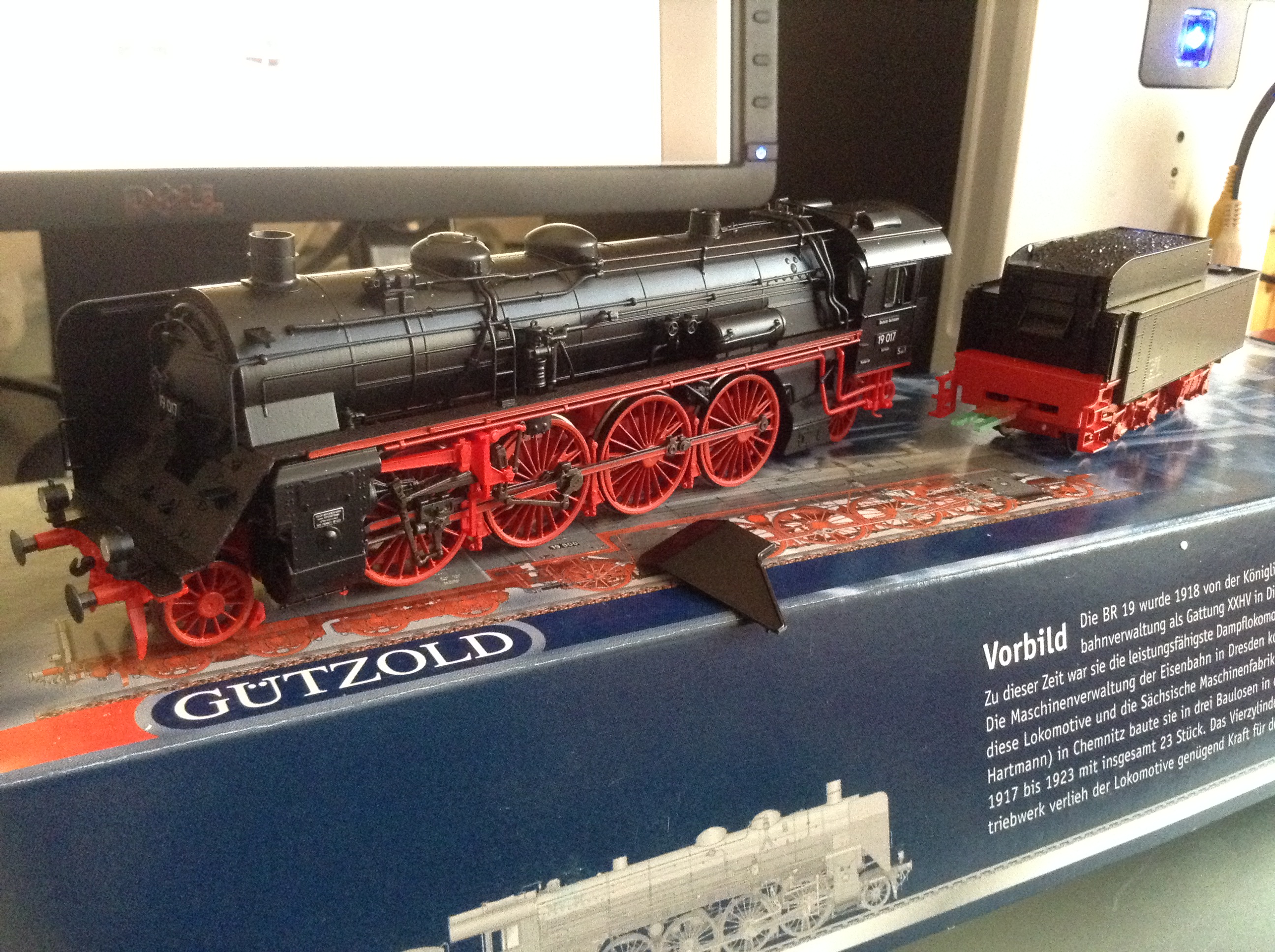
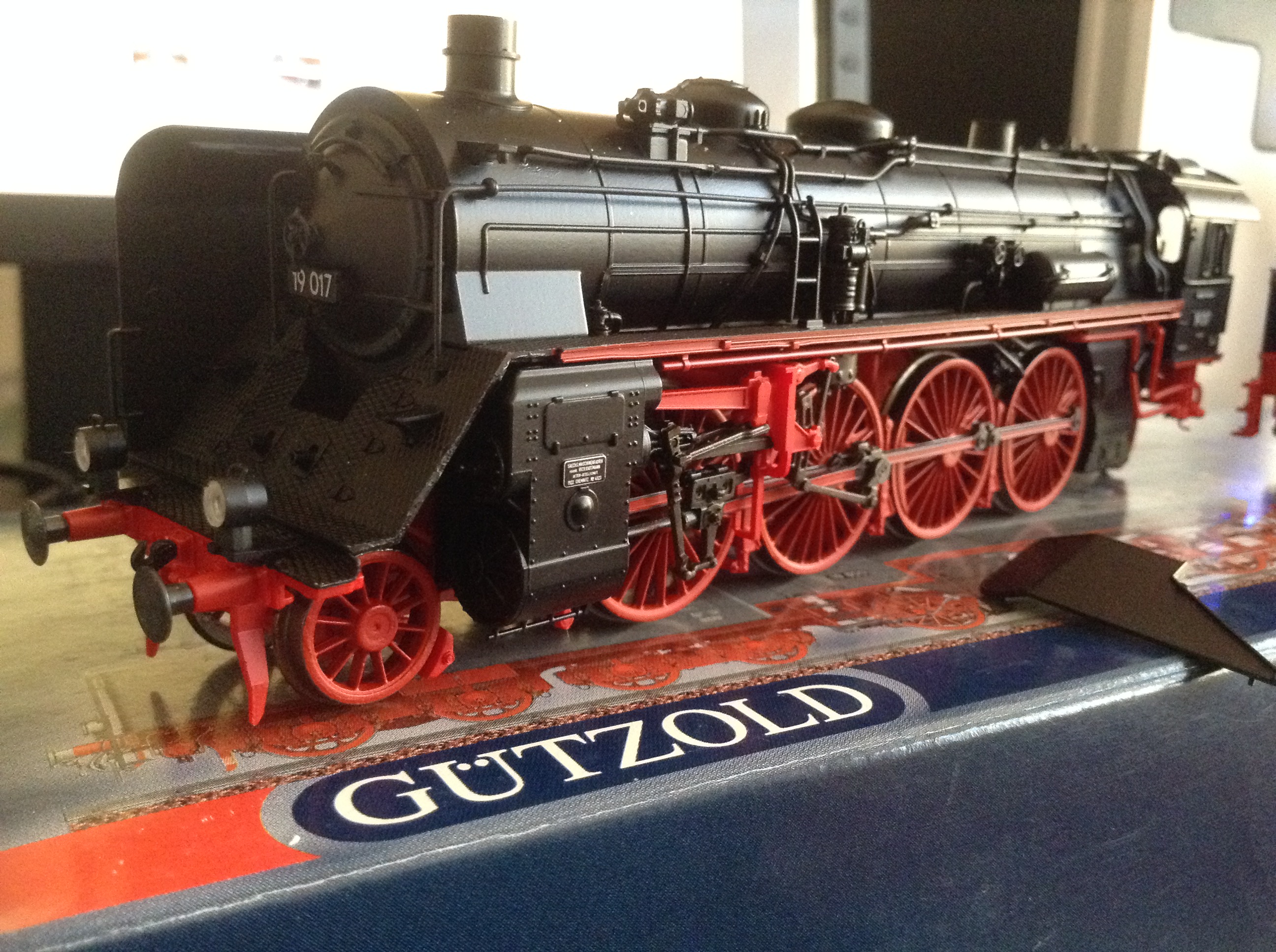
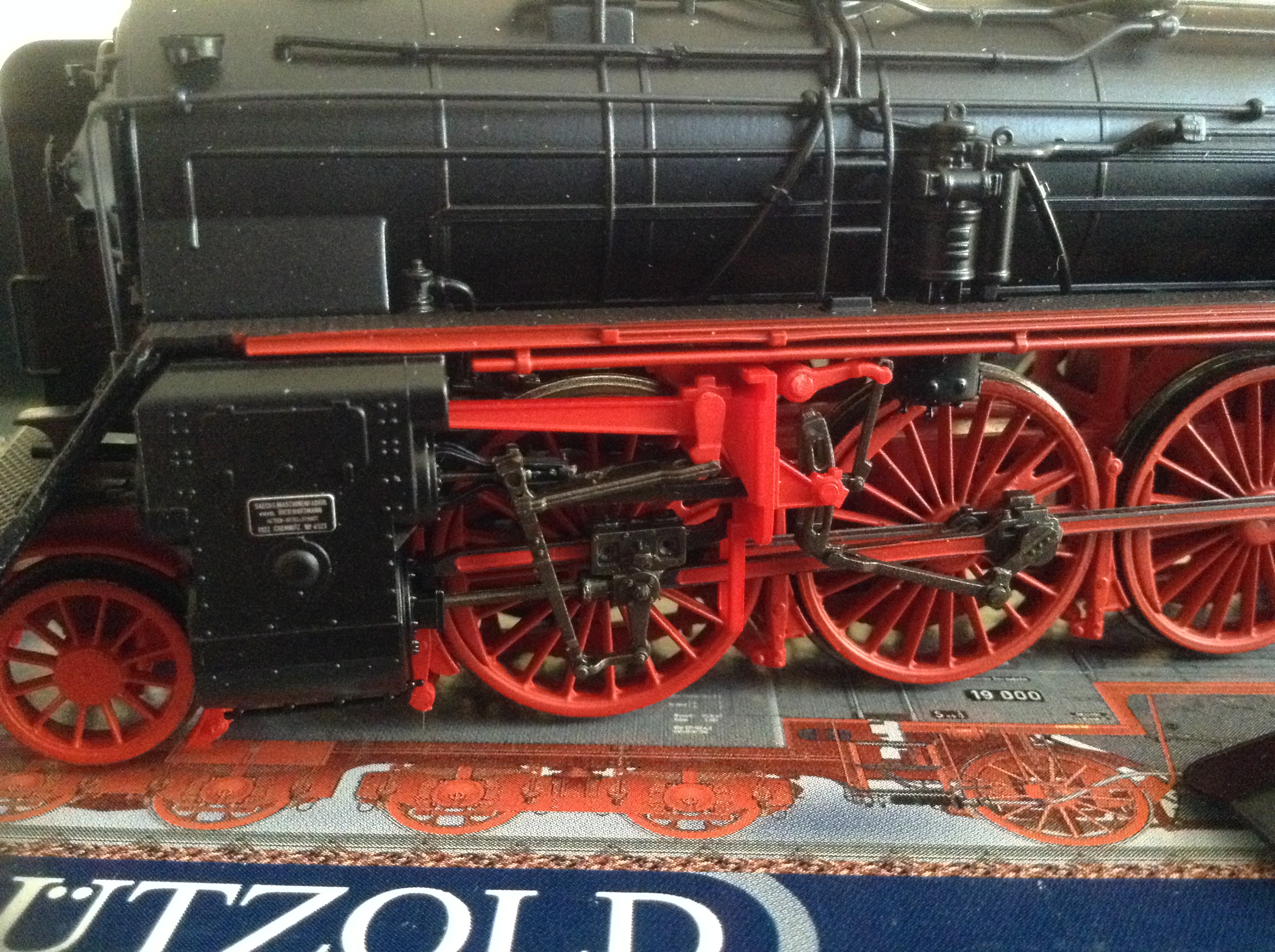
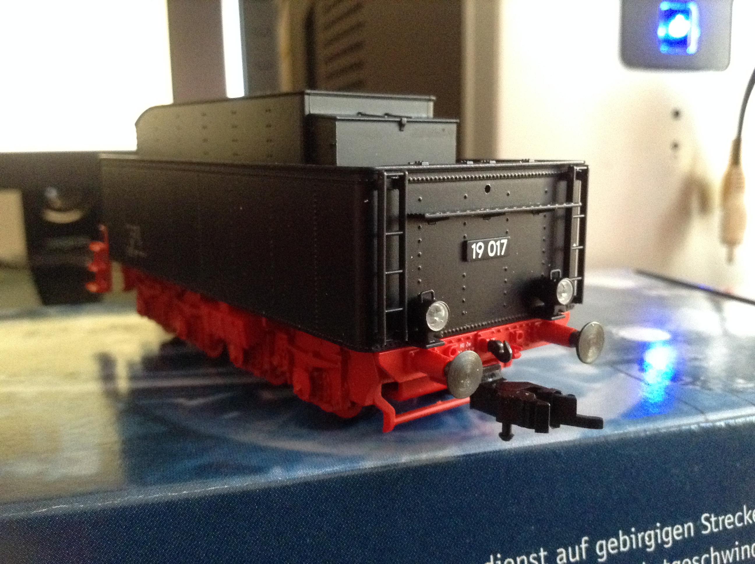
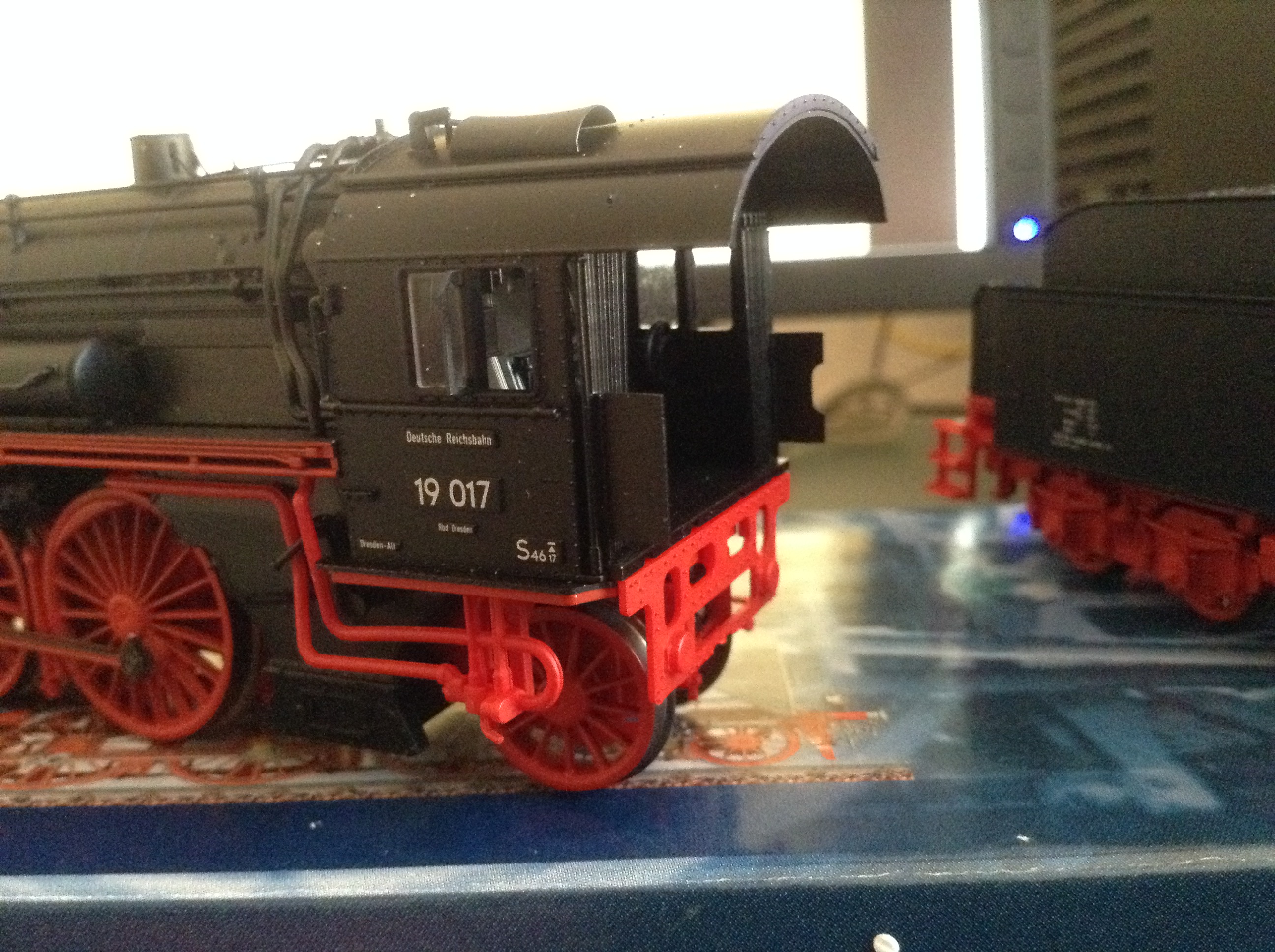
Et tu, Brute? Et tu? Actually mine does get a run now and then, and she has the extra tender for additional water capacity.... What you really need is a Br.45 2-10-2, and a Br.85 2-10-2T. Just those two are already a lot to look at. There's no reason for having German engines other than the fact that I like them, and occasionally they come up very cheaply on eBay. From 1926, they were up to 25 years ahead of Britain when it came to standardisation. Before the Wagner standard era, there were things like this Saxon XX HV 2-8-2. This model came cheap because - as the photos show - it was slightly broken, but it works. The real 19.017 still exists but has never steamed in preservation; it owes its survival to having been used by the Halle research facility as a brake test engine during the East German DR era, and is the only one (of three Br.19s kept by Halle) that escaped being massively rebuilt.

-
I got distracted and ended up reading the whole of that! The final article, Dalcassian Steam, was fascinating.
-
Their "O" gauge Gresley A3 and A4s don't seem to have sold like hot cakes. Wonder why that is....?
-
There's an outside chance of your coaches turning up before my order for five Irish driving wheel axles is completed by Ultrascale #eightmonths
-
For up-to-date authenticity, there should be a double-decker being driven along a pavement somewhere.....
-
IRM to model record breaking Swiss Rail 100 coach formation?
Horsetan replied to Noel's topic in Letting off Steam
I thought it was a real shame that the RhB weren't able to include some of their heritage, tourist, and loco-hauled stock in the eventual consist. -
I knew I should have bought that neon cross......
-
Would you model in 21mm if RTR track and models were readily available?
Horsetan replied to BosKonay's topic in Irish Models
I wonder if the software allows the whole chair (instead of the jaw) to be tilted to achieve the cant? -
Would you model in 21mm if RTR track and models were readily available?
Horsetan replied to BosKonay's topic in Irish Models
Anyone seen this Templot "PlugTrack" idea? It seems that this can work for 21mm gauge, although it won't give you the correct 1:20 canted rail. Bullhead only so far, not flat-bottom rail. -
Ernies Massive Irish 1930's to 2005 Photo Archive
Horsetan replied to Glenderg's topic in Photos & Videos of the Prototype
The last regular use of the branch was in 1948. Track lifting hasn't started here, but would have done by 1955 because that's when the girder bridge at Stranorlar was dismantled by Hammond Lane Metal Co. Incidentally, Hammond Lane feature so heavily in the records of scrapping railway infrastructure and equipment that I wonder if there was anything that they weren’t involved in cutting-up one way or another. -
British stuff from the Catacombs
Horsetan replied to jhb171achill's topic in British Outline Modelling
56 was just the service number for that route that day, so train number 56.