Tullygrainey Posted September 10 Author Posted September 10 Hunslett now has pickups. 31swg phosphor bronze wire shaped to hook over the wheel flanges at the top. Since @Northroader (I think) suggested this method somewhere a while ago, I've been using it and it works well. The hook keeps the pickup wire in place and there are two possible contact areas - wheel flange and wheel back - to keep things moving along. Each brake hanger has 2 bits soldered together. The RSU did this job very neatly Brake rigging is 0.45mm brass rod The whole nine yards - pickups, brakes and sand pipes. Phew! Trial run under DC at Loughan Quay. Bodywork isn't secured yet. IMG_5771.MOV Hardly any burnt fingers today Alan 9
Mol_PMB Posted September 10 Posted September 10 Very smooth! And it looks at home on the quayside. 1 1
Tullygrainey Posted September 10 Author Posted September 10 Just now, Mol_PMB said: Very smooth! And it looks at home on the quayside. Thanks. Does doesn't it!
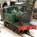
leslie10646 Posted September 13 Posted September 13 Tongue firmly in cheek. The modern version! At Spiez, Bern Lotschberg Simplon Railway. 1
Tullygrainey Posted September 13 Author Posted September 13 46 minutes ago, leslie10646 said: Tongue firmly in cheek. The modern version! At Spiez, Bern Lotschberg Simplon Railway. It’s very clean!
leslie10646 Posted September 13 Posted September 13 27 minutes ago, Tullygrainey said: It’s very clean! I'll look for a grubby one! 1
Tullygrainey Posted September 14 Author Posted September 14 (edited) Cleans up nicely does Hunslett But nothing like a coat of primer to show up where the filler needs to go. I must have squandered about half a mile of brass rod getting those handrails the way I wanted them. I'm never entirely happy mounting chassis with bolts front and back, given the chance that tightening both could twist the chassis. So this one has a bolt at the back and this little bit of bent 1mm brass rod at the front which locates into a slightly oversize hole in the front chassis spacer. Chips soon Alan Edited September 14 by Tullygrainey 5 1 1
Galteemore Posted September 14 Posted September 14 Very elegant solution Alan. Agreed - the fore and aft bolts can cause all manner of issues 1
west_clare_wanderer Posted September 14 Posted September 14 2 hours ago, Tullygrainey said: Cleans up nicely does Hunslett He's a very handsome little fella Alan! You've done a wonderful job (as always). He really looks at home in that setting too. 1
Tullygrainey Posted Tuesday at 13:02 Author Posted Tuesday at 13:02 (edited) There's a surprising amount of free space inside this Hunslett so a sound installation looked feasible. The sound chip was hardwired with all the joins covered with heat shrink sleeving. The speaker wires are connected to the chip via a mini-plug & socket arrangement which will allow the speaker to be permanently mounted and un-plugged if/when the chassis needs to come out. Testing the wiring. Despite a 50:50 chance of getting it right first time, I invariably wire the motor terminals the wrong way round so that it runs backwards with the controller set for forwards. Easily fixed but irritating. IMG_5818.MOV Yes, it all fits. The speaker is in the cab where the backhead should be (can't be seen) and the chip and stay-alive capacitor are in the boiler. IMG_5827.MOV Paint next. Alan Edited Tuesday at 13:05 by Tullygrainey typo 2 1
.png.c363cdf5c3fb7955cd92a55eb6dbbae0.png)
Recommended Posts
Create an account or sign in to comment
You need to be a member in order to leave a comment
Create an account
Sign up for a new account in our community. It's easy!
Register a new accountSign in
Already have an account? Sign in here.
Sign In Now