Tullygrainey Posted July 5 Author Posted July 5 Now I am inordinately proud of this. Four separate bits plus 3 bits of wire. Just a pity it'll be hidden away inside the cab. I'd like to solder it on the cab roof 2 3 3
Galteemore Posted July 5 Posted July 5 8 minutes ago, Tullygrainey said: Now I am inordinately proud of this. Four separate bits plus 3 bits of wire. Just a pity it'll be hidden away inside the cab. I'd like to solder it on the cab roof No definitely deserves a wagon of its own with spotlights and a theme song. Beautifully done 2
Patrick Davey Posted July 5 Posted July 5 (edited) 4 hours ago, Tullygrainey said: Now I am inordinately proud of this. Four separate bits plus 3 bits of wire. Just a pity it'll be hidden away inside the cab. I'd like to solder it on the cab roof Great - now I know who to call for my next signal box interior details........ Edited July 5 by Patrick Davey 3
Mol_PMB Posted July 5 Posted July 5 16 hours ago, Tullygrainey said: I changed the title of this thread rather than start a new one because what follows is more of the same really. After a fairly protracted period of building Irish locomotives of various persuasions and getting Kilmore, my BCDR exhibition layout up and running, I'm changing tack for a while and indulging one of my other interests - grubby little shunters, both steam and diesel. I've gathered a motley collection over the last few years with the intention of running them on an industrial themed layout which, to date, exists only on the back of an envelope. Anyway, here's the latest proposed addition to the roster. The kit consists of a single brass etch, some resin castings and all the necessary bearings, nuts, bolts and handrail knobs. Just add wheels, gearbox and motor. The chassis can be built rigid, compensated with all axles floating on pivoting beams or compensated with one fixed axle and hornblocks on the other two. Using hornblocks is my usual route and I intended to do that with this one before changing tack to try out pivoting beams. With hornblocks, the coupling rods are used as jigs to set the wheelbase correctly and so they get made first. Using the rocking beams method, the etched beams set the wheelbase so the rods aren't needed at this stage (the instructions don't mention making them until near the end of the build). However, old habits die hard... Chassis frame and rocking beams, pivoted in the middle, to hold front and middle axles. The beams for the rear axle aren't in the photo. Drive will be to the middle axle. A check after the event to make sure the wheelbases match the rods. I couldn't shake the notion that they mightn't! Chassis more or less complete. The vertical plate at the rear axle position is a knife edge on which the axle will rock. Footplate taking shape with baseplates for smokebox and cab. The 14BA nuts are captive, soldered to the plates so the body shell can be dismantled for painting. Lots of Vaseline under the plates and on the threads of the bolts to stop solder going in the wrong place and locking things up. it still did anyway once or twice, necessitating unseemly language, recovery and burnt fingers, in that order. The Resistance Soldering Unit came in handy to add the cab spectacle frames with a minimum of solder And this is as far as we got before bad light and the World Cup stopped play. More soon, Alan I’m looking forward to seeing this come together. You’re much better at finishing things than I am! 1
Railway Lyons Posted July 5 Posted July 5 8 hours ago, Tullygrainey said: Now I am inordinately proud of this. Four separate bits plus 3 bits of wire. Just a pity it'll be hidden away inside the cab. I'd like to solder it on the cab roof Stunning but of work. Maybe plant one at a yard point to be admire in the open? 1
Tullygrainey Posted July 7 Author Posted July 7 Sometimes when soldering, no clamp does the job better than your fingers. There is a small price to pay for this though 1
Tullygrainey Posted July 7 Author Posted July 7 More Hunslett. The cab is well on the way now. Trial fit of the usual High Level gearbox, a RoadRunner + for this one. Gibson wheels on order. Boiler next. Laminating layers for the smokebox is always a challenge - four layers in this case if you count the boiler. Getting enough heat into the thing and keeping it neat and tidy takes time and patience. There's always work for the fibreglass pencil when the soldering is done. Thanks to the smokebox front plate not seated properly and the difficulty of wrapping each layer tightly, the final wrapper came up short. Rather than dismantle the whole thing and start again, I've added small strips either side to bridge the gap. Not ideal but better than a space. The sand boxes will hide this to some extent anyway. I might have another go at it tomorrow. 10
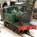
Tullygrainey Posted July 9 Author Posted July 9 (edited) Gibson wheels have arrived. The Hunslett is a pretty diminutive loco and the boiler diameter is only 16mm in model form. The High Level coreless motor I was intending to use fits inside ok but would require hacking lumps out of the bottom of the boiler at the back to get it in there when mounted in the chassis. To minimise the amount of surgery needed (I hope), I've ordered a smaller motor. So job parked for now. Here are a couple of the locos already on the grubby shunter roster - a Sentinel 0-4-0 Vertical Boiler steam engine and a Thomas Hill rebuild of the Sentinel into a Vanguard 0-4-0 diesel. Both built from RT Models kits. High Level 4wd bogies and Mashima motors. Edited July 9 by Tullygrainey 9 1
Tullygrainey Posted July 23 Author Posted July 23 Some progress with the Judith Edge Hunslett 14" kit. The saddle tank was tricky to keep square and took ages to do. Annealing the metal made it easier to roll. A number of goes to get those little steps - one each side - to solder securely. Trial fitting of the tank. It's just wedged in place. The instructions suggest weighting it so I'll put some lead in there though it might be somewhere to stow a decoder. There's precious little space elsewhere. Wheels are tiny - 13mm diameter this scale. The usual struggle to get the crankpins in straight seemed even harder with these for some reason. Having fitted running plate supports and brake hanger cross shafts to the chassis (not to mention painting everything), I realised they'd prevent my GW Models wheel press from being used. I find that more reliable than trying to quarter the wheels by eye so all that stuff had to come off again. In the process, 3 of the four guard irons let me know they weren't firmly attached either Once wheeled up the rolling chassis moved freely under finger power which is always an encouraging sign. A High Level Iron Core motor fits better than the coreless one but it's still a squeeze. The gearbox has to be tilted backwards, as in the photo and fed into the boiler. First runs on the rolling road weren't great. A tight spot and weird things happening with the middle axle. But after pickups were fitted on the front and middle axles, things improved. First tryout on the shuttle plank. IMG_5447.MOV Seems to run ok without pickups on the rear axle so I might not bother with those. We'll see. Brakes next - I decided it would be easier to fit the brakes round the pickups than vice versa. Alan Two more from the shunter roster - a pair of Hibbert Planet diesels of very different construction. On the left a whitemetal body kit from Roxey Mouldings on a High Level 4wd bogie. Weighs a ton! On the right a Planet Industrials kit - 3D printed body shell with nickel silver overlays and a 3D printed chassis. 8
Mol_PMB Posted July 23 Posted July 23 I love your Planets! This, 95% finished, has been sitting in my cabinet for several years. I never have been good at finishing things… Planets of this ilk are lovely to drive! 4
Mol_PMB Posted July 23 Posted July 23 Mine (in 7mm scale) is a Taff Vale Models etched nickel silver kit. The prototype initially worked at Weaste (about 3 miles NE) and later at Cadishead (about 4 miles SW) so I consider it a local machine. It then migrated to Preston (a bit further afield, but still Lancashire). 1
Tullygrainey Posted July 30 Author Posted July 30 The Hunslett gets brakes. What a fiddly job. Half way through. Rigging is 0.45mm brass rod. Easier to cut things over length and trim back after the soldering is done. No short circuits. Yay!! Some lead weight tucked between the frames front and back. There's more lead secreted in the saddle tank too. Since the boiler is largely covered by the tank and won't be seen, there was nothing stopping me from cutting lumps out of the top. So I did. More elbow room for the motor/gearbox which is mounted on a floating axle and needs to move about a little bit. Pickups fitted (31swg phosphor bronze wire) with flying leads... ... and a chip hardwired into place - a Layout Concepts (DCC Concepts as was) ZN8H.2 with the 8 pin plug cut off. It's a fairly tight squeeze but it works ok. The blue, black and white wires are intended for a stay-alive but I doubt there'll be room for one. The smallest I have just fails to fit inside the smokebox or anywhere else for that matter so I may just trim those wires back. More work still to do on the bodywork, including adding all the resin cast bits but it's always encouraging to get the little beast running. It'll also need a good scrub before any paint goes on! Alan 4
Tullygrainey Posted July 30 Author Posted July 30 (edited) Two more shunters from the roster, these with Irish connections. H&W Harlandic 0-6-0 DM in its final UTA days and a Ruston and Hornsby 0-4-0 DM, a nod to the ex-CSE loco currently with the RPSI at Whitehead. Both built from Judith Edge kits. If you're wondering why the the 3-link couplings on the front of the locos are defying gravity, there's an uncoupling magnet under the track just there Edited July 30 by Tullygrainey 7
Tullygrainey Posted August 2 Author Posted August 2 (edited) Hunslett is just about ready for paint. Tank not quite seated properly in these pics. IMG_5507.MOV Another one from the roster. A Drewry diesel with a High Level chassis kit under a Dapol plastic kit body with extra detailing. Mashima motor, Gibson wheels. Edited August 2 by Tullygrainey 8 1
Tullygrainey Posted August 9 Author Posted August 9 Hunslett just about done, bar a crew and coal load IMG_5559.MOV 2 5
Mol_PMB Posted August 9 Posted August 9 What a great looking loco, and a beautiful model that captures a 'work-worn but cared for' appearance. Lovely work! 1 1
Tullygrainey Posted August 18 Author Posted August 18 Another Hunslett shunter on the bench, an 0-6-0 side tank from CSP Models this time. Like the Hawthorn Leslie that began this thread, it's a 4mm version of a former Agenoria 7mm kit. Superstructure in brass with some very fine lost wax brass castings, chassis in nickel silver. Everything needed to build the kit is here which saves shopping around - various gauges of wire and rod, handrail knobs, even copper clad strip for pickups. Couldn't ask for more. Wheels from Gibson, gearbox from High Level. The supplied motor looks like ones I've seen on the Tramfabriek website. Gearbox is a Minispinner+, a recent addition to the range and a new one on me. It's a cut down version of High Level's RoadRunner Compact+ which takes up even less space. There are two sets of frames and two sets of coupling rods to choose from, allowing different versions to be built. Just as well because I destroyed one of the rods (broke an end off - does this sound familiar?) while soldering up the laminations so had to use the other set. Managed to get those done without further mishap. The instructions describe a rigid chassis with drive to the middle axle but I'm building it compensated with drive to a fixed rear axle and hornblocks on the other two. The frames have half-etched lines to help get the cutouts in the right place. A compensation beam will be needed so that's been made from two thicknesses of scrap nickel silver etch. With its edge touching the two axles, a pivot point is drilled through it and into the frames. Frames ready for assembly and the compensation beam tidied up. Enough for one day. More soon. Alan 3
jhb171achill Posted August 18 Posted August 18 On 7/7/2026 at 9:30 PM, Tullygrainey said: Sometimes when soldering, no clamp does the job better than your fingers. There is a small price to pay for this though This day I burned my finger whilst doing battle with a GSR carriage bogie.........! 1
Tullygrainey Posted August 18 Author Posted August 18 1 hour ago, jhb171achill said: This day I burned my finger whilst doing battle with a GSR carriage bogie.........! And I hope you won! Go for it JB. No pain, no gain 1
Tullygrainey Posted August 20 Author Posted August 20 More Hunslett 0-6-0T. Compensation beam reamed for a bit of 0.7mm ID brass tube which will fit between the frames and pivot on a length of 0.7mm brass rod. One of the chassis spacers needed a bit cut out of it to clear the compensation beam Tabs and slots on the frames and spacers made the job of erecting the chassis easier. Soldered up on a sheet of glass to help keep it square and reduce the chances of ending up with a warped chassis. Bearings soldered in for the fixed axle. Frames, hornblocks (from High Level), compensation beam and coupling rods. All the ingredients for a compensated chassis. Bad light stopped play. More soon. Alan 2
popeye Posted August 20 Posted August 20 I know nothing about hornblocks but, If they move up & down could you do without the compensation beam?
Tullygrainey Posted August 20 Author Posted August 20 (edited) 2 hours ago, popeye said: I know nothing about hornblocks but, If they move up & down could you do without the compensation beam? No Patrick. Without the beam, the bearings would just ride up to the top of their travel in the hornguides under the weight of the loco and the loco wouldn't sit level. In the case of this chassis which has the fixed axle at the back, it would sit nose down. When stationary, the beam holds the two floating axles at the same height as the fixed axle but because it can rock around its central pivot, it also allows the wheels to move up and down and maintain good contact with the track on the move, hence compensating for any undulations. As one wheel moves up over a bump its partner at the other end of the beam moves down to stay in contact with the track. On a rigid chassis, one wheel going over a bump will lift other wheels off the track as it does so with detrimental effects on electrical continuity. Hope that makes some sort of sense. It's hard to describe. It's actually based on the principle of the three legged stool which never rocks because all the legs are always in contact with the ground no matter how irregular. In this compensated chassis, the three 'legs' are the 2 bearings of the fixed axle and the fixed pivot of the beam. Here endeth the tutorial! Cheers Edited August 20 by Tullygrainey 1 1
popeye Posted August 20 Posted August 20 Thanks Alan, That makes sense, now I know more about hornblocks 1
Tullygrainey Posted August 23 Author Posted August 23 Getting the hornblocks in the right place using the coupling rods as jigs. Half way through the job. Trial fitting the compensation beam And it all sits level. Yay! Ready for a clean-up and some paint 2 1
Tullygrainey Posted August 26 Author Posted August 26 (edited) Some progress with the Hunslett. I've shunted the chassis into a siding for a bit and done some work on the superstructure to get a better idea of how the gearbox will fit. Or not. Running plate first... This little beastie has a lot of rivets which took a while to press out. The larger ones on the cab were done by hand-feeding the etches into my trusty GW Models rivet press. For the small, tightly spaced ones on the tanks, I used a centre punch, probably my most versatile tool. It also gets used to scribe lines, scribe stonework into DAS clay and, now and again, to centre punch metal for drilling The usual tricky edge to edge soldering to get the cab erected. However, the bits are tabbed into slots in the running plate which is a real help in keeping things square. Beginning to look the part. The kit provides quite a lot of detail for the cab interior. Deciding in what order to add things and getting it all into place was a challenge, with all the usual elements of bad language, burnt fingertips and solder in all the wrong places.... ... but got there in the end. On my tidy, well laid out workbench. A place for everything and everything out of place. Boiler next. Alan Edited August 26 by Tullygrainey typo 4
Tullygrainey Posted August 26 Author Posted August 26 I do believe it is. Thanks for sourcing the photos.
Mol_PMB Posted August 26 Posted August 26 6 minutes ago, Tullygrainey said: I do believe it is. Thanks for sourcing the photos. Those are ones in my collection where I acquired the original negs/slides. But I have more of the Hunslet 'Jazzers' that I don't own copyright for, if you need specific views. MSC Railway is my other speciality...
Tullygrainey Posted August 26 Author Posted August 26 What's the location for the ones above? The road vehicles in that last one also caught my eye - there seems to be a line-up of MGBs and/or Midgets.
Mol_PMB Posted August 26 Posted August 26 4 minutes ago, Tullygrainey said: What's the location for the ones above? The road vehicles in that last one also caught my eye - there seems to be a line-up of MGBs and/or Midgets. They are all around Manchester Docks - New Barns area. The cars will be waiting to be exported. More in the same area, different photographer and date: I found a few more negatives I'd scanned but not yet uploaded to Flickr which also feature the Hunslets... 2 1
Tullygrainey Posted September 6 Author Posted September 6 More Hunslett. The boiler came pre-rolled and also had a cutaway to clear the gearbox/motor. It just needed tightened and seamed. Adding the smokebox was the usual struggle to get sufficient heat into the job. The front sandboxes are complicated little items but BluTack and brass rods held everything together for soldering. The rods were then trimmed back. High Level Minispinner gearbox checked for any glitches. Worm gear was fouling the final drive cog causing clicketty running so it got moved up the motor shaft a fraction which cured the problem. Smooth as silk now. Not sure how much welly these little can motors have but we'll soon see. Crankpins fitted to wheels and for once I think I got them all in straight. It's worth spending time on these, countersinking the hole at the back of the wheel and thread-locking the pins. I've had crankpins wind themselves out before now, meaning the wheels had to come off again to fix it. The axle holes in the wheels also get countersunk and the axle ends chamfered before the GW wheel press does the job of fitting and quartering the wheels. What a brilliant device! Rods on and a little reaming of the holes to get rid of tight spots. Rolls freely under finger power. Another bridge crossed! Lots of detail still to add but it's beginning to look like a loco. The tanks are full of lead. The boiler is just trial fitted for now. I'll have to confront pickups soon Alan 4 2
Tullygrainey Posted September 8 Author Posted September 8 (edited) I've always found cab roofs difficult. Should they be removable or not. If you solder them as the instructions for this kit suggest, it can make painting the inside of the cab or adding a crew difficult/impossible. If you paint first, then soldering becomes difficult with the possibility of damaging the paint. The way this particular kit has gone together, soldering from the inside isn't possible anyway so in this case, removable looks like the better option. I have used clips on some locos in the form of springy wires soldered at each corner on the underside of the roof. These slide into the corners of the cab and hold the roof in place. It's effective but tricky to do well and mine are not always entirely secure. I've lost count of the number of times at exhibitions I've noticed daylight showing between cab top and roof. I've also used the following slightly more secure solution on some builds. A strip soldered across the cab at roof level, either front to back or side to side contains a captive nut. A hole in the cab roof allows a bolt (14BA c/s in this case) to screw into this pulling the cab roof down tight. The bolt head is then concealed by a dummy ventilation hatch BluTacked or Tacky Waxed in place. I know these Hunsletts didn't have cab roof hatches - there are ventilation flaps front and back of the cab - but mine had one fitted after the loco was bought from the MSC by the well known (to me anyway) Belfast engineering concern of Sprocket, Layshaft and Moonshine Ltd for use in their private sidings complex. Well, it's my railway Alan Edited September 8 by Tullygrainey 6 3
.png.c363cdf5c3fb7955cd92a55eb6dbbae0.png)
Recommended Posts
Create an account or sign in to comment
You need to be a member in order to leave a comment
Create an account
Sign up for a new account in our community. It's easy!
Register a new accountSign in
Already have an account? Sign in here.
Sign In Now