murrayec
-
Posts
2,775 -
Joined
-
Last visited
-
Days Won
70
Content Type
Profiles
Forums
Events
Gallery
Blogs
Everything posted by murrayec
-
'Traction Maintenance Depot'
-
@Colonel I agree with irishthump, you would only need a starter DCC controller for your layout. There are plenty about for around 70 to 150 pounds second hand or new. I use the Roco Multimaus which would be fine for starting off, easy to use, then later as you get to grips with DCC you could upgrade.... Also, I recommend this book by Crowood Publishing, it is a great introduction to all aspects of DCC. It covers setting up the layout, discusses the types of controllers and chips, and gives plenty of examples of converting locos to DCC with loads of photos;- Eoin.
-
until
-
The August Fair Date;-

-
-
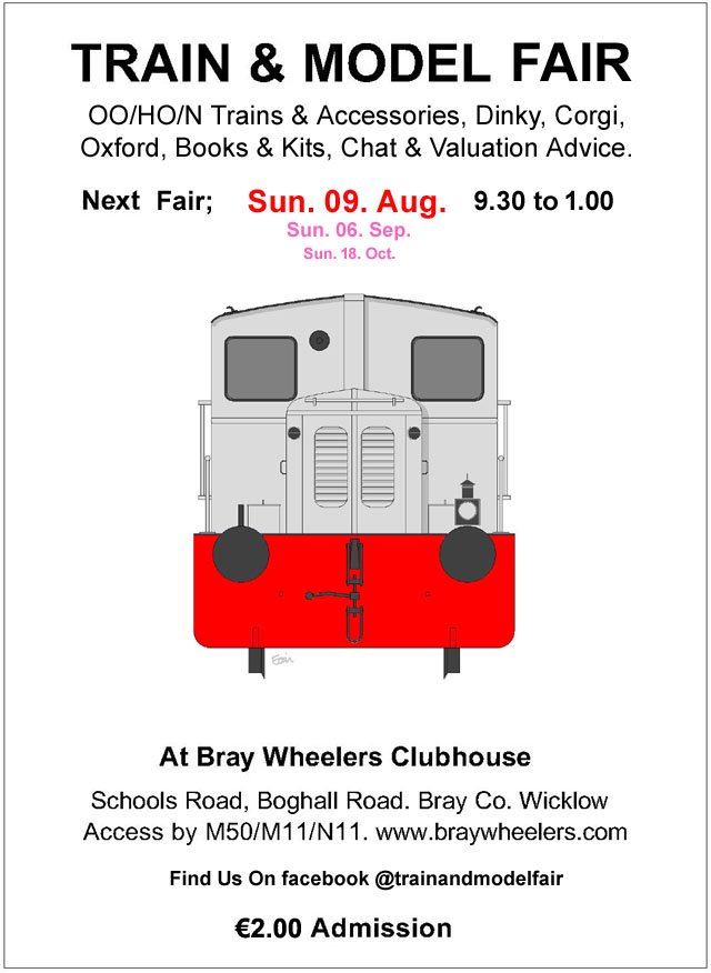
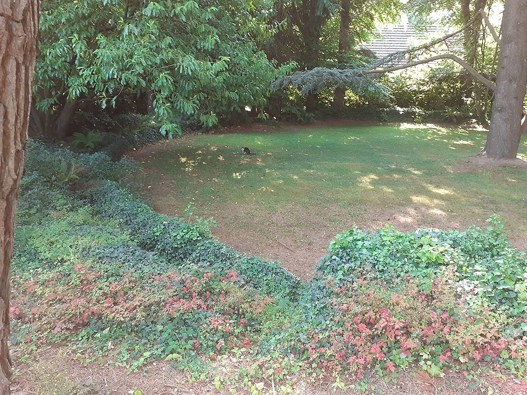
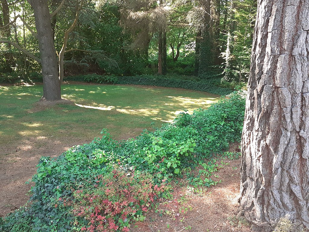
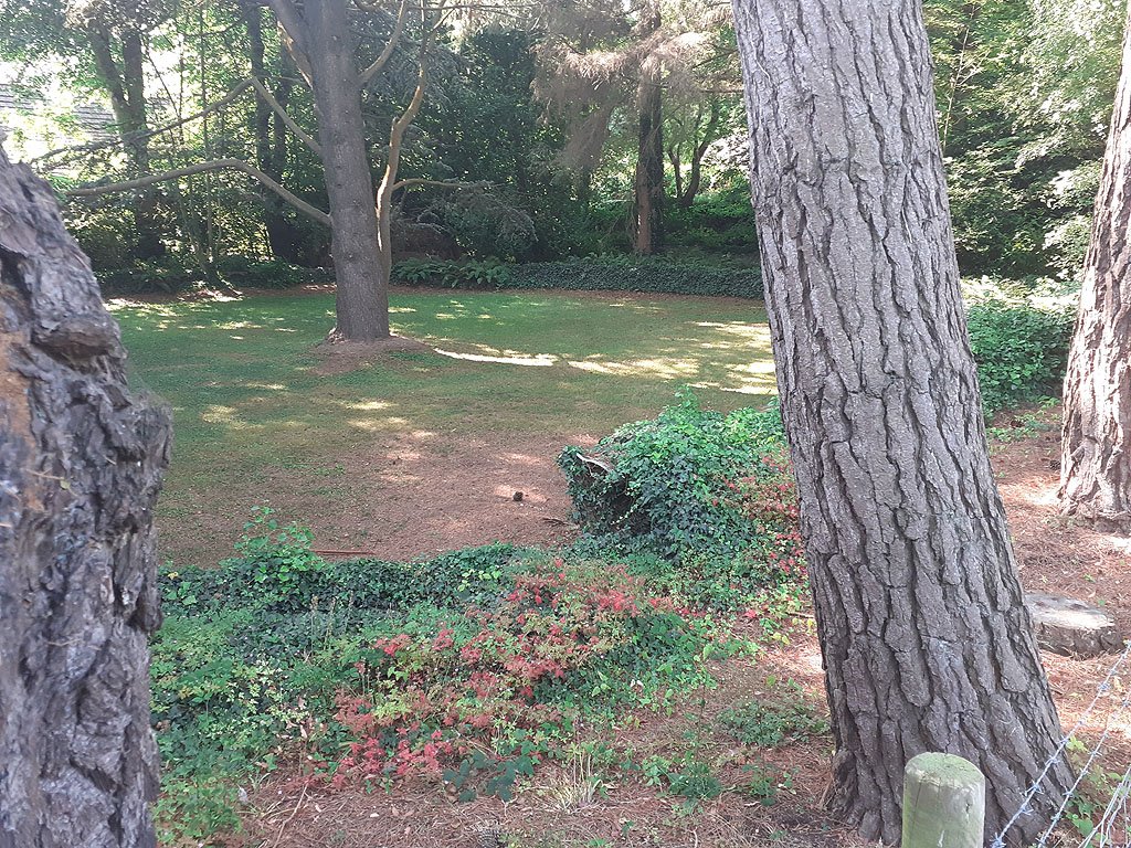
I cant locate the photos I took way back, they are in the backups somewhere! Its a pity because I removed a section of ivy and took photos of the track makeup and the damage! I took these photos this morning from the boundary;- The cat was waiting for the trains. This is a shot of the tunnel entrance, its flattened down now with overgrowth but back in his days Mr Wilkinson stabled his train in it. When running the train one had to duck when going through....... Eoin.
-
The track still exists but is in very poor condition. Mr Wilkinson moved to the UK many years ago to live with one of his children due to health reasons. He donated two of his 3.5'' live steam locos to the local Historical Society, these models are sometimes shown at the Kilmacanogue Horse Show. The track was vandalized with some of the rails being pulled out of its fixings for about a 6 meter section, also a tree branch fell in a storm and smashed two of the concrete arches. It now sits completely encased in ivy which will eventually destroy it. I know the present owners of the property and I had discussions on restoring the track to running condition a few years ago. Our discussions went nowhere as the conditions they set were not acceptable to me. The historical society has organized tea afternoons at the property with the two locos sitting on a section of the track. The locos are in a non running state and the cost of getting them running is prohibitive for the society. I do have some photos of the track in it's current state and if I can locate them I'll post them up. Very sad..... Eoin.
-
https://ckprints.ie/product/station-signs-4-pack-choose-between-small-medium-or-large
-
Very sad, he visited the Train & Model Fair last month, I had a quick chat with him and he was in good form...... RIP
-
until
-
The July Fair Date;-
-
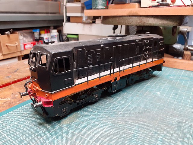
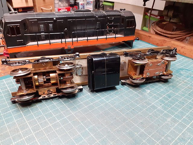
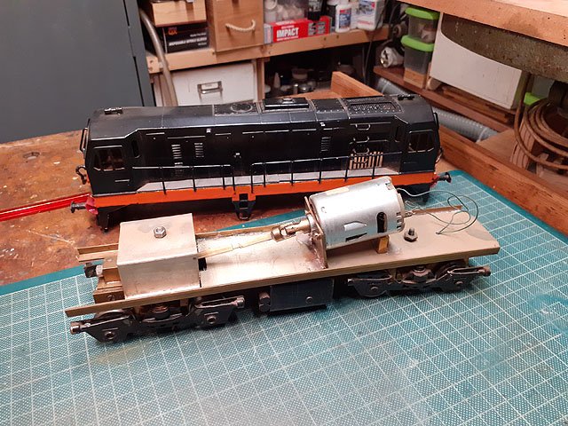
These are built by George O'Rourke (MRSI), the 'Master' Brendan Kelly (MRSI) produced a limited number of kit parts for these locos, and many others, for members to put together. I have a set of parts for the 121 and when I saw George running his yesterday it inspired me to search the dark recesses of my attic and find the kit! Also;- My 141 by Brendan, yet to be finished and may visit Maam Road soon! Eoin
- 69 replies
-
- 8
-

-

-
- o gauge layout
- irish outline
- (and 2 more)
-
I saw it today, a fantastic layout. Well done Gerry & Jenna for a very enjoyable morning, Thanks. Eoin
- 69 replies
-
- 1
-
-
- o gauge layout
- irish outline
- (and 2 more)
-
until
-
The June Fair Date:-
-
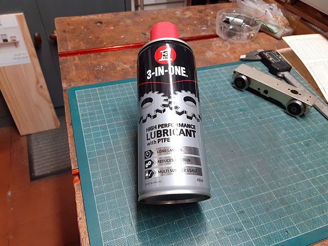
Lightly coating the PF film with PTFE lube every time you fill the tray to print prolongs it's life and makes for easier cleaning! Eoin
-
until
-
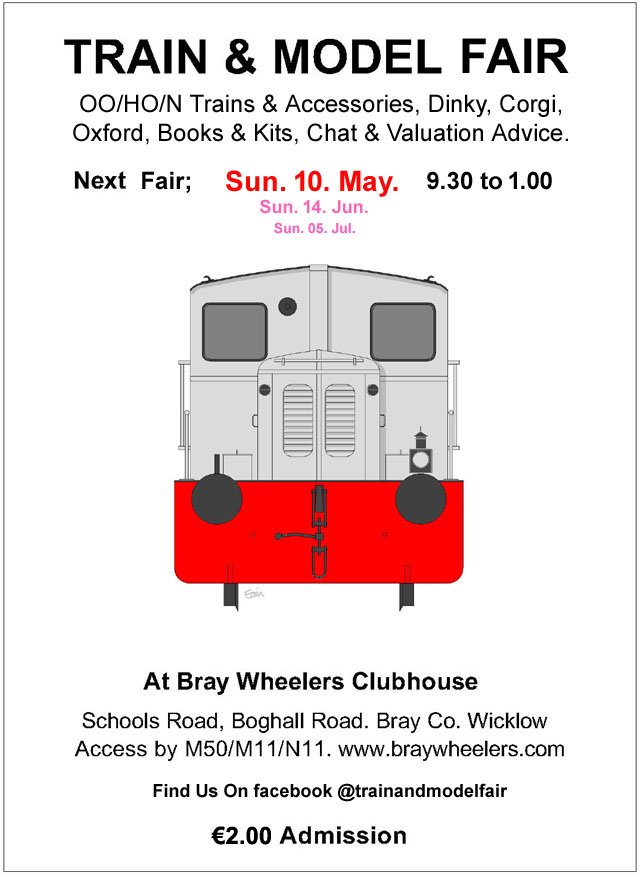
May's Fair Date;-
-

"Voiding the Warranty" - Mol's experiments in 21mm gauge
murrayec replied to Mol_PMB's topic in Irish Models
I use a set of slightly undersized axles in the wheel area while constructing a chassis and then install the proper axles on the final build. Eoin -
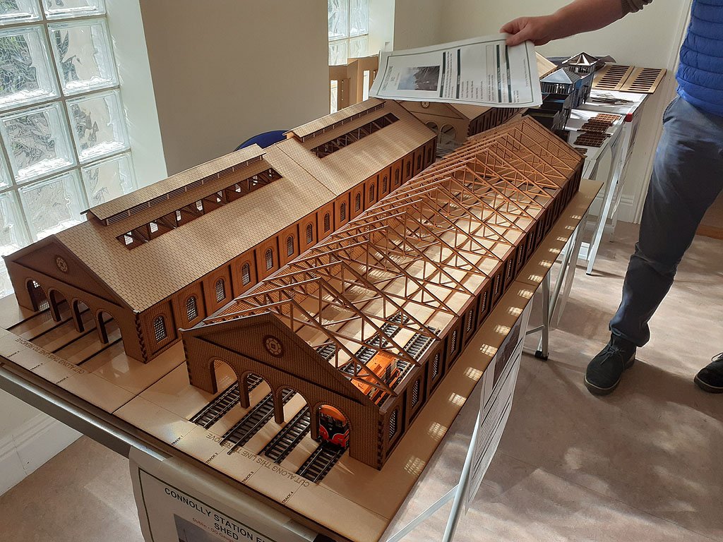
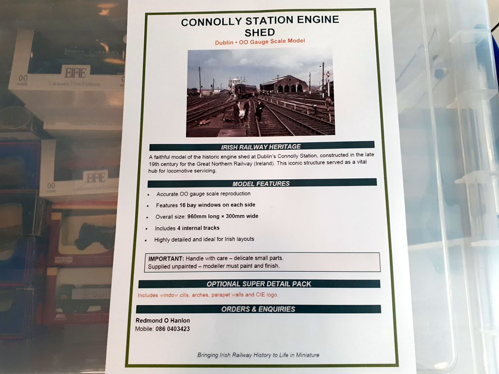
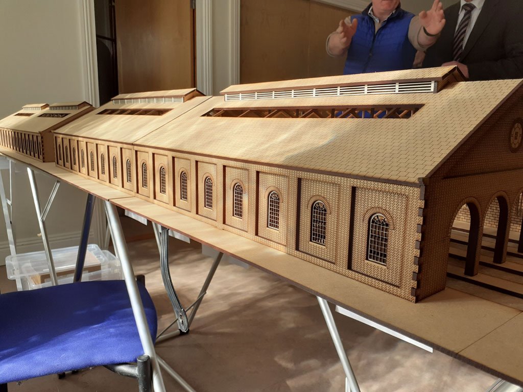
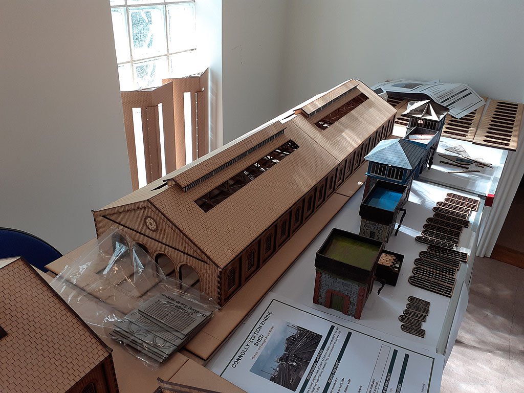
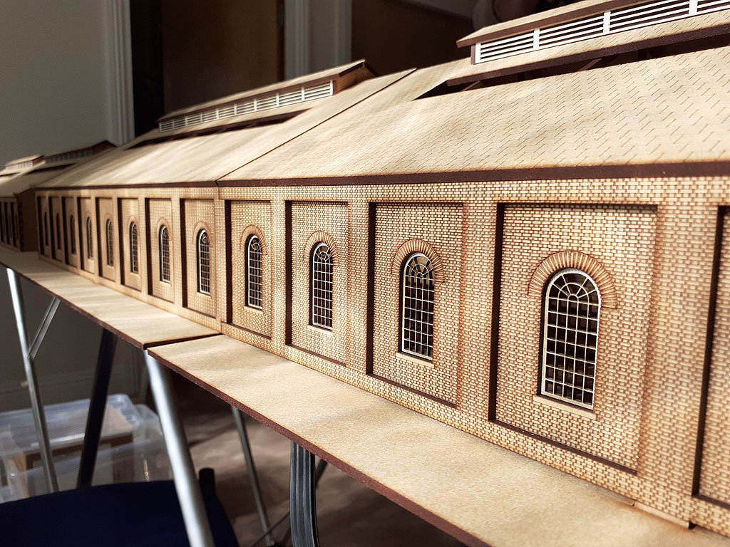
Redmond had 3 Connolly Sheds on display at the Fair, fantastic models.....
- 1 reply
-
- 12
-

-
-
"Voiding the Warranty" - Mol's experiments in 21mm gauge
murrayec replied to Mol_PMB's topic in Irish Models
Here is my jig for extending axles and lining up the squares! A tool maker V block, engineer square and a tool clamp. Most V blocks have a trough at the base of the V, the trough in the block in the background is too wide, the tool maker V block is just right. The setup to square the ends for a flush sleeve. And the setup for the outside sleeve. Eoin.
-
until
-
The April Fair Date;-
-
Tullygrainey is correct, you cannot give up, persevering is the only way.......... A tip for brass kits that went a bit wonky;- Take a blowtorch to the model, heat the whole thing up to melt the solder, hold the melt (don't overdo the heat, just enough to keep the solder liquid) and then pick out the parts with a tweezers, clean up the parts with the torch brushing the solder off with a fiber brush and your ready to go again! White metal parts, if any, need to be removed first with a soldering iron. Eoin