-
Posts
3,490 -
Joined
-
Last visited
-
Days Won
11
Content Type
Profiles
Forums
Events
Gallery
Blogs
Store
Community Map
Everything posted by Glenderg
-
The UK rail press have been on about this for years in their editorials, the fear that a PlayStation will nuke the hobby. It's unlikely to ever happen as railway modelling, and not the armchair variety, is dynamic and physical. It provides a good skillset of how to overcome engineering challenges, electronics, artistic methods, history, photography, research and so on. If I had my way, railway modelling would be a compulsory topic in secondary school. That said, you'd have add a module on personal hygiene
-
You lit the fire, I fanned it, you're a retired moderator now. Sleep tight.
-
Many who've replied on this thread do not remember the last time anyone had a serious opinion about IFM stock, which was me, and it resulted in IFM leaving here as a contributor, several bans being handed out, and some pretty wild personal insults to me, which will be settled in a car park eventually. (it wasn't IFM incidentally) I have no particular issue with customers who want to buy his stock. Much of it is as good as MIR was back a few years ago, and those kits are still selling for a fortune on ebay, but for any serious modeller, nay rivet counter its not up to scratch. In order to bring it up to craven standard, there is a hell of a lot of work to do, if you can accept compromises like parts of the under frame and sole bar being removed to accommodate a bogie. But that's me. I'm a nerd for this stuff and it gets my goat. I stay silent because he satisfies an audience here. But many on this forum just want to play trains and have rakes of stuff that satisfy their era. The two foot rule applies - if it looks good to, you buy it. Tommy brady is actually filling a hole badly needed in this small community - to provide rtr examples of commercially unviable models. To that end, I'd like to apologise to IFM for any offence I may have caused years ago. What I do take issue with is people fantasizing about 5 pole motored, working fanned A classes, and superior detailed 121 models that would surpass the current Murphy Model stock, and then posting poor photos and "whoop!" Reviews without mentioning any potential shortcomings. If you're going to take photos, take decent Res ones, in decent light and let the punter make his own mind up. 90% of this forum is comprised of lurkers, and they take a lot of the posters words at face value. Nobody wants to purchase an IFM model in the mistaken belief it's to the same standard as a MM craven. Be fair! The man has a market for his stock, and I'm not going to bash it, him, or his stock. He's shown an eagerness to improve by virtue of his stock offerings. So. Let's not turn this into another bunfight gents. Horses for courses, live and let live. It is toy trains after all. Rich.
-
Seriously worried about your manliness scale, David. It may be a bit more viking than it appears!
-
Must investigate Postiche. Must bookmark this page. Thanking you sir.
-
Same as above.
-
Reserved for Further Updates
-
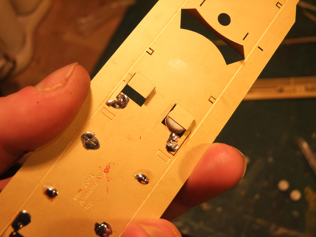
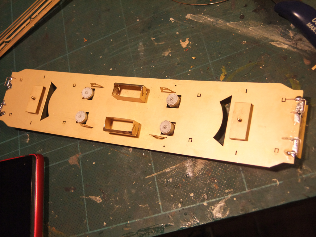
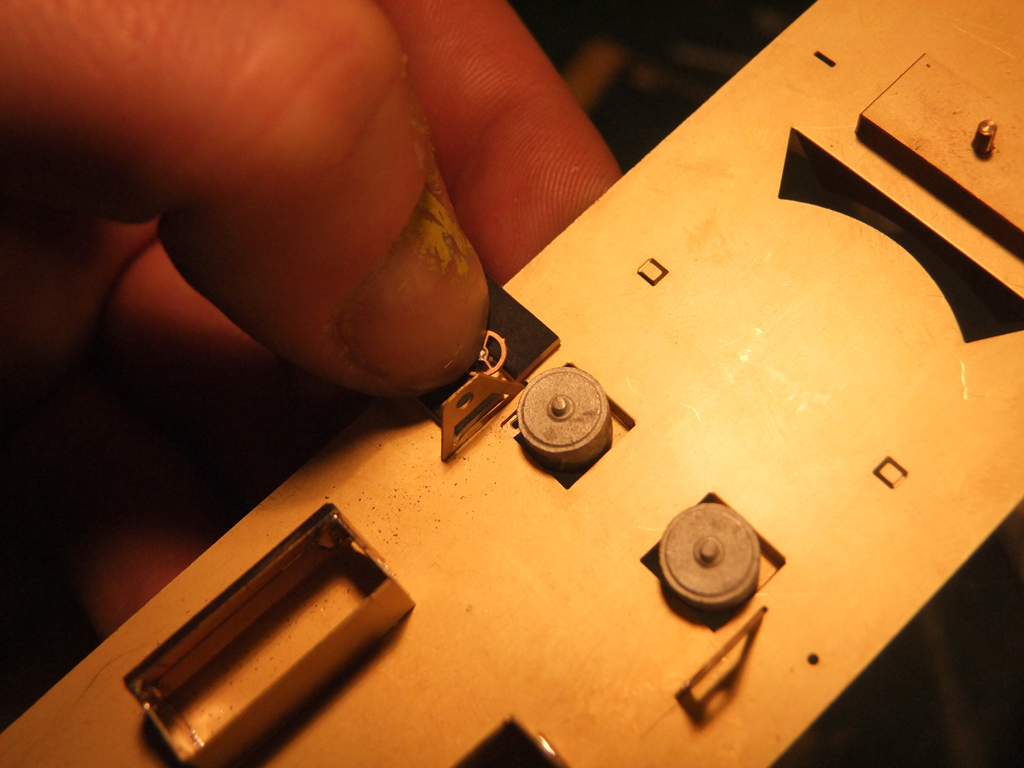
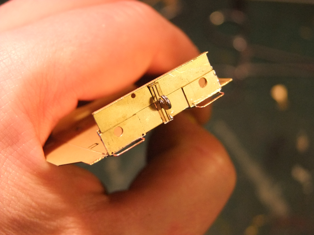
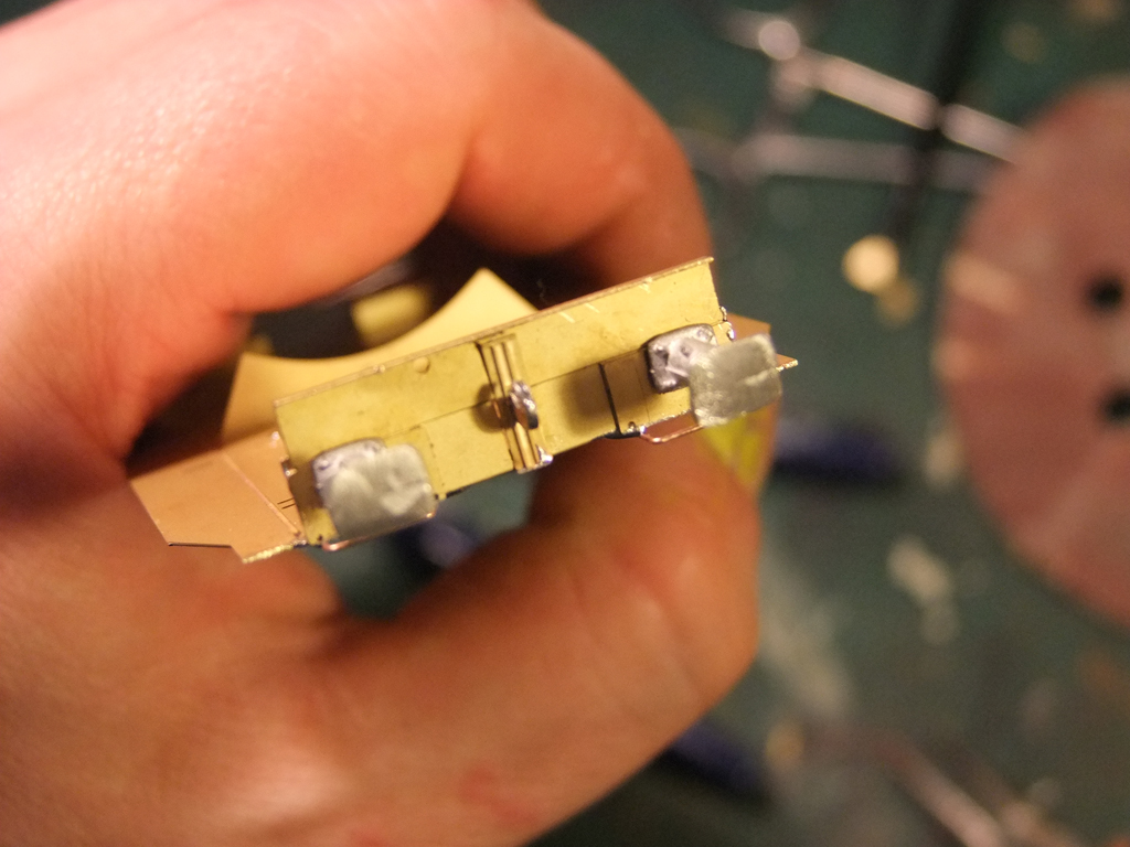
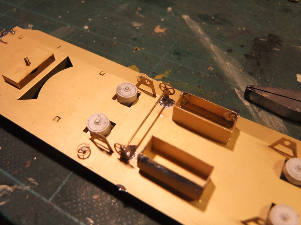
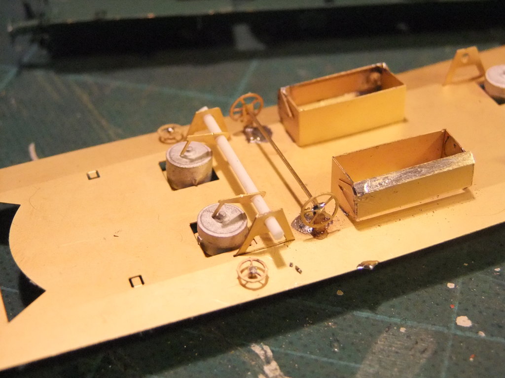
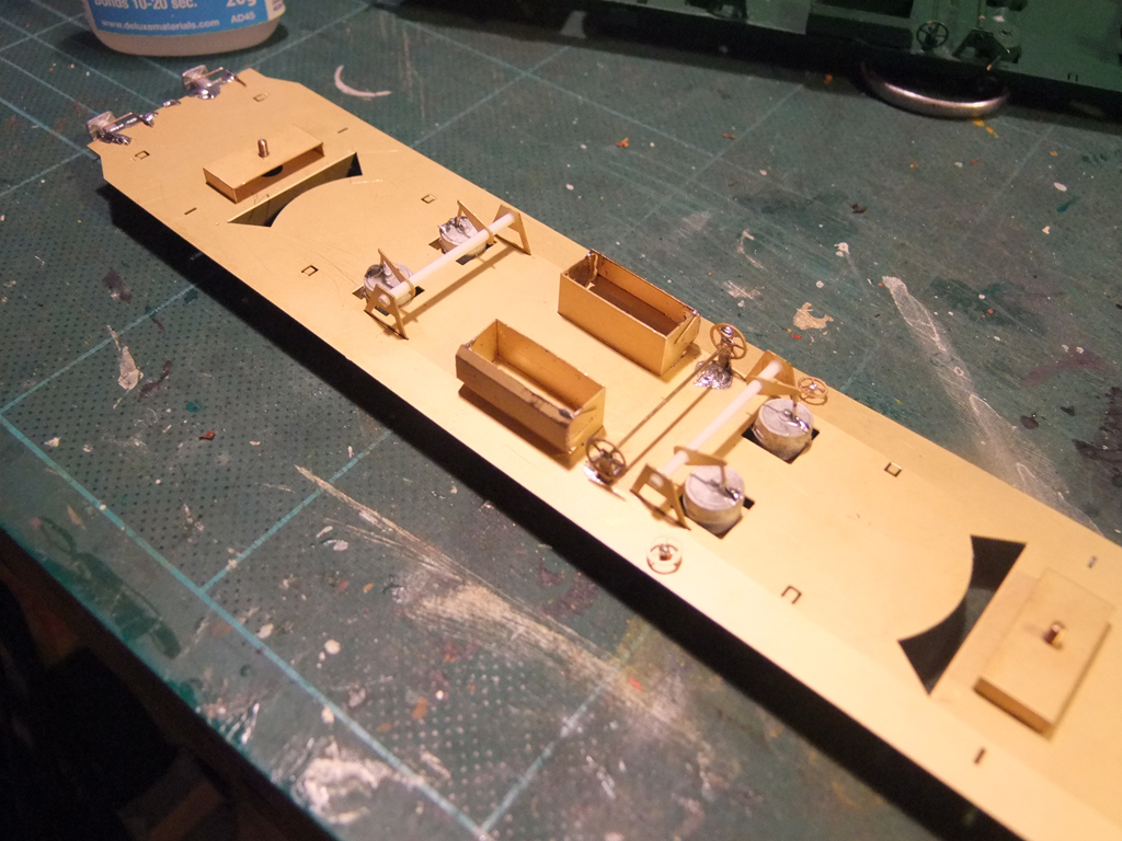
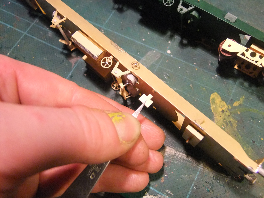
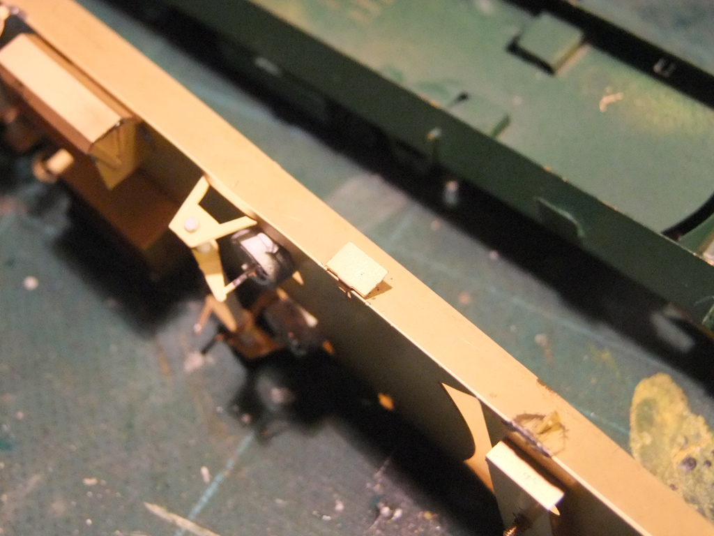
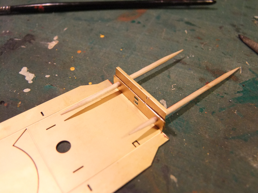
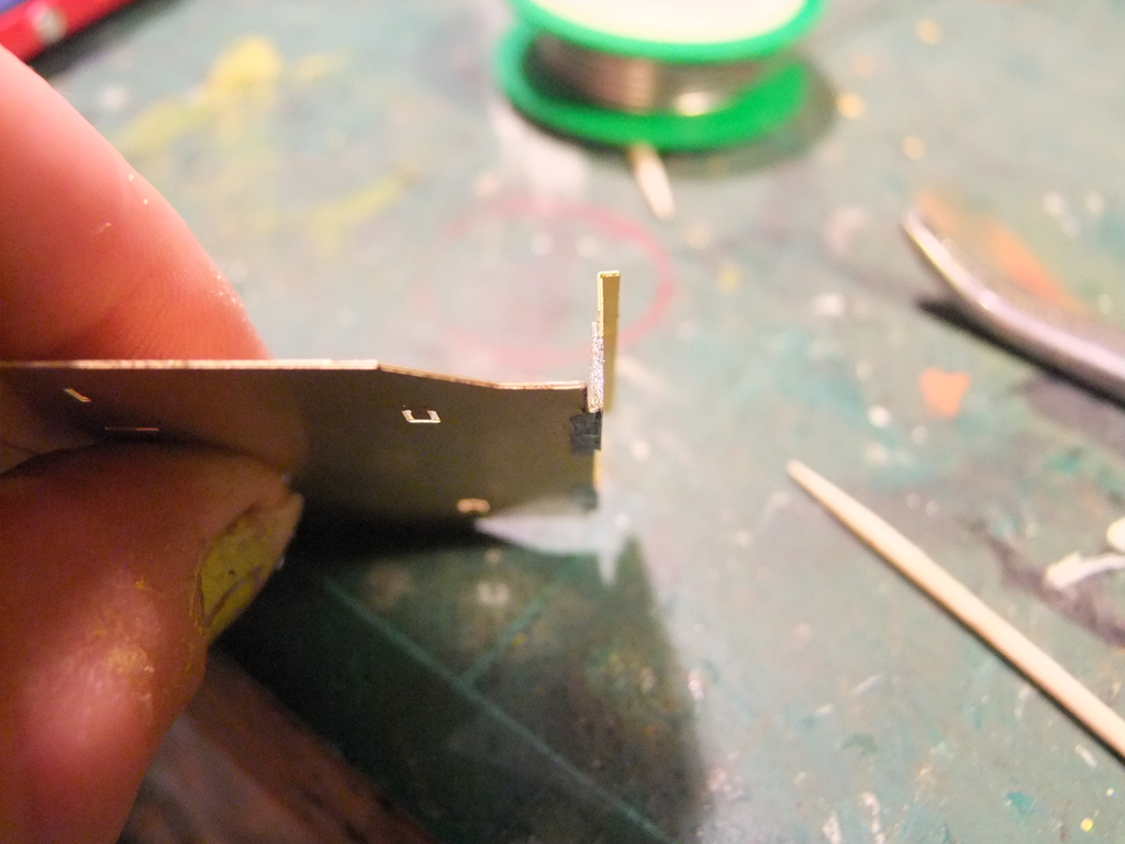
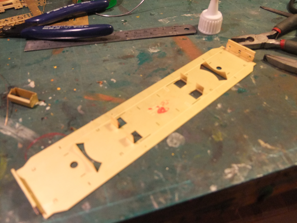
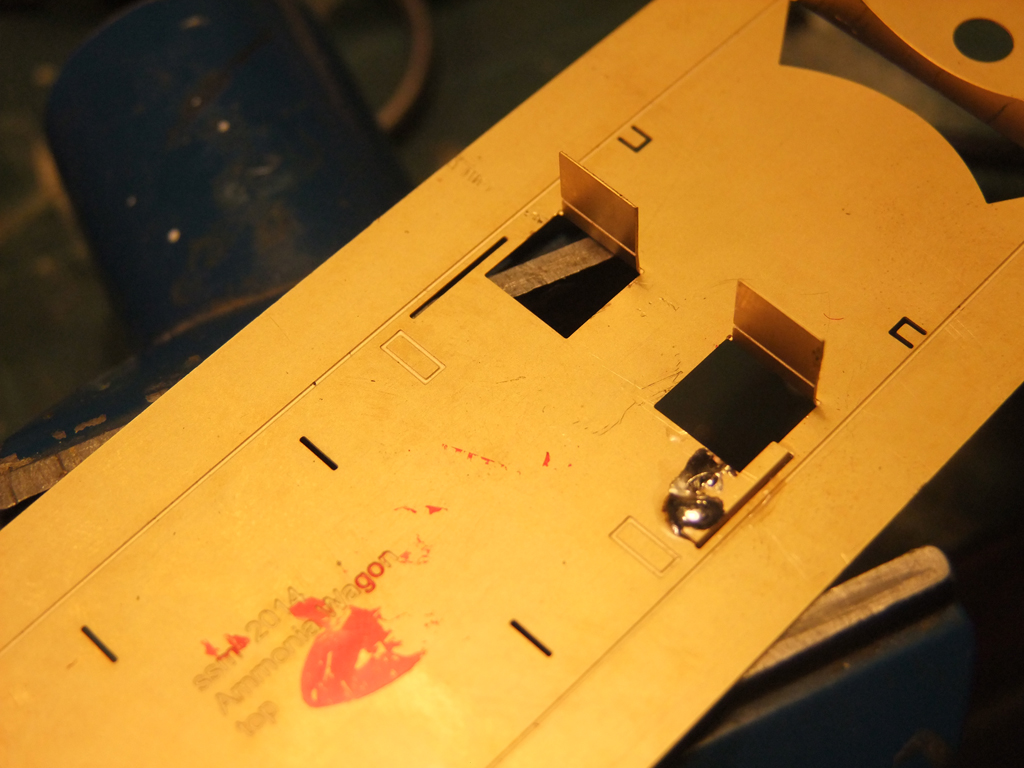
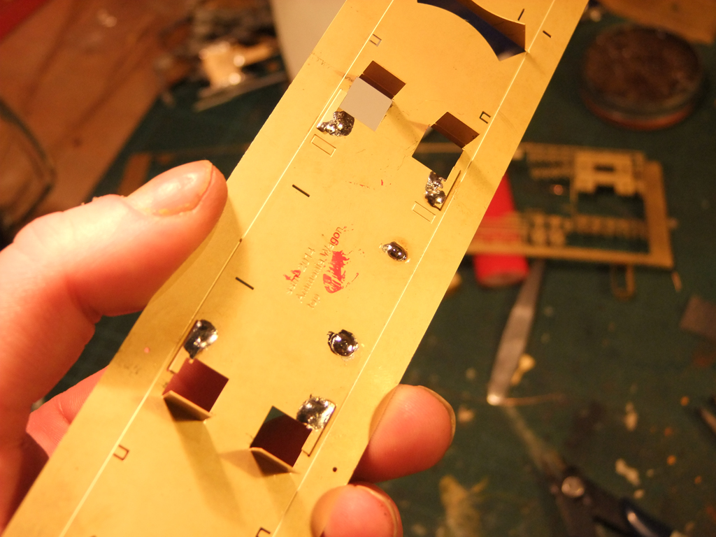
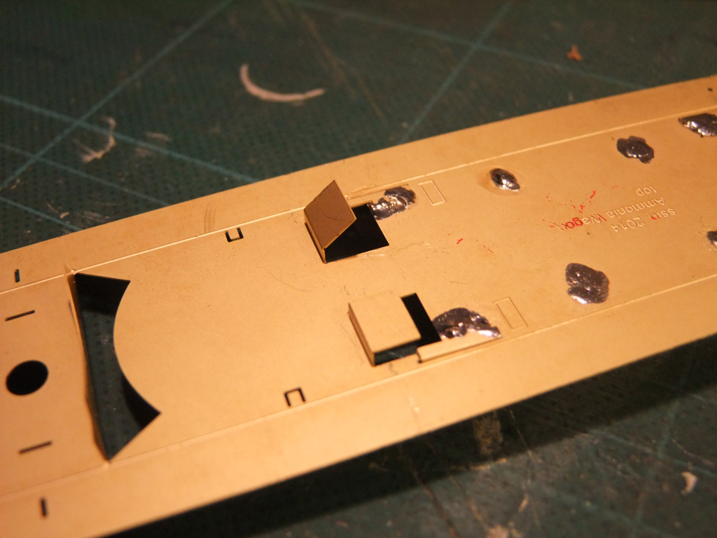
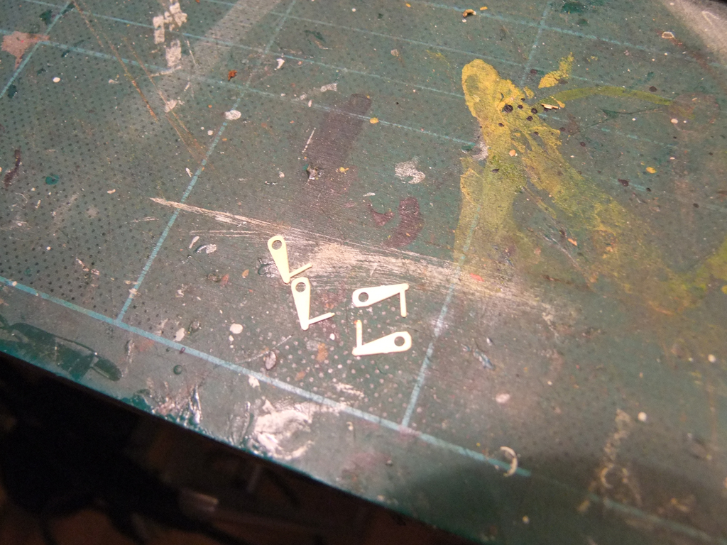
Flux the brass plate and the whitemetal, and using the fairy wand approach zap that sucker. Or four. resulting in this.... Now I don't have a photo of the bogie support cradle, but fold it up, drop and solder a bolt into the centre pointing away from the tabs. You can see the two of them here after being inserted with the small bolt thread to go into the bogie. Get a small bit of card and cut a notch out of it, about 1.5mm thick and place it over the wheel hole on the solebar as such. Long finger and thumbnails don't conduct as much heat as bare skin, so hold the wheel in place while you solder from the rear. Once done, remove as much excess bar as possible, otherwise it will make a mess of folding up the solebars. To tidy off the bufferbeam assembly. Locate the coupling bar cover and place it like so. A thin rib of solder at the bottom should do it. Pop in your fat coupling hook and solder from the rear Now put the buffers on. Align them as closely as possible and apply heat to the rear. Bend the solebars ever so slightly to expose where the etch is on the opposite side. There are two small brackets that fold up and need to be placed about 2mm in from the fold, half way between the boxes and the cylinders. Insert the larger wheel and tube, add the outer wheel, solder as before and trim off the excess. I lost the brass tubes that came with the kit, so I used a piece of 1.6mm styrene rod, and put the cylinder levers onto it like below. How that blob of solder got on the solebar, I've no idea. I secured the rods with superglue to the supports and got the levers in approximately the right position. A drizzle of solder connects the levers to the cylinders. There are identification plates to go on to the solebar. They can be soldered on, actually they have to. They will fall off if glued on, guaranteed. Don't worry too much as they won't really be seen when cylinder is added. But if the weld looks like a teenagers face, file it down a bit before you fold it up. More to come later in the week.... Richie.
-
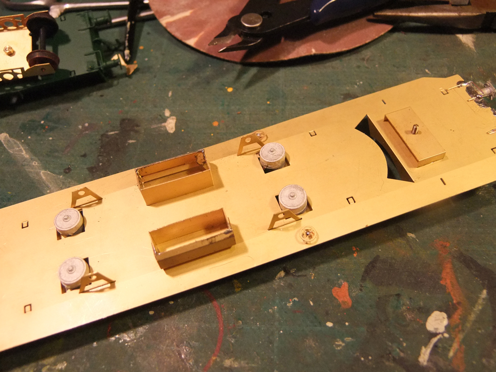
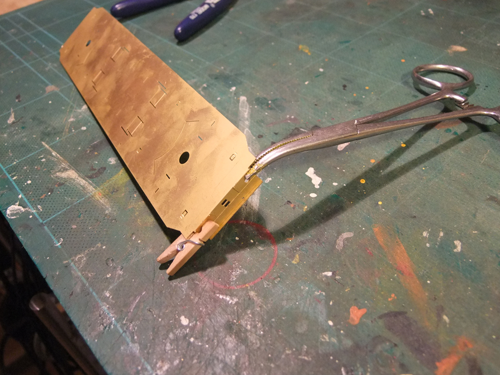
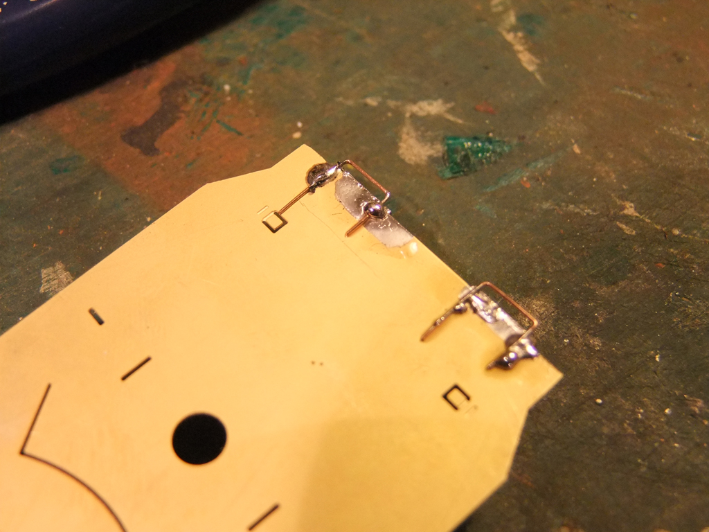
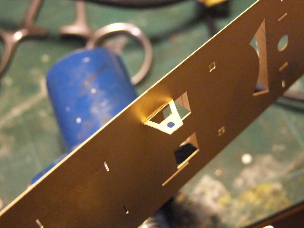
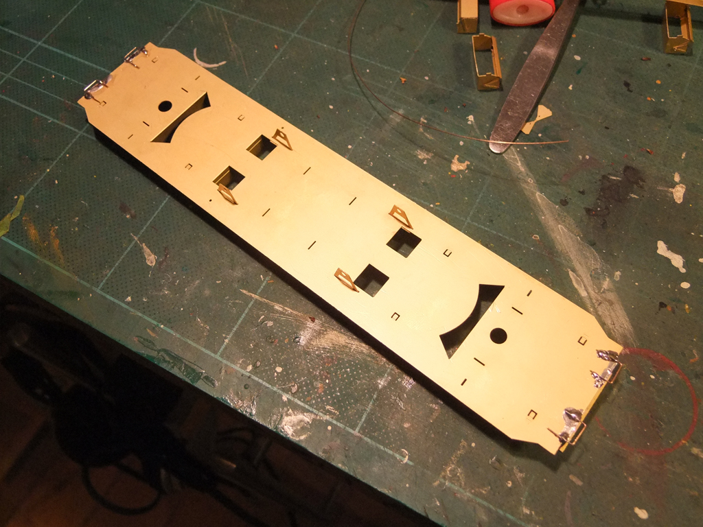
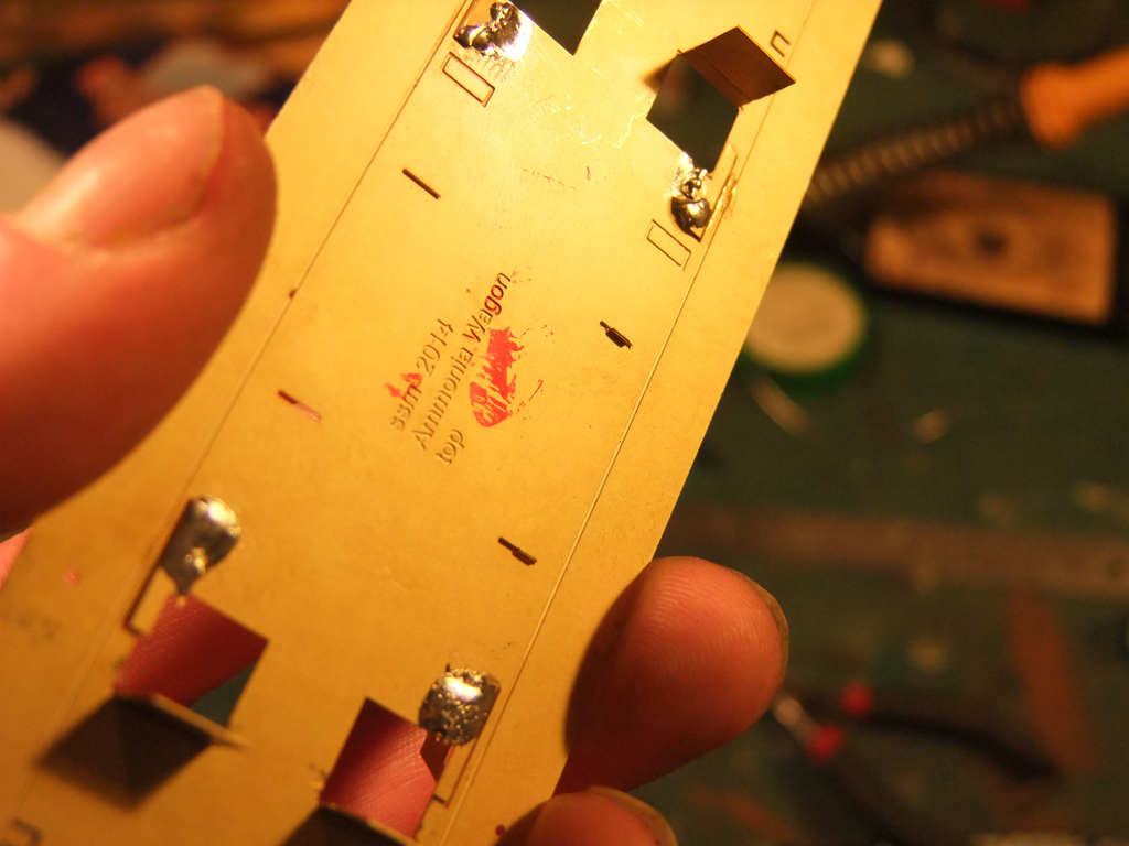
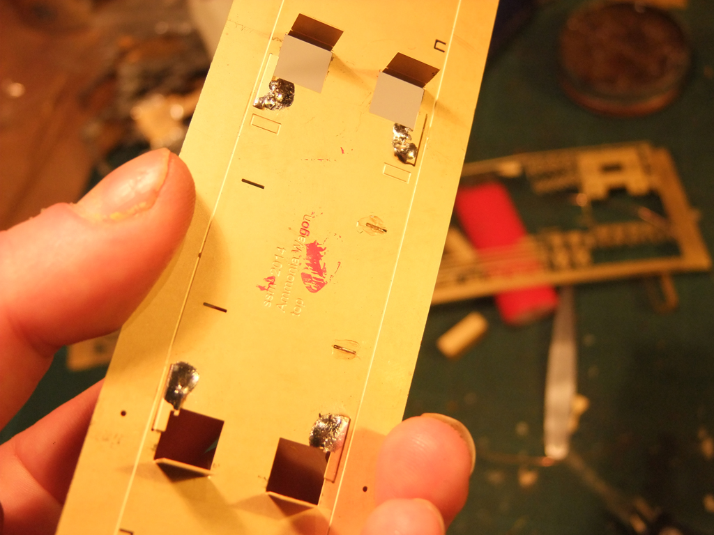
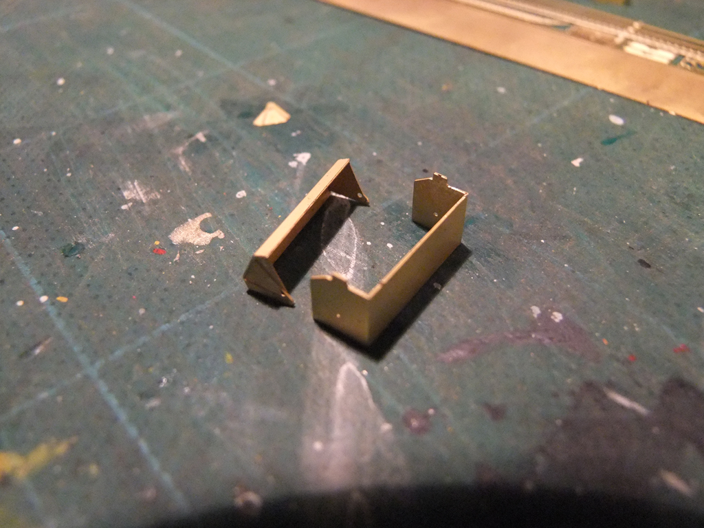
There are two options for aligning the holes in the buffer beam. One is a straightforward clamp or A light coat of flux on the underside where the two brass plates meet and run the tip of the soldering iron across it. You also see how the filing back of the red parts ^ will help keep the bufferbeam square. There are holes beneath the buffer opening for a sort of handle/step type thing. There are no corresponding holes behind it and I broke a bit trying to drill it so you can just glue or solder some bent wire underneath. Might try staples later, already folded after all..... using a ruler fold up the tank cradles. Do the same with the cylinder support plates (4) Take care as these are double etched. You should now have something that looks like this. (Clean your glasses...) DON'T FOLD UP THE SIDES YET - DON'T EVEN BE REMOTELY TEMPTED!!! Insert the brackets you made earlier being sure that the correct pairs are used, and solder away from the solebar etch as shown. She should look like this now. Now for the boxes that are slung underneath, insert the tabs into the slots and pull them toward the outside of the wagon. Shear off the protruding brass (this cuts down on the amount of solder, heat and messing) and add a lick of flux. Load the tip with solder and just like a fairy's wand zapping a frog into human form, do similar to the joint with the soldering iron. Next, fold the four upright plates like shown. These shelves will be the support trays for the vacuum cylinders. PART III Shortly
-
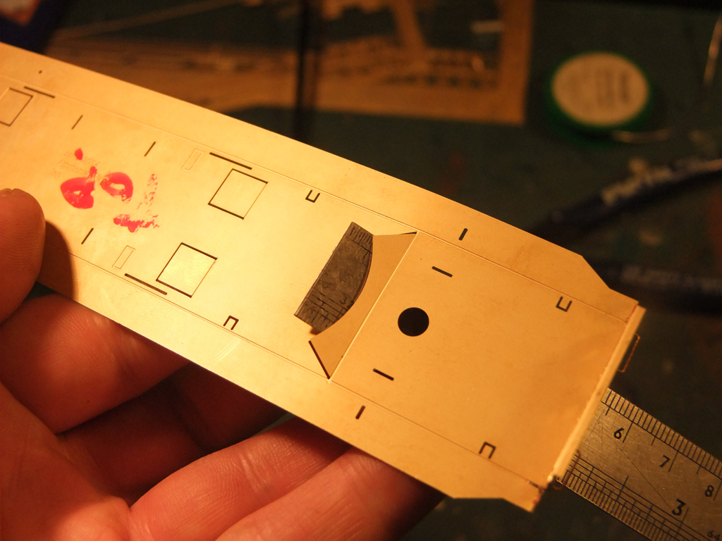
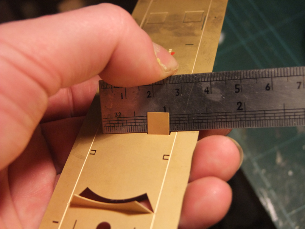
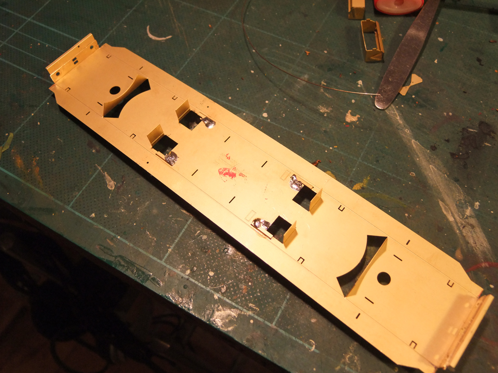
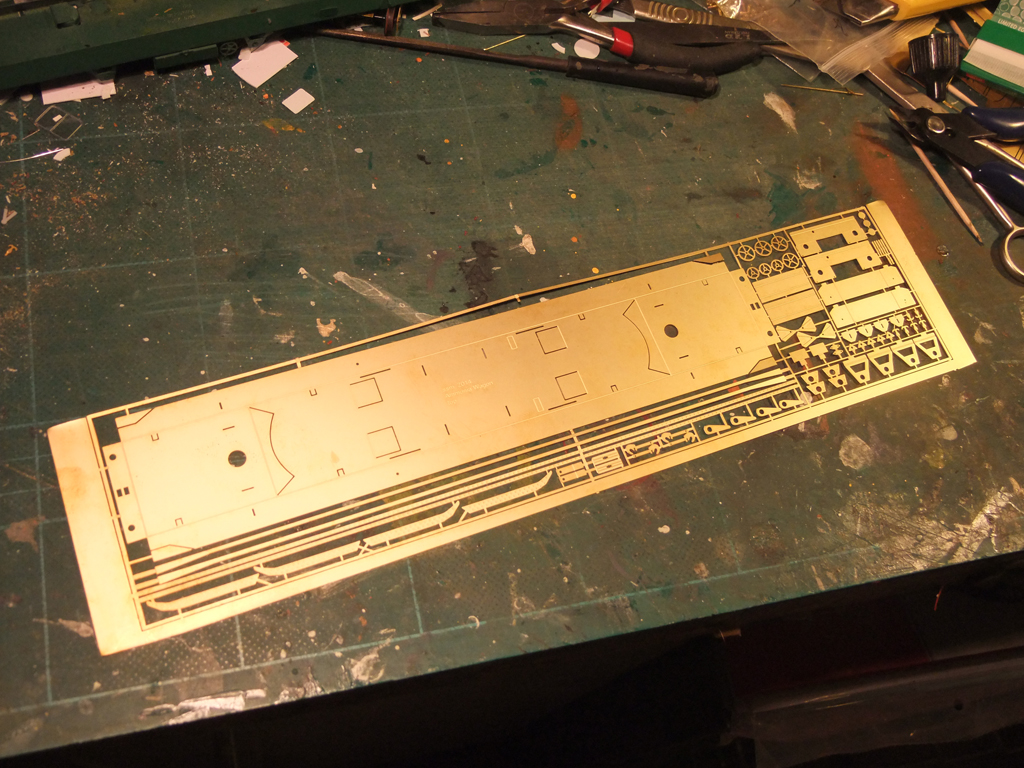
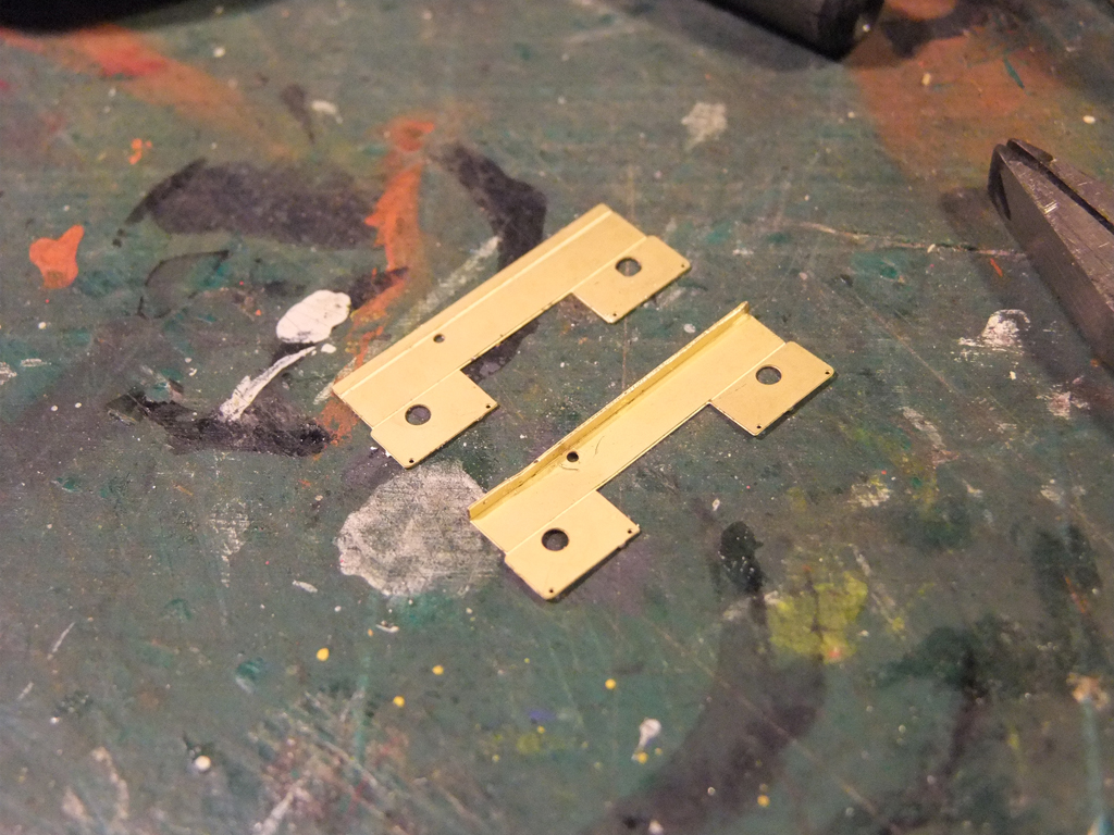
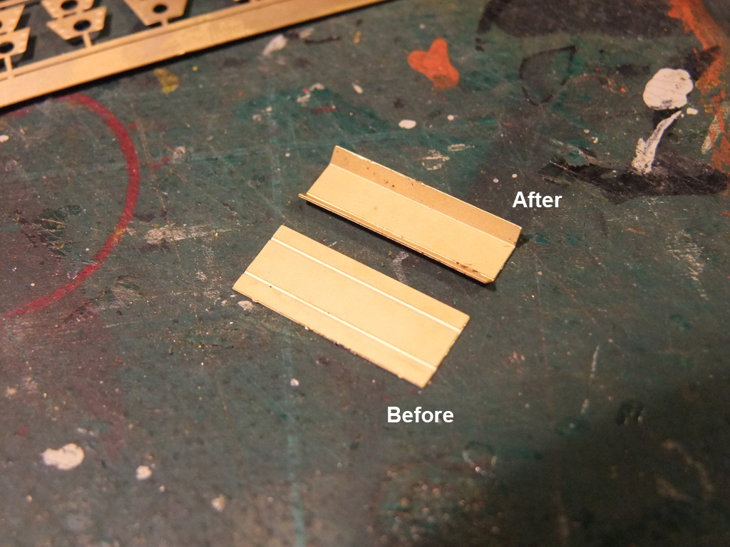
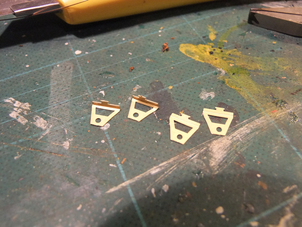
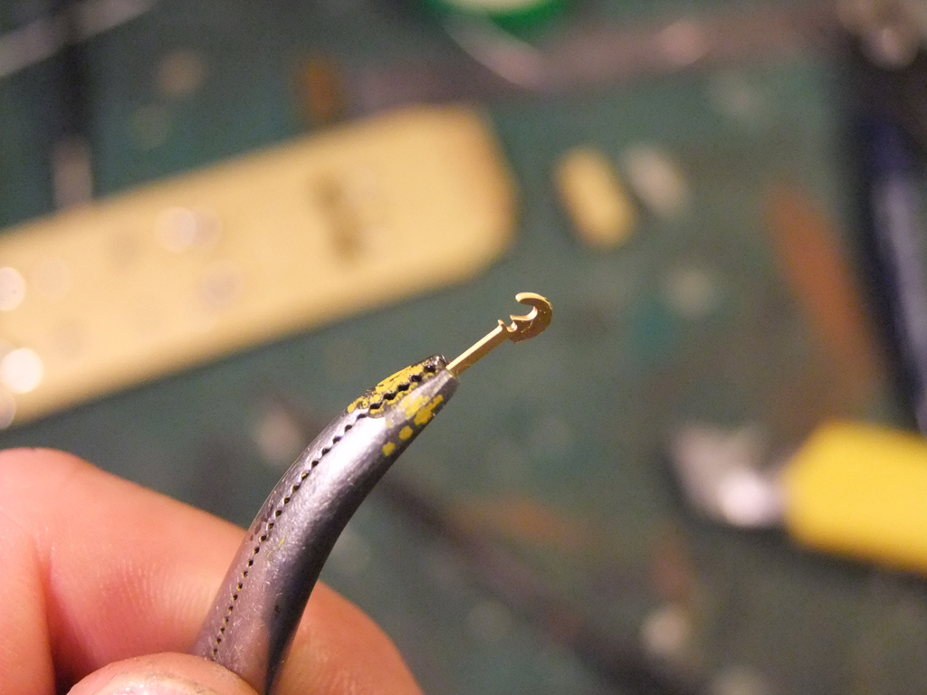
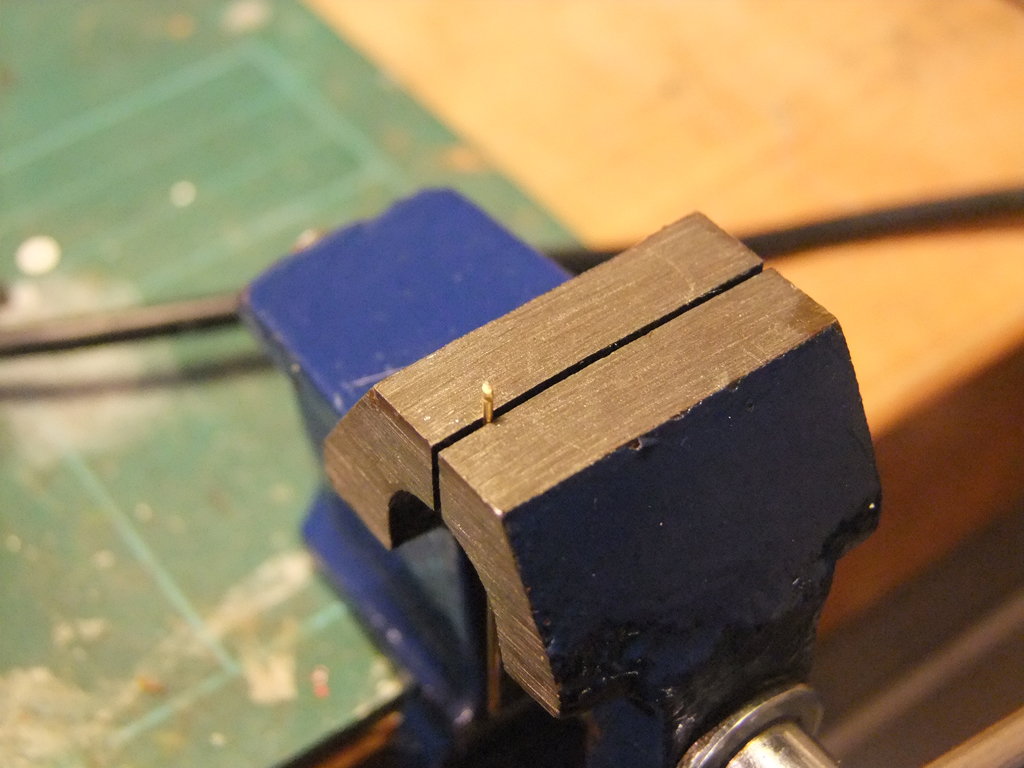
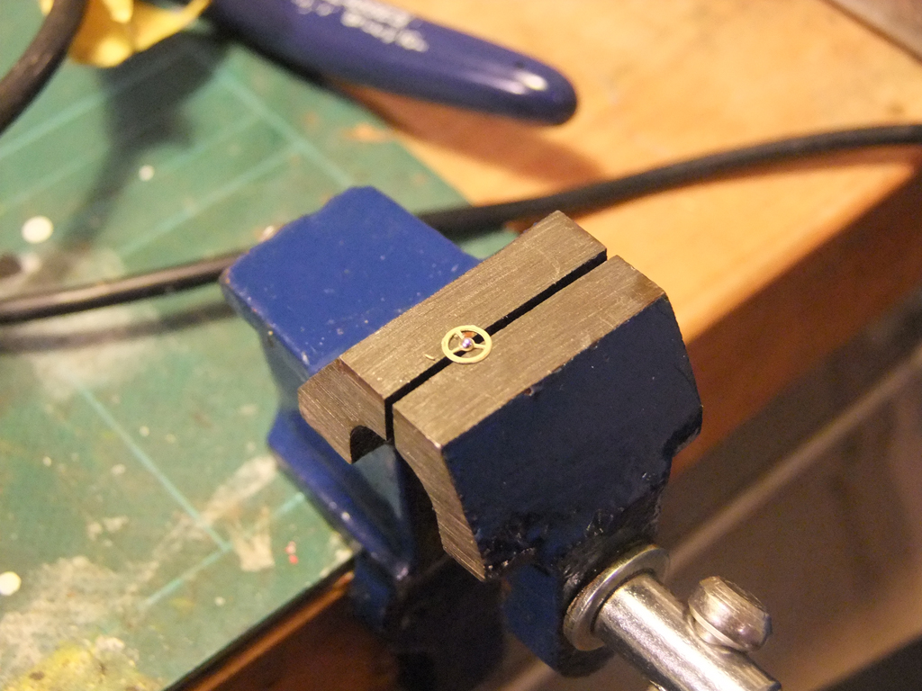
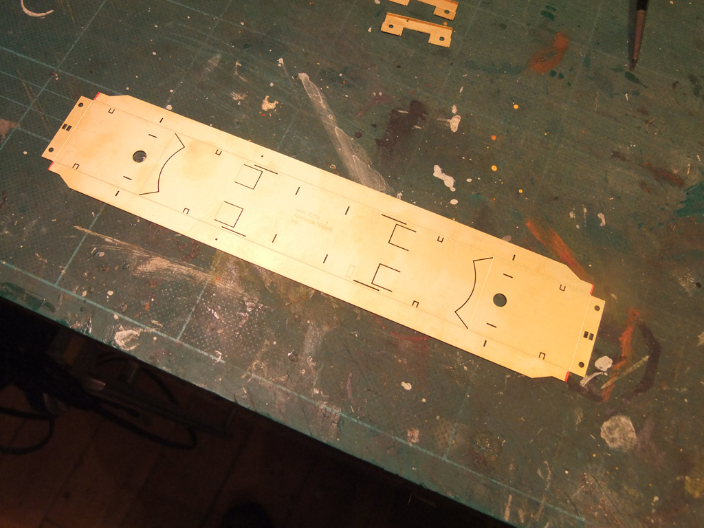
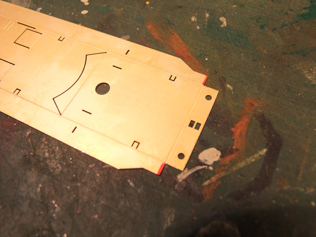
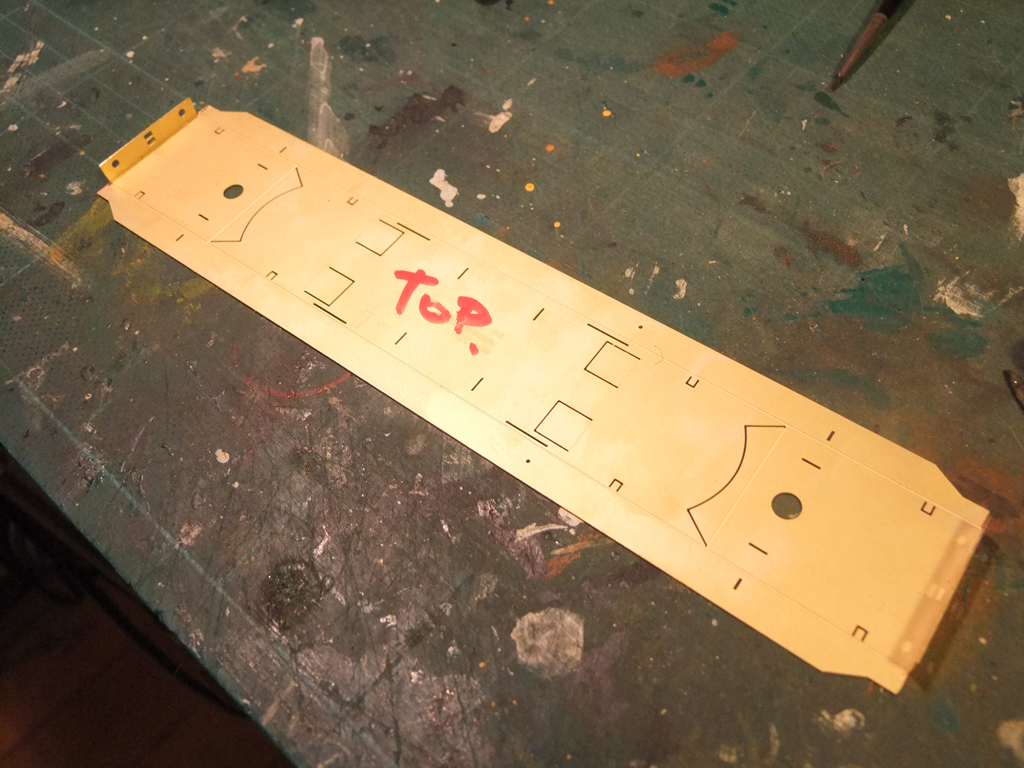
I'm told there are boxes of these lying on shelves the length and breadth of workbenches, so no better time to do this. I built one of six a few months ago, all glued, and promptly lost the instructions, so to build the remaining 5 I did it based on experience. I've done a few things assways as I went along, but I think this is the most straightforward method. Also, I'm a brass novice, but I found that none of the scary items like resistance soldering gear and complex jigs are required for the job. A standard issue soldering iron, plumbers flux, and a roll of solder do perfectly fine, and I'd encourage anyone eager to try brass kits to give it a go on this one, as many of the joints and welds will be hidden under the tank. Only you'll know they are there Superglue can be used on this kit also, same process as below. And for folding things, always fold into the etch side. First things first, a clean bench, some choons on, and a drop of Modeller's Elbow. Oh and the main etch for the kit of course. Like airfix kits that get you to make up the awkward stuff first, and then do the easy bits, that's how this should be approached. Remove the buffer beam pieces (2) and fold up the top flange only. The lower etch is decorative only. Next remove the components for the battery box housing. The outer doors have to be folded 45 degrees like so . There are 2 webbed pieces that fit into that outer door, and the main box folds up like so. The enclosure is the same size as the completed door cover, so a bit of tweaking is required to get the door cover to fit over and align with the holes. (There are 6 different versions of this box on the wagons I'm doing, a wee bit confusing!) Remove the release wheel supports. Note that they are handed right and left to match on either side of the wagon, and bend up the top piece. There are four coupling hooks. Remove and just tidy up the hook end, don't worry about extras at the rear. Pro-tip here My brother in-law is a cattle farmer who gave me a present of this veterinary clamp, a vet left after her. I'd recommend getting one, preferrably a new one via an online shop Anyway, clamp two of the hooks together, give it a light coating of flux... and with a small bit of solder on the tip of the iron, just run it over the surface. Repeat with the other two hooks. The buffers next - take the four out and either by rubbing on a bit of wet and dry sandpaper or a file, remove the seam lines on the outside of the plate and any large lumps or bumps. Check by passing them through the bufferbeam for a not too tight, not too loose fit. Remove the vacuum release levers and trim off the excess. There are two little solebar wheels and four larger release wheels needed. Find the appropriate brass rod and do like this. Clip off the excess..and a tiny bit of flux on the centre. Hold the wheel in place with a tweezers also, otherwise the solder on the tip will suck it up. Turn the rod around and repeat. Then cut in half for the smaller wheels. For the larger ones, only attach one wheel until it's fitted to the wagon. Remove the main panel from the etch, and using a file, file back the areas shown in red by about 0.5mm. This is so that the solebars don't foul the buffer beam which would result in the buffers pointing down at the track. Now, let's get it looking like a wagon now Make sure you have it the right way up - the piece with the SSM copyright text should be facing up, and bend up the bufferbeams. Part II Shortly.
-

image links being lost on irishrailwaysnews.yuku
Glenderg replied to Junctionmad's topic in General Chat
That's why I host with dediserve, a reliable partner in the cloud! The reason I have a 35gig library of photos is because no matter the topic, era, or location I'll download it, and put in a folder. If I can't download it direct, I'll screencap it, with author and copyright data so if someone needs a link it can be Googled handy enough. It's for my educational use only, and I give dues when necessary - the wanderer and Mr. Marshall in particular. Many of the photos are screencaps from fotopic and I wouldn't dream of abusing the authors rights by reposting them here, or on FB. But if people need specific photos, just ask. Someone might have one and email it privately, so long as it's kept private. Remember, you'll never know when you might need that shot of a tablet catcher on the side of an A class. -

image links being lost on irishrailwaysnews.yuku
Glenderg replied to Junctionmad's topic in General Chat
Is this the page? http://irnirishrailwaynews.yuku.com/topic/2270/The-good-ol-days#.VjkCdrfhBpg All the images are working for me... -
See the attached Kirley - Mainline Park Royal.pdf Vent Locations and Roof Strapping indicated.
-
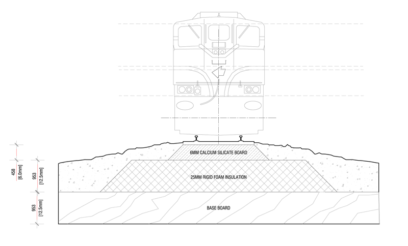
Just to add a practical note here lads. If you take all the precautions of layering and putting a substrate between the board and the track, then fill it with liquid glue, the whole thing becomes a solid object and will happily conduct noise. You could get a 6mm calcium silicate based board for the track bed, with a rigid insulation foam underneath (min 25mm) extending at least 25mm either side of the outside of the sleepers. Provided you kept the ballast depth to no more than 5mm in any one spot, and glued it the traditional way, you would have almost zero acoustic conductivity, I reckon.
-

SDMRC Exhibition - Blackrock Collage October 24th-26th.
Glenderg replied to steventrain's topic in What's On?
Ed, when you go to a banger rally, or a car boot sale, there's always a burger an coffee yoke there in the car park, fellas sitting around chatting about what they bought. Be reasonable, nobody's asking for silver service, I missed the carvery for exhibitors and near starved. There's bound to be a middle ground on this? Anyway, one of the great things to come out of the show was their magazine, and many have it tucked away or thrown in a pile. It's a superb piece of work, and not the navel gazing pomp I thought it could have been. R. -
Well spotted Minister! This is all I can contribute. A Signal Cabin plan as of 1961 OS Map Layout (1946 I think ????) And if you were to do the majority of this in 00 scale/4mm it would need about a 1200mm x 8500 mm board to stick it all on. 00_Gauge_Charleville.pdf Richie.
-
No, the MM locos differ entirely across the range, little or nothing to do with the Man himself. Weathered 181's have a mauve hue, the 201's have a salmon hue, the 086SA is mighty sour brown, and the MK2d's are off the mark completely. Unfortunately there is no MKIII orange, or "supertrain" yardstick for ordinary folk to say - "this is the colour, can I have a tin of this" As noel said in post 2 on this thread, the closest to supertrain/black and tan that I've worked with appears to be Phoenix Precision paint golden brown. It works for all eras, looks right neat and weathered, and ties in with the photos of the era. R.
-
I'll have to dig them out but there are oireachtas transcripts of fervent bacbenchers demanding that CIE, in the midst of the second world war mind, distinguish their new CIE green as distinct from the Maunsell green used across the ditch. It was noted that the British used a healthy amount of blue in their green shade, ala jaguar green, and the irish should opt for something with more yellow,to represent the Applegreen. This was a political motivation rather than one dictated by a graphic designer. I have a massive problem with the contention that the tpo at downpatrick represents any shade that actually ran on irish metal, but that's an argument between me to and JB! Review for yourself the photos on swissirishernies Flickr account from that period, in colour, and making allowances for poor film, bad cameras, show me one colour photo that remotely matches the dirty mint green of the TPO, and I'll hang my hat for good. As for the orange, Patrick Scotts tan colour had nothing to do with his cat. His ceramic paintbrush pot from Spain was that colour. Anyway, that tan colour as we call it, when diluted with about 20% white is mk3 tippex orange, yet another CIE reuse and recycle scheme. Try it with them phoenix paint pots if a non believer. I believe a challenge has been issued.... R.
-
Cheers Noel, they were done a fair bit before Des brought out his kit, which are tidy little numbers in their own right. And they share the same chassis dimensions as the ballast wagon, handily enough.......
-
They "were" my scratchbuilts so.....
-
I'll have a look downstairs later Harry.
-
They're my scratchbuilts, not Weshty's
-
Brian, I have a large paint sample from the tumblehome of a MKIII that I use as a reference. I'll try and get some photos in the daylight with other orange MM181's if someone's after the bang on shade. All I know is that RAL 2011 is not right to represent an in-use MKIII paint. The Crown Trade shop in Baldoyle, Dublin has a scanner that will scan a paint colour you have and replicate it, or at least give you a code. What livery are you doing your A Class in - IR? Richie. Are you going for the IR livery A-Class then or an earlier supertrain shade?
-
The most recent example of this is when they painted the two 141's in the black and tan scheme prior to preservation. The lower quarters are in MKIII ORANGE NOT TAN. Yes, this issue irks me beyond belief JB. *pours the nightnurse..
.png.c363cdf5c3fb7955cd92a55eb6dbbae0.png)
