Dhu Varren
-
Posts
547 -
Joined
-
Last visited
-
Days Won
1
Content Type
Profiles
Forums
Events
Gallery
Blogs
Everything posted by Dhu Varren
-
Not sure yet IT. I am working my way through the ESU library looking for something that sounds remotely like an 001 class, and then add horns recorded at Downpatrick. Have you any suggestions?
-
Yes, the chassis is live, but as long as none of the electrics is making contact with it there is no problem.
-
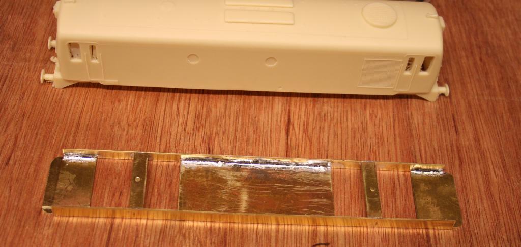
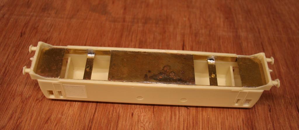
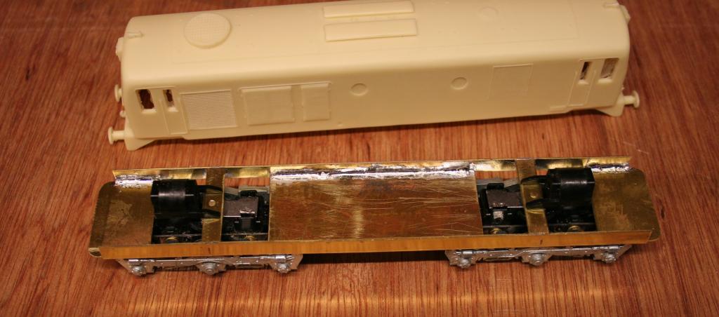
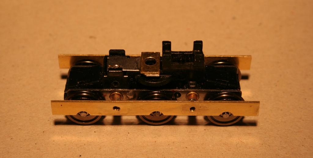
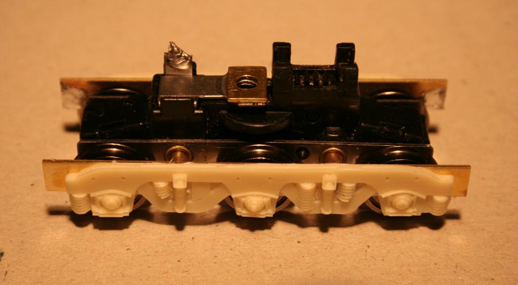
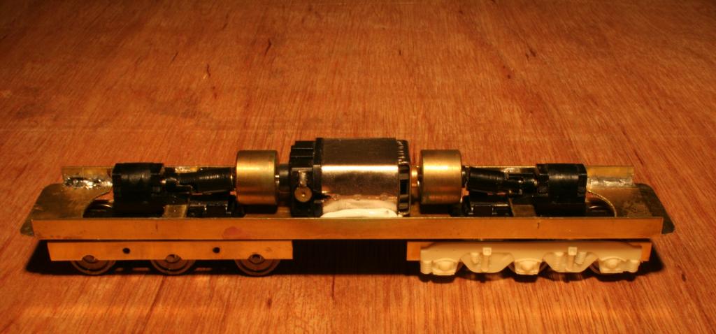
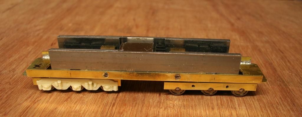
Much has been said over the last few months about a suitable chassis for the Silver Fox 001 Class kit, and the running qualities of the Lima/Hornby Deltic chassis. With an 001 Class kit waiting to be built, I decided not to take the easy option by using the aforementioned Deltic chassis, but to construct a chassis of my own. This was to have all wheel drive and pickup, flywheel motor and DCC sound. The project started by constructing a chassis frame out of brass. The floor was made from brass sheet, about 1mm thick, and the sides from 6mm brass strip. The floor pieces were cut to shape, to be a snug fit into the body, and the sides soldered on. The ends of the floor were shaped to the inside profile of the body ends, so that they rested on the lip behind the buffer beams. This meant that the bottom of the floor was almost flush with the bottom of the bodysides. Stage two was to prepare the bogies. They were originally from an Athearn SD40 loco, but the sideframes were from something else. A hole was drilled in the centre of what had been the Athearn swivel pad. A spacer made from a piece of 6mm brass strip was also drilled, and superglued to the swivel pad, ensuring that the holes lined up. The holes were then opened out to the size of the head of an 8BA screw, which would be the pivot pin. Two lengths of 6mm brass strip were cut to fit exactly between the sides of the chassis, and an 8BA screw fitted in the centre of each. The screws were cut flush with the top of the strip, and the heads on the bottom would become the pivot pins for the bogies. Once the required height of the chassis had been decided, the cross pieces were soldered in place. The bogies were then fitted to the chassis, and all dimensions checked. The bogie sideframes were removed, and a brass frame, using 6mm brass strip and brass tubing, fabricated for each side. These were then fitted to each bogie. The original Athearn wheels, which are notorious for getting dirty, were replaced with Bachmann plain disc wagon wheels, which are just about the right size. Although the Athearn bogies have the correct off-centre wheelbase for the 001 Class, the sideframes supplied with the kit do not. However, the difference is not too noticeable, and, despite the fact that I have a ‘thing’ about axleboxes not lining up with axles, I can live with the discrepancy. The sideframes were then tidied up, and bits that should not be there were removed. More bits made from plasticard will be added later, once the mechanical part of construction is fully finished, and the cosmetic part of construction is under way. The sideframes were then temporarily fitted to one bogie with double sided tape, the frame marked, and which has yet to be trimmed to shape. The chassis was then assembled, the motor being placed in a bed of silicon sealer using bits of plasticard under the flywheels to support the motor with about 1mm of silicon under it, until the silicon cures. This provides a good solid rubber mounting for the motor, and absorbs any vibration from it. If needs be, the motor can be easily removed at a later date, and refitted with fresh silicon. Any excess silicon can be removed by cutting with a craft knife. The motor is from an unknown Bachmann loco. The driveshafts are Athearn, with one end fitted with the end of a Bachmann driveshaft. The chassis was then fitted with some flat steel strip from B&Q for weight. This was cut to length and screwed in place. Countersunk screws had to be used as the sides of the chassis were a snug fit inside the loco body. Due to the width of the motor, there was only enough clearance for a single strip each side, but at the ends, clearances allowed a double thickness. The extra steel strips were fixed in place with superglue. Finally, the chassis was fitted with a 21 pin circuit board from a Bachmann locomotive, and a speaker in a suitably modified enclosure. The chassis was tested on DC, without a decoder, on a rolling road, and performed well with no excessive noise. The following road test on DCC was also very good, and the chassis (not yet fitted with couplings) propelled seven coaches up a 1 in 75 gradient with ease. It also traversed complex pointwork without any hesitation. More weight will be added once the underfloor fittings are in place, as I will fill the space in between with a solid lead block. Then we will see what it’s maximum hauling power is.

-
I have never been keen on common return track power feeds, and for as long as I can remember, have always used double power feeds to each track section. Since the Peco switch is only single pole, and I require at least triple pole switching, a relay has to be used. For improved electrical conductivity that does not rely on the point blades alone, each point frog also has it's polarity changed by the relay. In total, on this layout, each relay requires three SPDT switches. The other layout I mentioned required even more, as signalling is also involved in the switching process.
-
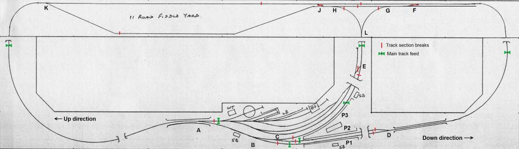
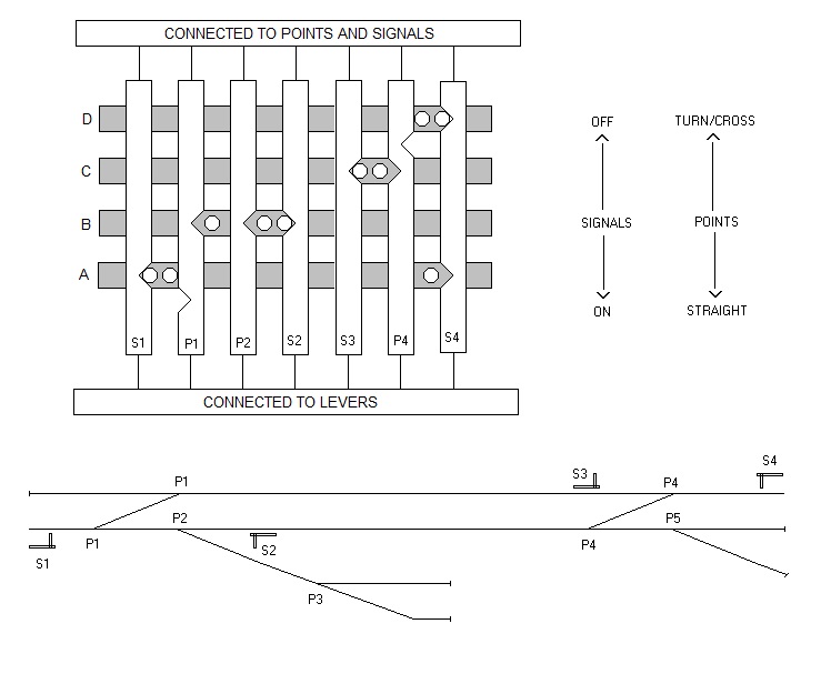
Creating sections of track and using switches to change controllers in those sections, known as cab control, means that by simply switching controllers in sections, a train can travel to any part of a layout using only one controller. The down side of this is that the operator has to remember to set all the appropriate switches before the move, and then set them all back once the movement is complete. Another way of carrying out such a move is to get the points to do the switching for you. A switch is fitted to the point motor, Peco do a switch that fits on to their standard motor which is perfect for the job. Some other makes of point motor come with a switch already built in. The switch is used to turn on and off a relay, which in turn changes controllers for a given section of track. The following diagram is for ‘Craigellachie’, a layout some of you may have seen at the recent Modelrail exhibition in Glasgow. This layout can have up to four trains running at any one time. One travelling in the Up direction, one in the Down direction, one on the branch line, and one loco shunting in the yard. The real station platform roads were only signalled for one direction running through the station, so a train will always take the left hand road between platforms 1 & 2. The branch platform, platform 3, is bi-directional. The main line is basically split in two. The right hand end is controller by controller 1. The left hand end is controlled by controller 2. Each driver only drives the train on his end of the layout. An Up train, which is using controller 1, will take point D into platform 1. A down train, which is using controller 2, will take points B & C into platform 2. Once both trains are in, and have stopped, point D is thrown. This switches on a relay which changes the feed to platform 2 from controller 2 to controller 1, ready for the right hand end driver to take the Down train to the fiddle yard. Likewise, when point B is thrown, a relay switches on and feeds platform 1 with controller 2 instead of controller 1, ready for the left hand end driver to now take the Up train to the fiddle yard. Once both trains have left, the points are reset, ready for the next trains, which switches off the relays, thus changing the controller feeds back to controller 1 for platform 1, and controller 2 for platform 2. The branch line uses controller 3, so as long as point C is set for the main line, a branch train will arrive in platform 3 on controller 3. If the train is a DMU or a Railbus, and is going back along the branch, nothing needs to happen, and the train can return to the fiddle yard on controller 3. If, however, the train in platform 3 is to continue it’s journey via the main line, when points B & C are set for platform 3, a relay switches on, and changes platform 3 to feed from controller 2 instead of controller 3. The left hand end driver can then drive the train in platform 3 to the fiddle yard via the main line. Likewise, a train travelling in the opposite direction from the main line to the branch line will use controller 2 until it arrives in platform 3, when, once point C is reset for platform 2, platform 3 will then revert to the control of controller 3. The goods yard uses controller 4 within the goods yard. When a Down goods train arrives, or an Up goods train is leaving, setting point A into the goods yard, will, via a relay, change control of the goods yard from controller 4 to controller 2, so the left had end driver has control of the goods yard. If, however, a goods train is arriving from, or leaving for the branch line, when point E is set into the goods yard, the goods yard then comes under the control of controller 3, providing point A is set for the main line. Point A always has priority over point E regarding controller feed to the goods yard. Arrivals and departures in the fiddle yard follow similar routing processes, with roads being fed by power from wherever the points are set to/from. A bit more complicated to try and explain. On the whole layout there is only one manual switch for changing controllers, and that relates to the main line at the left hand end. The track layout is exactly the same as the real station, but the real station had a fairly sparse train service, so the main line could be used for shunting goods trains. This means there is very little space at the left hand end of the goods yard for shunting. To overcome this in model form, due to the high level of main line traffic, the main line beyond point A to the entrance to the fiddle yard can be switched manually from controller 2 to controller 4, to enable goods yard shunting moves to be carried out. This switch can also be used to enable the loco on branch line loco hauled trains to run round their train via the goods loop, exactly as per the prototype. Hope all this makes sense. I figured ‘Craigellachie’ would be simple enough to explain, rather trying to describe a much bigger layout loosely based on Belfast York Road, which uses the same routing technology, plus fully working, and interlocked, colour light signalling.
-
Signalling is a fascinating subject, but to get it right, and to get it to work right can be extremely complicated. The following diagram is a simplified version of a signal interlocking system I drew up some years ago for an O gauge layout. In this version, only running line signals are shown, for simplicity there are no shunting signal or point locking levers shown. The advance starter and outer home signals are also not shown. The more signals there are the more complicated the interlocking. The bars are made from flat brass strip and fit into guides which are not shown. The white vertical bars are what link the levers to the points and signals, and they have notches cut into them. The grey horizontal bars are the interlocking bars, and they have raised cams fitted. The loops are only signalled for one direction running, so a train approaching from the left would take the crossover P1 into the upper platform. As shown on the interlocking diagram, crossover P1 is set straight, and the interlocking cams between S1 and P1 prevent signal S1 from being pulled off. Once point P1 is moved to the cross position, the notch in the slide bar will permit the cams to move when signal S1 is pulled off. Once signal S1 is pulled off, the slide bar will then prevent the cams from moving back, thus locking crossover P1. Signal S1 is also interlocked with signal S4, so that only one or the other signal can be pulled off, thus preventing two trains from arriving simultaneously. The same process applies to signal S4 and crossover P4. Once both trains have arrived, signals S1 and S4 have both been reset to stop, and crossovers P1 and P4 have both been reset to straight, along with point P2, then both signals P2 and P3 can be pulled off to permit departure. Again, by pulling off these signals, the movement of cams into notches prevents the points being changed until the signals are reset. I hope all that makes sense. I have tried to make it as simple as possible to understand.
-
Totally agree. The late 50s and early 60s were the best period for motive power IMO, with steam still on the go, and all the early generation railcars in operation. Halcyon days.
-
Looking through some old documents, I recently unearthed some useless information about 80 Class formations and liveries in early 1990. Whilst working in Portrush at that time I made some notes as part of research into the 80 Class with a view to building a set. The information may be of some use to someone. Power Car Intermediate Driving trailer Livery 67………………………...........732....………….Suburban 81..............764…………...736………….....Suburban 82……….......765……...……739……....…….Suburban 83………………………...........746 or 736…..Maroon/Grey 84……….......766……..…….738....…………..Suburban 85……….......762…………...742…....………..Suburban 87 M/G….....763 Sub…….744 Sub 89……….......769………..….743….....……….Suburban 91 M/G….....780 I/C……..749 I/C or 733 Sub 91 M/G….....773 I/C……..753 M/G 93……….......768…....…….734………......…Suburban 94……….......779…..……….747......…………InterCity 95 M/G….....774 I/C……..746 M/G or 753 M/G 96……….......780…..……….749…………......InterCity 97…….....…..776……....….751…......………InterCity 98……….......778.….……….754......…………InterCity 99……….......773 or 776..752 or 751.....InterCity Intermediates and driving trailers were swapped around on a regular basis.
-
Murphy Models are not all perfect. A 201 recently purchased kept throwing itself off the rails every time it came to a set of points whilst travelling with one particular end leading. Investigations revealed, with the help of a back-to-back wheel gauge, that the leading wheels of one bogie were almost 1mm over gauge. This was easily cured by removing the offending wheel set and pressing the wheels in till the correct back-to-back was achieved.
-
Thanks for the comments guys. Interestingly, to have an almost ready to run NIR coach that is easily obtainable, just get an Airfix/Dapol/Hornby Mk2d or Lima Mk2f 1st class coach, remove or hide the BR number and InterCity logo, renumber as 904, and hey presto, a genuine NIR coach. 904 ran in NIR service for a while still in BR blue and grey livery.
-
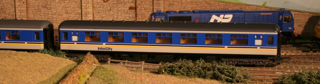
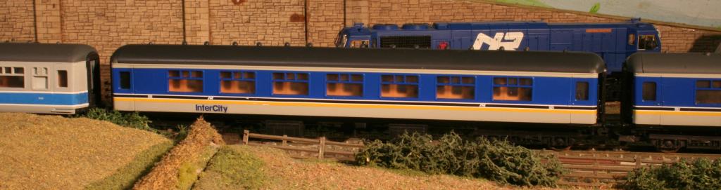
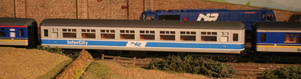
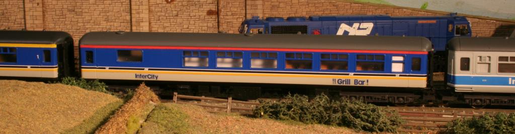
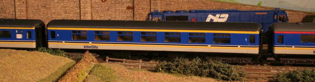
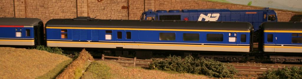
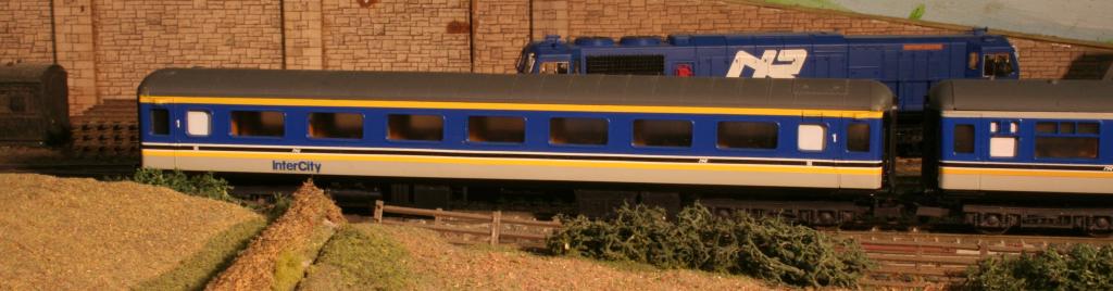
At last, finally on the home straight. Most of the batch of coaches are now just about complete, with just small touch-ups required, and a couple requiring numbering. Three are waiting for decals, and two are going back to the paint shop for stripping and repainting, due to unsatisfactory paintwork. Flush glazing to be fitted later. Generally very pleased with the results. Stripes decals are home produced, except for 904 which is Model Irish Railways. NIR, numbers and InterCity decals are from Railtec. The InterCity decals initially received from Railtec were too large for the full livery with the black band along the bottom, and were totally the wrong shade of blue. However, with a lot of communication with Steve at Railtec, the decals were revised, made smaller and the shade of blue changed. Full marks to Railtec. Ex FK, now Standard Class 922 SO Standard Open 932 Ex FK, now Standard Class 925 SO Standard Open in Enterprise/Intercity livery (experiment using one piece decal) Restaurant Car 947 FO First Open 901 Generator Van Executive Class 913, awaiting numbering Buffet Car 548, in Corporate livery, awaiting numbering FO First Open 904, partially numbered & waiting for number 4s
-
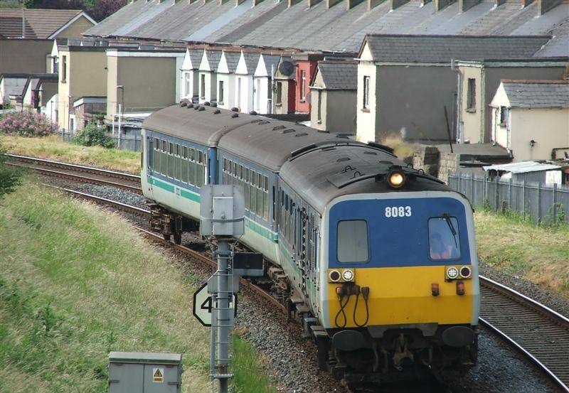
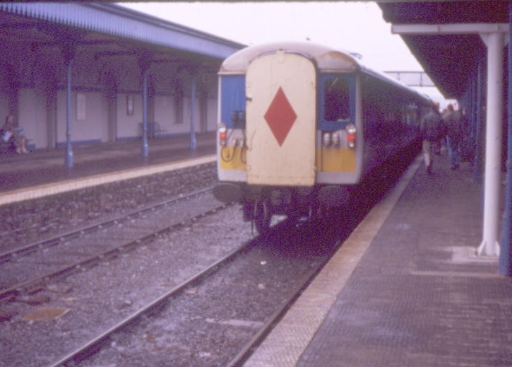
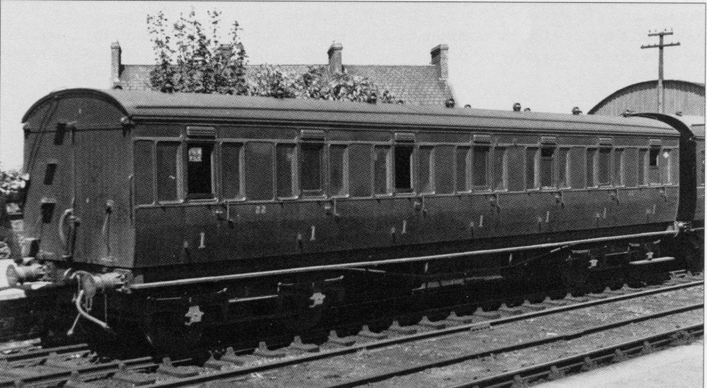
A little research has revealed that only one Enterprise driving trailer was converted for use as an 80 Class driving trailer, this being 754 (formerly 811). Pictures 1 & 2 are therefore of the same vehicle. Picture 3, however, raised another question. Why is the roof detail consistent with a brake vehicle, when driving trailers without a centre door 752 & 753 were converted from ex BR 2nd class open coaches? The answer, picture 3 is only the same vehicle as in pictures 1 & 2, it has had the guard’s compartment converted to passenger accommodation, thus now seating 75 instead of the original 31.
-
Some pictures of oddballs. The first two are not very good quality I am afraid. Driving trailer, probably the same one as picture 2. Not sure what the rest of the vehicle looks like. Ex Enterprise driving trailer, no centre door, centre car no centre door. Driving trailer and centre car with no centre doors.
-
Not necessarily, you could always model the vehicles that do not have the door. One or two ex Enterprise coaches were used to replace bomb damaged intermediate vehicles. There were also oddball driving trailers to be found. I remember seeing an ex Enterprise driving trailer complete with guards compartment, and there were one or two driving trailers without the centre door.
-
Most, but not all, driving trailers and intermediate coaches had a door in the middle, but the vehicles are of Mk2b design. The centre door feature was exclusive to NIR, to expedite speedier loading and unloading on suburban services.
-
The 80 Class were built using the BR Mk2b coach design. The Lima Mk2b 2nd class coach is a good donor for the driving trailer and intermediate coaches. The power car also requires a Lima Mk2b, but extensive butchery is needed.
-
Forgot to mention earlier. Under the UTA 1959 coaching stock renumbering, the coaches in question were renumbered as follows:- 20 renumbered to 467 21 renumbered to 469 22 renumbered to 351 23 renumbered to 275 24 renumbered to 343 25 renumbered to 345 26 renumbered to 349 27 renumbered to 347 With the exception of 24(343) and 25(345), all of these coaches were still in service in 1964. Withdrawal dates are not known for any of them.
-
The UTA numbers carried were 20 to 27 inclusive.
-
Whilst on the subject of Ratio coaches, the GNR purchased a number of ex LNWR coaches in 1947. Some of these were of a similar style to the Ratio kits, and the kits may be useful for ‘kitbashing’ some of these vehicles, although I have not done any research into the possibilities. Coach details are as follows: 472 L15 61ft Brake 3rd. UTA No 450 474 No details. Ex LMS 3474 477 K27 61ft 3rd Class. UTA No 302 478 K27 61ft 3rd Class. 479 K25 61ft 3rd Class. UTA No 300 480 K28 54ft 3rd Class. UTA No 304 I have drawings for the L15, K25, K27 and K28. If anyone wants copies, PM me.
-
I believe the photo was taken in 1949 on the BCDR section of the UTA, probably in Holywood, as there appears to be a centre road. According to my research, there were 8 ex LMS coaches of mainly Midland Railway origin purchased in 1948. After refurbishment they entered service between 1948 and 1950. Number 22 entered service in 1948 in crimson lake, whether LMS or NCC remains to be seen. The rest entered service in 1949 and 1950 in UTA green. 20 50ft Brake 3rd. In service 1949. LMS number 23216 21 48ft Brake 3rd. In service 1950. LMS number 22890 22 50ft 1st Class. In service 1948. LMS number 10513 23 50ft 1st/3rd Composite. In service 1950. LMS number 16936 24 48ft 3rd Class. In service 1950. LMS number 14102 25 48ft 3rd Class. In service 1950. LMS number 14104 26 50ft 3rd Class. In service 1949. LMS number 14222 27 50ft 3rd Class. In service 1949. LMS number 14226 According to the details given in the assembly instructions for the Ratio 3rd Class coach, the model is of a batch of coaches which includes numbers 24 and 25. The only differences appear to be different bogies, and simplification of the beading. The other coaches in the Ratio range are similar in style to the UTA coaches, the main differences being the length, and the bogies.
-
To be accurate, the coaches of this type were purchased in 1948 and were known as the 'Bain' coaches. They were not immediate replacements for blitz damaged stock. The subject coach is almost identical to number 22 which was a 1st class coach but of 50ft length. The Ratio coach is 48ft. In it's previous life it was 10513. The major change was to fit 5ft 3in gauge bogies. Still in LMS livery
-
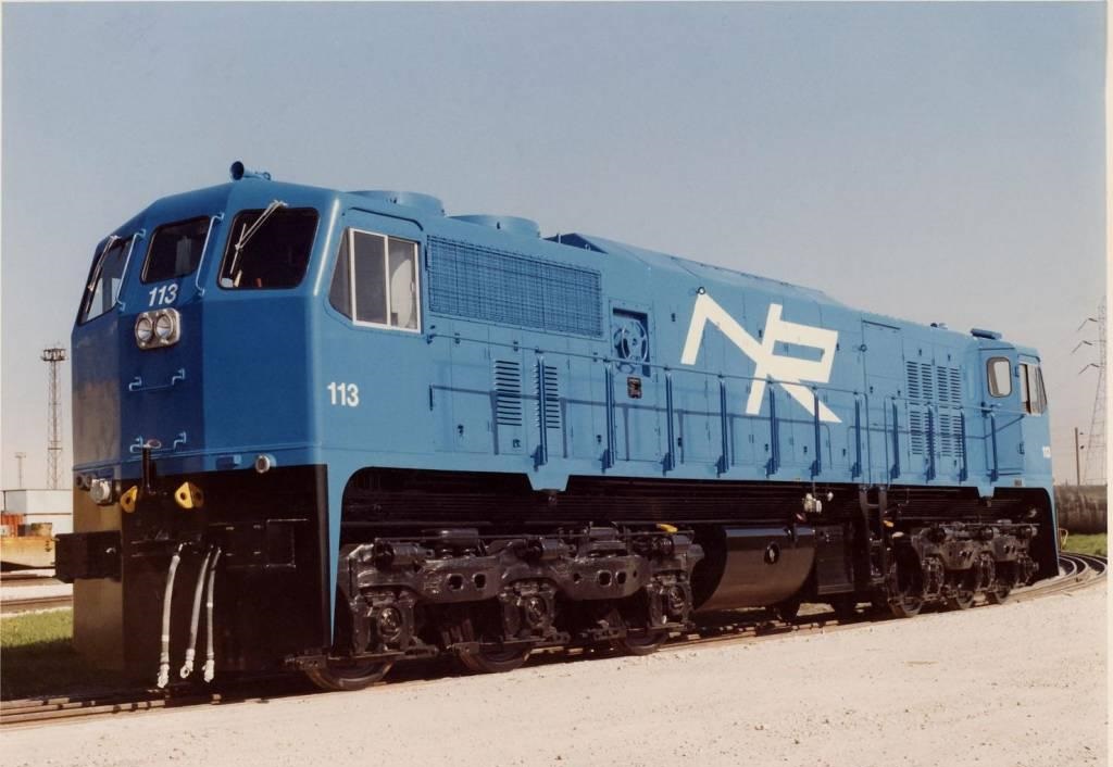
[/quote=Warbonnet;65509]Sensational pic. I saw a picture of one of the NIR 111s at La Grange in blue with no yellow end somewhere on the internet years ago. Cant for the life of me find it now! I think this might be the picture.
-
24 hours should have been adequate for stripping factory paint. Unusual for it not to come off. I assume you are using fresh brake fluid, and not some that has been opened and lying around for some time. If brake fluid is not stored in airtight conditions, it absorbs moisture from the atmosphere and loses its ability to strip paint. I have been using brake fluid for many years, with a 99% success rate. I have had the occasional wagon where the factory applied paint refuses to come off, but they are very rare. Trains from Jouef totally refuse to strip with brake fluid, but will readily wash off with white spirit. Very messy, and requires lots of white spirit, not recommended.
-
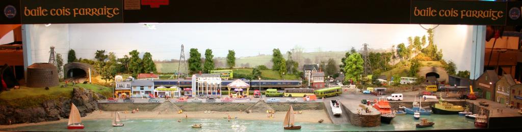
Thanks to all those who took the time to stop at stand 4C and chat, great to see you. I appreciate that on a one day trip to the show, time is limited. My apologies if anyone stopped, but I was not there, probably due to being on stewarding duties. It was a great show (certainly from the social point of view), although I was not able to pick up all the bits and pieces on my shopping list. Couple of pictures of the MRSI layout. Other show pictures to follow later. Full view of layout. A DUKW about to make a splash. If you visit Dublin, you have to take a 'Viking Splash' tour in a DUKW, it is the best city tour you will ever have.
-
I matched the Revell 52 paint with the real thing some 25 years ago, but I have always been a little bit concerned that maybe it was not quite right. However, once the MM locomotives appeared and matched the Revell 52 perfectly, I was over the moon. Even in the unlikely event of the MM colour not being exactly correct, at least my coaches do match them.