Dhu Varren
-
Posts
547 -
Joined
-
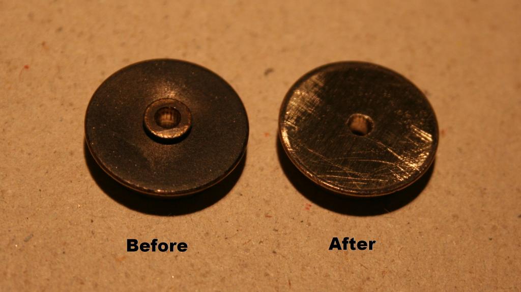
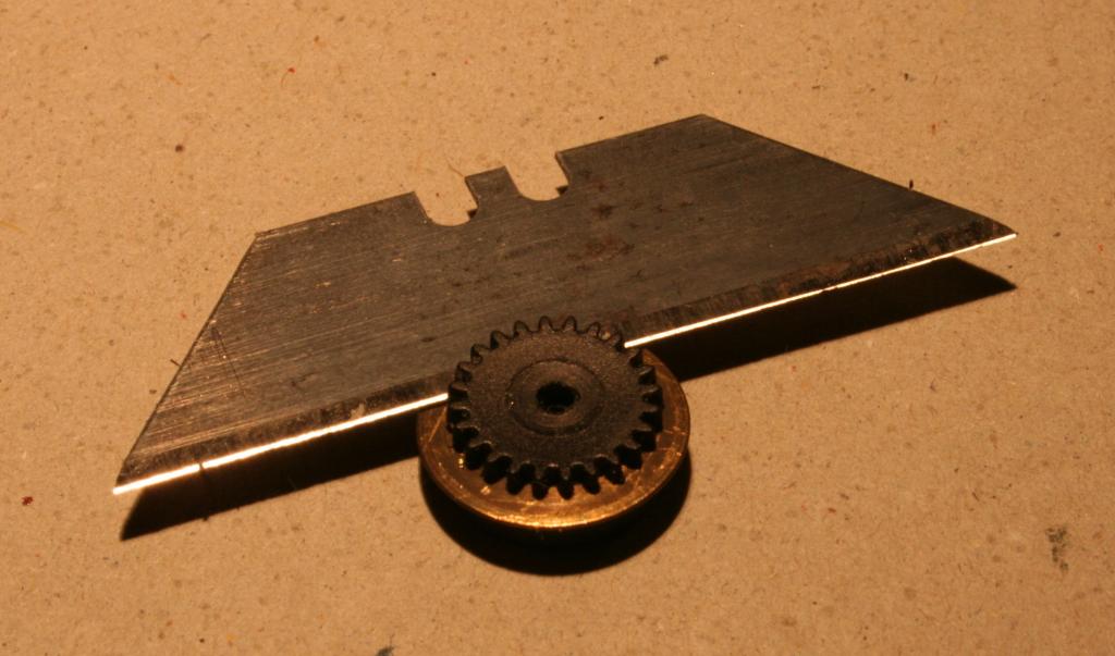
Last visited
-
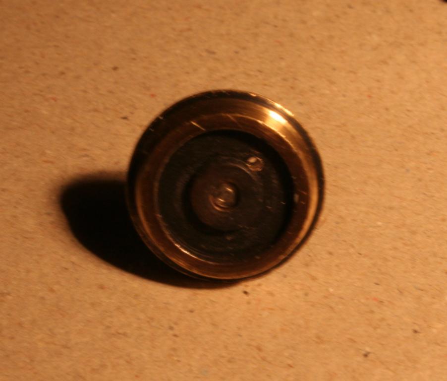
Days Won
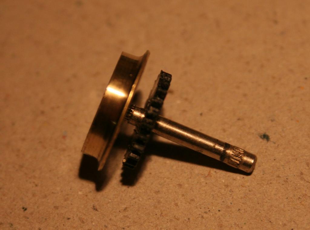
1
Content Type
Profiles
Forums
Events
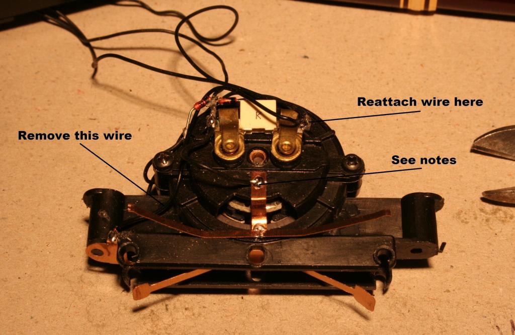
Gallery
Everything posted by Dhu Varren
-
Much has been said on this forum, rightly or wrongly, about the poor running qualities of Lima locomotives. It must be remembered that when the Lima 201 was produced, it was as good as you could get in British/Irish outline locomotives, and well before the ‘super’ all wheel drive, all wheel pickup and twin flywheel motored locomotives that we all take for granted these days. Twenty five years ago I ran a fleet of Lima BR locomotives, and at exhibitions, I was frequently asked how I got them to run so well. The answer was simple, modification. This post describes how to modify the Lima 201 to get the best out of it. You will need a back to back gauge to check the wheels after the modification. If you don’t have one, make one up using a piece of plasticard or brass, and adjust it till it fits between the existing wheels. You will also need two spare Lima wheel and axle sets. 1. Remove the body from the chassis. 2. Remove the two screws from the bottom of the power bogie. This will release the sideframes and allow the motor unit to be lifted out of the chassis. 3. Push the bulb at the motor end of the chassis out of its holder, this will give extra slack in the wiring. 4. Remove the drive wheels. They are a simple clip in fit, and will unclip easily by pulling downwards. 5. Remove both wheels from each axle using a suitable support and a drift. A blunted nail about 2mm diameter will do the job. A good hard knock will be required for the non-tyred wheel. 6. Using a sharp craft knife or blade, push it in behind the plastic gear and slice it off. The bit being sliced is only about 3mm diameter at the centre of the gear, so not much effort is required. Remove any excess plastic there may be left where the cut was made, ensuring the gear is flat on both sides. 7. Discard the wheel, having removed the tyre for reuse. (I retained the wheels, and when I had twelve, I turned them down to get rid of the tyre groove, reprofiled the flange, and used them to rewheel a complete loco, but that is another story). 8. Remove the raised boss on the back of the other wheel, using a file. I use a drill to remove most of the metal and finish off with a file. It is imperative that the back of the wheel is perfectly flat. 9. Gently knock the axle back into the wheel, till about 0.5mm short of flush at the front. 10. Push the gear onto the axle till flush with back of the wheel, it will be a good tight fit. It must sit flush. 11. Using a suitable support, drill a small hole through the wheel and gear, and fit a pin to lock the wheel and gear together. The size of the hole is dependant on the diameter of the pin you are going to use. The pin must be a good tight fit. Ensure the pin is flush at the front, and trim off flush at the back of the gear. 12. Remove the insulated wheel from the spare axle set, and fit onto the axle with the modified wheel. Ensure the wheel goes on straight. Roll the wheel set on a flat surface to ensure there is no wobble. Check that the back to back measurement is correct using the gauge. Lay the wheel sets to one side. 13. The centre axle does not need any modification. 14. The Lima motor unit, as it comes, collects current via the wheels on the opposite side from the gears. Because we have modified the axle so that the drive gear is now fitted to the pickup wheel, which is now on the opposite side, it means that the motor bogie is now picking up the opposite way round to the trailing bogie. The simple way to correct this is to disconnect the wire which connects the motor bogie pickup strip to the left hand brush holder, and reconnect it to the right hand brush holder. The wire will not be long enough to do this, so it needs to be replaced. No other wiring needs to be touched. 15. An extra pickup strip is now fashioned by making up a Z shaped piece of phosphor bronze strip to fit vertically as shown. At the top of the strip, a 90 degree bend is made, and trimmed to be 1mm long. The Z piece should be tinned at the bottom, for the pickup strip, and near the top for the wire, before fitting to the motor housing. The Z piece is then positioned and the 1mm tab is melted into the plastic with a soldering iron, making sure the Z piece does not foul the centre wheel. It will not cause any electrical problems if it fouls the wheel, but rather a physical problem on tight curves. A piece of phosphor bronze strip is then soldered to the bottom of the Z piece, cut to length, and bent as shown. If difficulty is experienced in fitting the pickup, it may be necessary to remove the centre wheelset, and refit later. A short length of wire is soldered to the Z piece near the top, and connected to the left hand brush holder from where the original wire was removed. 16. The trailing bogie already has four wheel pickup fitted, but on one side it is the centre wheel that picks up. There is no weight on that wheel, which I am not keen on, so I have fitted a pickup to the third wheel on that side, by soldering a piece of phosphor bronze strip to the back of the existing pickup and adjusted it to bear on the back of the third wheel. This gives the trailing bogie a five wheel pickup. 17. Refit the centre wheelset, if it was removed. Clip in the modified drive wheelsets taking care not to damage the new pickup strip, and that it is in position against the back of the wheels. Refit the motor bogie into the chassis, refit the bogie sideframe, refit the bulb, clean all the wheels and the chassis is ready to test. A job well done. 18. Due to the lack of traction tyres, the modified chassis will need extra weight. Many DIY stores like B&Q sell flat steel strip about 1 inch wide, which is very useful for weighting locos. My preferred option has to be Cerrobend, which is heavy like lead, non-toxic, and, best of all, it melts at less that the temperature of boiling water, so you can make a mould out of thick plasticard, or any other material, and cast your own weights to whatever shape you like. All my modified Lima BR locos were weighted with Cerrobend. I hope this will be helpful to someone. It is quite a straightforward job and does not take long. It has taken me far longer to compose these instructions, than it would have done to do the job. If you feel you are not up to being able to do this modification but you would like it done, I can do it on an exchange basis. You send me your chassis and payment, including return postage, and I will send you a modified chassis by return. PM me for details. If you are planning to visit Modelrail Scotland next week, and you let me know by midday Wednesday, I can have a chassis ready to exchange there, thus saving two lots of postage. I will be at the exhibition all three days. PM me if you are interested.

-
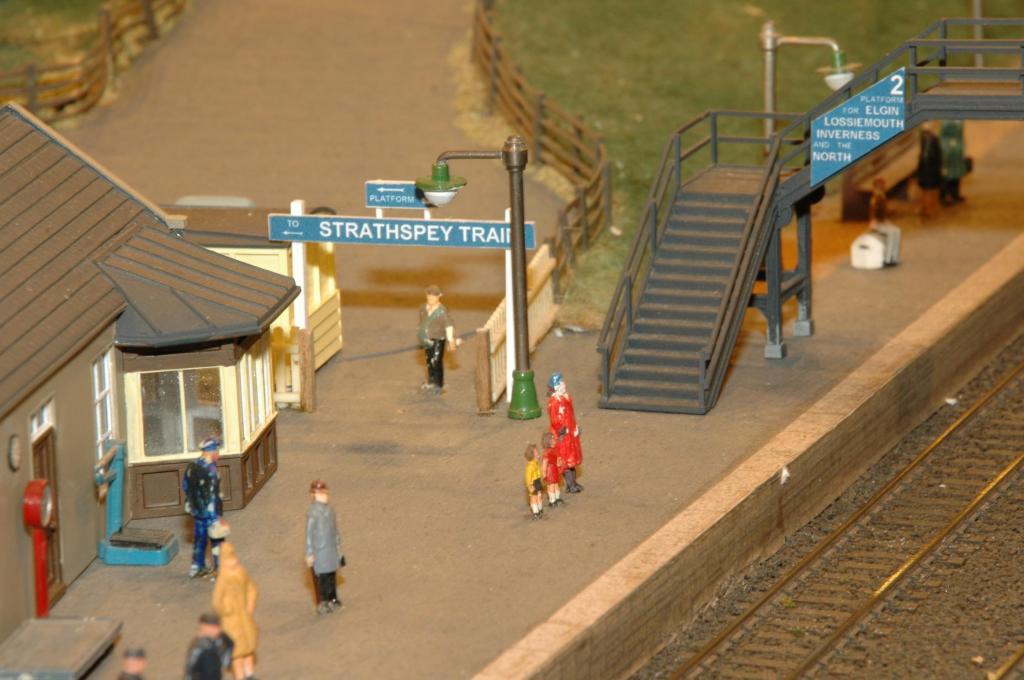
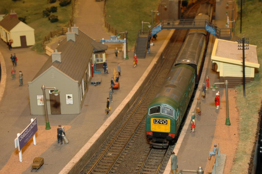
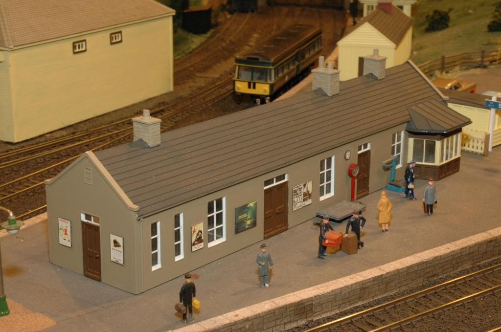
I will see what photos I can get. In the meantime, here are some preview pics of Craigellachie. Standard Class 5 arriving from Elgin and Park Royal Railbus (motorised Airfix kit) in Speyside platform. Station entrance on platform 2. NB Type 2 diesel arriving from Elgin on platform 1. Station building and goods shed with Park Royal Railbus at Speyside platform.
-
I believe the gradient at Yorkgate is the steepest on the network, if not in Ireland. In which case, according to http://www.translink.co.uk/Documents/Corporate/publications/Translink%20Network%20Statement%202015.pdf the gradient is 1 in 65.
-
Thanks to all for the comments. 913 is a scratch conversion from a Lima Mk2b Brake 1st. It is one of a batch of NIR coaches currently being finished off, and is just waiting to be numbered. There is also a lack of information regarding what the Executive interior looked like, so I am just going to have to make a guess, and update it later if anything materialises.
-
It is certainly a nice model, and a 'nice' price too. I just wonder how the little people get in and out, as there do not appear to be any door handles. A couple of boilers would not go amiss either.
-
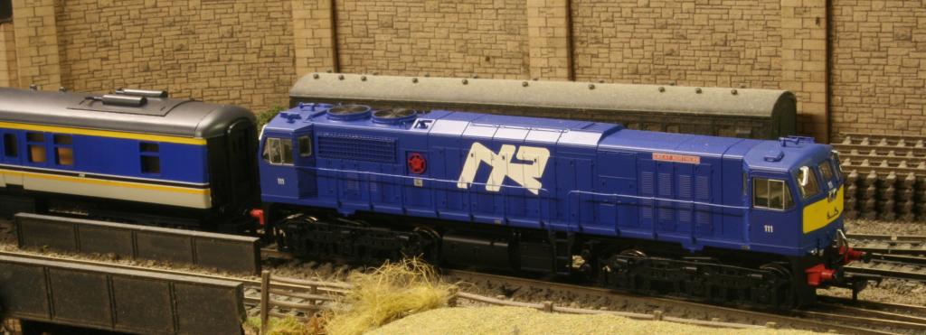
Finally took the bull by the horns and produced an NIR 111 Class No 111 in the dark blue livery. The model is a MM 8113 which has had the cabs resprayed to reduce the size of the yellow panels on the ends. 8113 was the only one of the three locos to have the large yellow panels. The paint used was out of the tin Revell 52, which matched the original MM colour to a tee. Railtec numbers were applied, but the Great Northern nameplate supplied on the Railtec sheet was just slightly too short to cover the original, so a new, slightly longer plate had to be made up. The coach is Brake Generator Executive 913 still to be numbered. The 'bumble bee' stripes were produced on a PC and printed on a laser printer, on to white transfer paper, and then carefully cut out using a new craft knife blade. A much cheaper option than purchasing.
-
According to E M Patterson's 1962 book on the GNR, the railcar colour is 'Royal blue'.
-
I have been watching this on ebay for some time now. Only curious to see how long it takes before the realisation sets in that it is not going to sell at anywhere near that price.
-

Installing DCC in DMU with 2 or more cars
Dhu Varren replied to DiveController's question in DCC, Electrics and Electronics
Kevin, The DBSO is not powered, and the pickups are purely for sound and lights. A speaker is installed in the DBSO. There is no connection between the loco and DBSO, the DBSO being treated as the second loco in a double headed consist, although at the other end of the train. Sounds other than the horn are also installed in the DBSO, such as a guard's whistle, doors slamming and brake squeal. Any sound is possible if you have a programmer. The sound decoder was one I picked up for peanuts on ebay, so the installation was not as expensive as it could have been. -
Installing DCC in DMU with 2 or more cars
Dhu Varren replied to DiveController's question in DCC, Electrics and Electronics
Although not a DMU, I have a ScotRail push/pull set with a sound fitted Class 47/7 at one end and a sound fitted DBSO at the other. They are both set up as a double headed unit so that lights are white at the leading end and red at the other when the leading vehicle is selected for driving. It also means that the horn sound comes from the correct end of the train, not such an issue with a two or three car DMU, but a must for a six coach push/pull. Phosphor bronze strip is used on the DBSO for pickup on every wheel, along with a bit of extra weight. The loco already has all wheel pickup and the weight. -
I would agree with Colm. It certainly looks like Ballyclare Junction. There is a good picture of Ballyclare Junction on P57 of 'The UTA in Colour' albeit without the footbridge.
-
As an impartial observer on this debate, as I have no interest in the Supertrain livery as such, it came to my attention, something I had never noticed before, that the Irish AC stock which has always been referred to as Mk2d, by railway publications and enthusiasts alike, is not that at all. The AC stock has, in fact, more in common with the BR Mk2f than the Mk2d. Apart from the suspect shade of orange, MM at least have got the physical side of things right, albeit the height of the windows open to question. All Mk2d coach bodies have both toilet windows on the same side. The Mk2f coach has toilet windows on opposite corners, except for the 1st class coach which has them both on the same side, as per the Mk2d. The air conditioning fitted to Irish coaches is the same as that fitted to the BR Mk2f, and can be easily identified by the single large fan unit on the underframe. The Mk2d and Mk2e coaches have a different system, which employs a twin fan unit. The Irish AC stock has all the Mk2f features, the standard class and composite coaches have toilet windows on opposite corners, and all types have the large single fan unit underneath.
-
Thanks for the info. George. Have only recently completed my white metal kit, but unfortunately it did not come with separate grilles, and I have never managed to find any suitable ones, but I am always looking.
-
You have done a great job on the 071 George. I assume the resin moulding is the same as the white metal version, it certainly looks the same. Can I ask what top grilles did you use, or are they part of the moulding. The top grilles of my white metal version just do not look right.
-
Excellent. Lovely job.
-
Hear hear. Back then, due to the lack of it, we were encouraged to scratchbuild or kitbash to produce Irish rolling stock. We seem to have moved into an era of 'out of the box' modelling. This, of course, will produce the familiar cry of 'I don't have the skills to do that'. We all had to start somewhere, if you don't try, you don't succeed. I have to admit that some of my early builds were a bit suspect, but they did look like a representation of the prototype, and practice makes perfect. I still have some of my early models, and I still scratchbuild/kitbash where possible, even though a RTR model may be available.
-
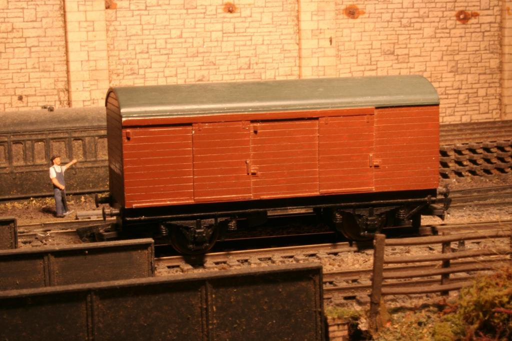
Been looking for suitable chassis for brown vans. I have discovered that the chassis fitted to the old Hornby Dublo LWB 'Brown Van', the open wagon, and the horse box, is a suitable candidate with a cut & shut. The chassis is also fitted to a couple of Wrenn wagons. With a 17mm chunk cut out of the middle to shorten it, and then spliced, the resulting chassis is a scale 24 feet, with a wheelbase of 15 feet. All that is needed then is to fit brake levers and a bit of brake rigging. With correct size 14mm coaching stock wheels fitted, it certainly looks the part. Another, better but harder to get hold of chassis, is the Hornby Dublo or Wrenn SR Utility Van chassis. This chassis is easier to work with as it is plastic, but the conversion is the same. A larger chunk has to be taken out, as the chassis is longer, but the end result is the same as the diecast one, 24ft length and 15ft wheelbase. Below is a picture of a brown van using the plastic chassis. Still requires the brake detail fitting.
-
Modelling 546 without an interior is an option as a last resort, if no information is forthcoming. However, if possible, it is nice to get it right, visible or not.
-
I am currently finishing off a batch of NIR Mk 2 coaches in InterCity/Corporate livery, but I can not find any information about the interior layout of the Mk 2f 'Grill/Bar/Dining Car' 546. I am also looking for details of the interior of the Executive Brake Generator Van 913. The only information I have on 913 is that there were 'loose chairs' as required, but no numbers or types of chair. Any information on either of these vehicles would be greatly appreciated.
-
Nice pictures. The first picture is not technically part of the Harbour lines, but is in fact the Oxford Street terminus of the erstwhile Belfast Central Railway. This closed to passengers in 1885 due to competition from the Belfast street tramways, and the BCR was absorbed into the GNR(I). The connection to the Harbour lines was through a tunnel under the Queens Bridge, top right of the picture. The lines at the bottom of the picture went to Maysfield Junction, a short distance away, close to the site of the present day Central Station. The road running left to right of the picture is Oxford Street. The road in the centre of the picture alongside the river no longer exists as a road.
-
Old Lima Class A - what's it worth ?
Dhu Varren replied to aramand's question in Questions & Answers
Good to hear somebody is taking the bull by the horns, although it does seem a shame to carve up a good IR liveried body. If anybody is interested in having a go at a conversion, I have a number of scrap Lima Class 33 bodies just crying out to be converted. Just send me a PM. -
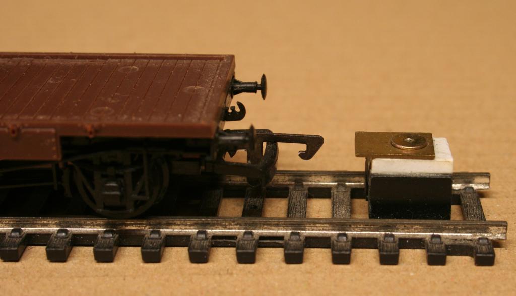
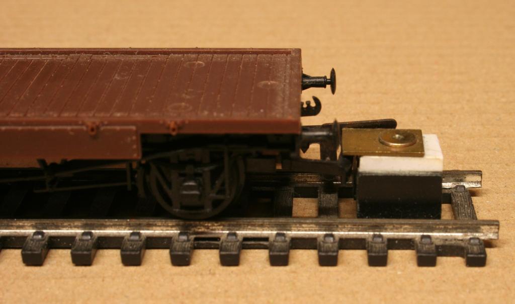
Consistently getting the correct height for couplings has always been a problem. For tension lock couplings, the height of the top of the bar is the critical dimension, as different makes of coupling have differing depths from top to bottom. Whilst Kirley’s gauge is one way of dealing with the problem, it does not take into account the depth of the bar, from top to bottom. Using plasticard, I made up a gauge which measures the height of the top of the bar, and works for any make of tension lock coupling. With this gauge I have used a piece of brass at the top, but plasticard works just as well. The plastic block made from the plasticard, is only about 10mm wide, is glued to the piece of track and offset away from the hook to allow it to pass down the side of the block. The vehicle is pushed up to the block, the hook passes it, and the coupling bar should just pass under the top plate.
-
Most Lima locomotives post 1986 have wheels with a less coarse profile which will run fine on Peco code 75 track and points. Earlier locomotives had a wheel profile with the 'pizza cutter' flanges, which do not run. Similarly, more recently produced coaches and wagons were fitted with less coarse profile wheels which are quite happy on code 75 track. As mentioned in DC's thread above, Lima coach and wagon axles are shorter than most other axles, and fitting Jackson Romford replacement wheels to the original axles is the simple solution, once the uninsulated Lima wheel is persuaded to leave the axle. Another option that I use, is to remove the replacement wheels from the axle, filing off one end of the axle to reduce the length to that of a Lima axle, putting the axle in an electric drill and filing a new tapered end, finishing off with some fine abrasive paper.
-
This mixture does match the Precision paint colour as well. It was the Precision colour that I used initially, but the ban on sending even small quantities of paint by post in the UK led me to find a local source of paint.
-
Revell No 30 mixed 50/50 with Revell No 85 gives a nice satin finish orange, which is a good match with MM Cravens coaches.. Railtec Transfers also have a good range of Irish transfers, including the broken wheel logo.