Dhu Varren
-
Posts
547 -
Joined
-
Last visited
-
Days Won
1
Content Type
Profiles
Forums
Events
Gallery
Blogs
Everything posted by Dhu Varren
-
Yes it is correct. Railcar A suffered damage during shunting in 1963 at one end, and was sold to a contractor who removed the bodywork from the damaged end, fitted lifting gear and winches and used it for dismantling the Clonsilla Jct to Navan line. It was also used by the same contractor to dismantle 'The Derry Road' in 1966.
-
Actually, looking further into it, the livery is in fact the NIR blue and cream livery used on the GNR section for a while. The leading railcar is 131 of which there is a colour picture of it, in this livery, in 1966 on P22 of Norman Johnston's excellent book 'Parting Shot'.
-
The railcars are actually in the early NIR maroon and ivory livery, not GNR blue and cream.
-
Not AEC units, but BUT units.
-
They are certainly not 1/87, they are bigger than that. On the basis that the box trailer is as near as damn it, a scale 40ft, they are as near 1/76 as you are going to get.
-
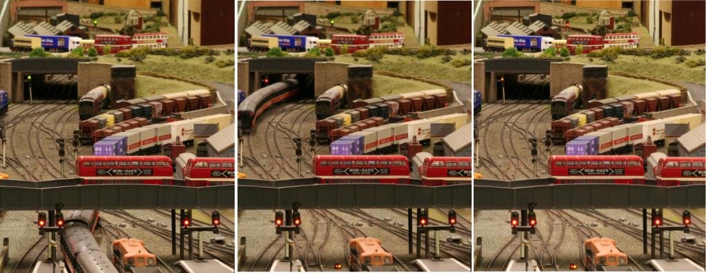
If you look closely at the picture, you can see that the train is formed of two four car sets.
-
I don't know the exact scale, but they look fine with other 1/76 (00) scale vehicles. The box trailer measures 57mm, which equates to 39.25 feet in 00, which is close enough to 40ft for government work.
-
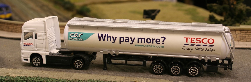
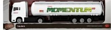
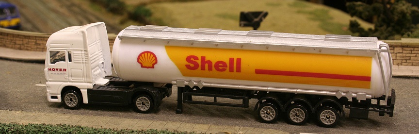
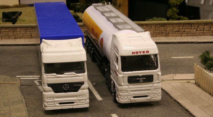
Tesco do a couple of cheap trucks which are ideal for tarting up, or converting to something better. The are the right size for 00, and sell for £2.00 in the UK, or E2.99 in ROI. There are two trucks, the first a Mercedes tractor unit having a 40ft articulated box trailer, and the second a MAN tractor unit with a 40ft tank trailer. There have been two versions of the tank trailer, the first being in Tesco Fuel livery, the second, and current version being in Momentum Fuel livery. The livery detail on each truck is on self adhesive stickers, and is easily removed, leaving a good surface for replacement decals. I have a number of these vehicles waiting to be dealt with, with one livery change shown below. The wheels are not ideal, but could be changed for something better, or toned down a bit with less garish paint. I have done the wheels on the Shell tank with silver paint, but even that is not ideal. The Shell tank has decals produced on a PC and printed on decal paper. The tractor unit has Hoyer decals, again printed on a PC, Hoyer being the distribution company for Shell in the UK.

-
The sound programme is my own and was compiled, and the sound decoder programmed, using a Lokprogrammer. A friend was a great home video enthusiast 30 years ago, and has hours of BR video recordings that he made. The horns are recordings of NIR horns, which may or may not be appropriate for Hunslets, but are better than the Bachmann 20 horns. As far as the chassis is concerned, there are two variations. One has an 8 pin DCC socket, the other a 21 pin connector. If it is sound fitted it will have the 21 pin connector, if not sound fitted, it could have either. The 8 pin chassis does not have a place for a speaker, so one would have to be created by physically rearranging the chassis and fittings. I did this with one of my Hunslets which utilises an 8 pin chassis. Known 21 pin chassis locos are 20034 and D8158. 8 pin chassis 20052. Hope this helps.
-
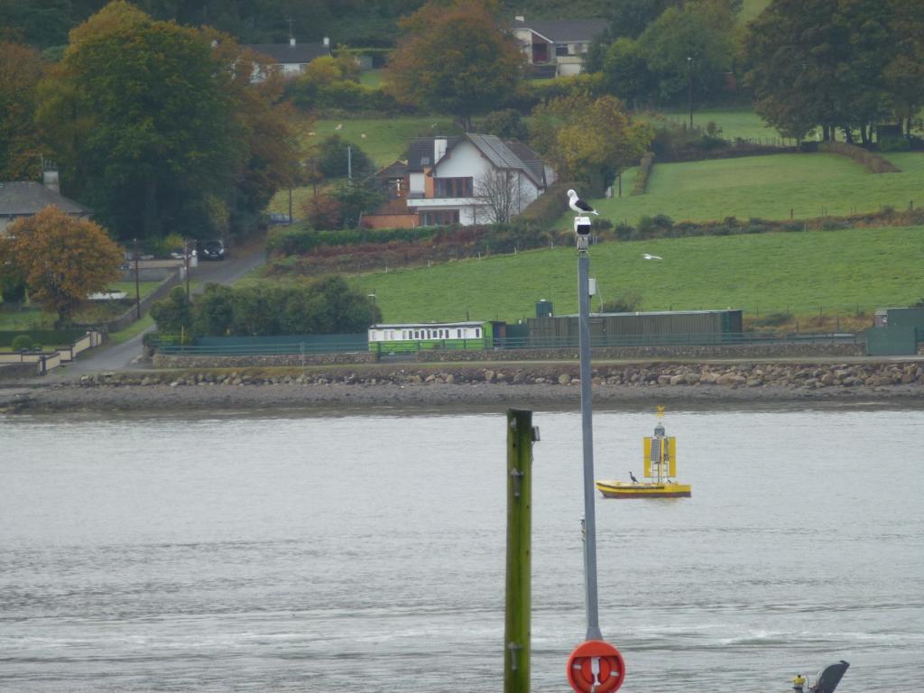
Thanks for that info JHB, but according to my map, Gyles Quay is much farther South round the coast. This carriage is directly across the water from Warrenpoint, at Drummullagh. No doubt it also has the same origins as above.
-
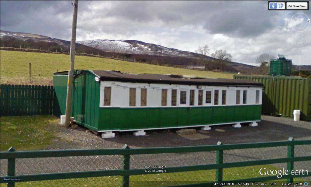
On a recent visit to Warrenpoint, I noticed what appeared to be a railway carriage across the water near Omeath. I then went onto Google Earth, and found said carriage, which turned out to be a grounded coach body, roughly where the trackbed of the old DNGR used to be. Does anybody have any idea of the origins of this carriage?
-
Kevin, the Hunslet sounds just like a 20, so I was told by Jim Edgar of Markle Video, so I have all three of my Hunslets fitted with 20 sound. I am not so sure about horns though, and I have used NIR horn sounds recorded from various sources. The Hornby 20 appears to be the basic Lima version with minor changes, such as a DCC socket, and pickups fitted to the driving bogie. The tyres on the driving bogie have been reduced from four to two, so there should be a slight improvement in running with the extra pickups. I don't know about pulling power though. Certainly the overall running qualities would not be a patch on the Class 55, which has been totally revamped with a new motor and drive, plus pickups on all twelve wheels.
-
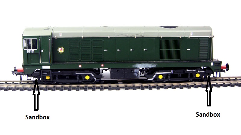
Kevin, the sandboxes and pipes on the Bachmann 20 are separate parts fitted to the bogie frame, and normally can be prised off quite easily, depending on how much adhesive has been used. What remains can be pared off with a craft knife. Having said that, one of my 20 chassis had got sandboxes which are part of the bogie frame moulding, and which are more difficult to remove cleanly. Another tip when fitting the body to the chassis. The NIR Hunslet was a very tall loco compared to Mk 2 coaches, and the kit makes the model look extremely tall. I found that by lowering the body as much as possible on the chassis makes a much more acceptable height. To do this requires the removal of the battery box detail from the chassis. The battery boxes are separate plastic parts glued to the metal underframe, and can be prised off, with care if you want to reuse them. I sold mine on ebay. Removing the battery boxes will allow the body to sit lower. The kit body should have more correct underframe detail as part of the moulding. Next, to allow the body to sit lower, some of the resin inside the roof will need to be scraped away to clear the DCC connector, and, if it a sound fitted chassis, some material will need to be removed to clear the speaker. The roof is quite thick where material needs to be removed, so there is no danger of scraping through. I used a craft knife with a chisel blade to cut and scrape away the resin, which is not as difficult as it sounds. The end result is well worth the effort.
-
I very rarely buy new locos, apart from Murphy Models, and have never had any problems that were not mentioned when buying. The 20 bogies are as close as you are ever going to get with a RTR loco. They are of the correct pattern, but the wheelbase is slightly long for a Hunslet. There is also the issue of the sanding equipment. The Hunslets did not have any, but the 20 does.
-
Kevin, the Bachmann 20 chassis is the option to go for, and can be obtained reasonably cheaply on ebay, if you are prepared to bide your time. Be prepared for some surgery on ths chassis to get it to fit into the body. I have all three Hunslets, two Silver Fox and one Model Irish Railways. My first Hunslet, a Silver Fox took the chassis without any modification at all to the chassis. The second, a secondhand MIR, came complete with chassis, which had had surgery, but too much taken off, and I had to add about 3mm to it for a snug fit. My third, another Silver Fox had to have about 0.75mm shaved off the chassis for it to fit.
-

4mm scale 'WT' rebuild from a Fowler 2-6-4T
Dhu Varren replied to Richard EH's topic in Irish Models
I would agree with Horsetan. I am in the early stages of building a WT, and have replaced the 4P wheels with the larger Black 5 wheels. The only thing that needs doing is to adjust the brake gear so that it does not foul the larger wheels. I have also replaced the front pony and rear bogie wheels with correct size smaller wheels. The original 4P wheels are too big for a WT. Again, the correct size wheels all round, make all the difference to the appearance of the loco. -
Leaf fall was not such a problem in steam days, as more control of lineside vegetation growth was done to reduce the risk of fire caused by steam locos, and hence, less leaves on the line. Halcyon days.
-
I have been using 'Bachmann 36-017 Metal Disc Brake Type Wagon Wheels' These are 13.7mm dia, almost 40", and although they are supposed to represent wheels with disc brakes, the brake disc is barely noticeable. They are also easy to come by, and can be made to fit most axles.
-
UTA buses at a bargain price. http://www.ebay.co.uk/itm/EFE-16009-00-SCALE-Leyl-Titan-PD2-Lowbridge-Double-Deck-Bus-Ulster-Transport-/111829870521?
-
My chosen method, which I have used for more than thirty years, is to build the baseboard with a plywood, chipboard or MDF top, my preference being 3/8” plywood. On top of the plywood is ½” wood fibre insulation board, softboard as it is sometimes known, pinned down and covering at least where the track will be. On top of that, cheap 1/8” cork tiles from the local DIY shop are glued down, and trimmed once the track is laid. The track is then pinned down using Peco track pins, which go into the cork and softboard quite easily, but are retained securely by the cork. Once the track is correctly aligned, ballast is applied dry in the traditional way, and dilute PVA dripped on using an eye dropper, ensuring that the PVA only settles on areas covered by the cork. The combination of cork and insulation board ensures that noise is kept to an acceptable minimum, although there will always be a certain amount of noise even where there is no ballast.
-
Recently had reason to take a quick trip to Dublin by train, and noted the two pairs of Gatwicks plus Generator van still rotting away at Lisburn. However, also noted the other two pairs languishing at Dundalk, with the Translink logos painted out. Has anyone any idea why the Gatwicks at Dundalk are there?
-
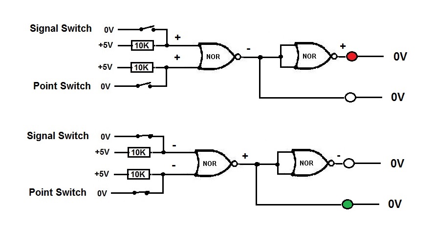
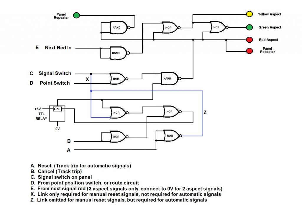
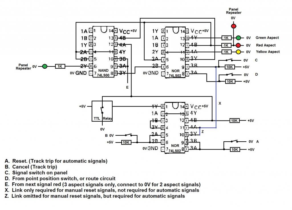
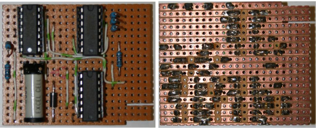
Second part. The signalling system uses TTL technology based on circuits that were in a book on electronics for railway modellers. TTL is transistor logic where the output from a circuit is either + or -, Hi or Low, 1 or 0. The terminology depends on how you think. They all mean the same. TTL circuits work on 5v DC, and an output is classed as Hi if it is greater than 3v. Conversely, an output is Low if it is less than 2v. These figures are not the exact values, but just give an idea. TTL outputs are controlled by ‘gates’ of different types. There are ‘AND’ gates, ‘OR’ gates, ‘NAND’ gates, ‘NOR’ gates, and ‘INVERTER’ gates. Each gate can be considered as an electronic switch, the output of which depends on the input(s). The INVERTER is the exception as it has only one input, and is used to invert the output to the opposite of the input. So a Hi input will come out of an INVERTER gate as a Low output, and vice verce. When initially reading the aforementioned book, I just could not get my head round what it was talking about with ‘AND’ & ‘OR’ gates. It was only when my daughter came to me in desperation with her homework as she had to come up with everyday scenarios where AND & OR situations arose. This had nothing to do with electronics but it made sense when applied to TTL gates. An everyday situation is when either the driver’s door of a car is opened, OR the passenger door is opened, the interior light comes on. Likewise, when the ignition switch is turned on, AND the wiper switch is operated, the wipers work. The list is endless. Applying that to signalling, an AND gate with an input from a switch on the panel for a signal, and an input from a switch on a point will give an output to a proceed aspect LED when both inputs are Hi. Should either of these inputs be low, then the LED will not light up. TTL gates are like building with Lego, only you have to draw out your plan on paper for the circuit. Once that is done, it has to be translated into a physical plan for the installation of the ‘chips’ and how they will be wired/connected together on a circuit board. Most TTL ‘chips’ have four gates on each, although the ‘inverter’ has six. There are also ‘chips with gates with more than two inputs, the number of gates on one of these ‘chips’ depends on the number of inputs to each gate. For instance, three inputs will only give three gates, and so on, as there are only twelve pins available on each ‘chip’ for gates. In addition, there are two pins for the 5v power supply. Surprisingly, NAND and NOR gates are the most useful. They function just like AND and OR gates, only the output is inverted. They can also be used as INVERTER gates simply by connecting an input to both input connections. TTL chips are very robust, and can take a lot of punishment when connecting up, particularly where a short circuit situation arises. A very useful tool, particularly for fault finding, is a Logic Probe, which will indicate which type of input or output, Hi or Low, is present at any connection. Each signal on the layout has a plug in circuit board. These boards are standardised, and can be used for either 2 or 3 aspect signals. The 4 aspect boards are also standardised, but can only be used for 4 aspect signals. Each signal board has inputs from the panel switch, from the points (via a points circuit board), from the track treadle and from the next signal red aspect, and in the case of 4 aspect signals, from the single amber of the next signal. There is also an input from the track treadle of the signal after the next signal, which releases the first signal for resetting. To show how simple the circuitry can be, the circuit below is for a basic 2 aspect signal with a panel switch, and an input from a point switch. Both the panel switch, and the point switch must be closed for the signal to show a green aspect, if either one is open, then the signal will remain red. If there were more than one point protected by the signal, then a multi gate NOR chip could be used. The switch inputs are held Hi by means of a 10K resistor. When a switch is closed, it connects the input to 0V giving a Low input. Being a NOR gate, if either input is Hi then it gives a Low output, which will not light the green LED. However, the second NOR gate, wired as an inverter, will invert the Low output from the first gate, to a Hi output, which will light the red LED. Conversely, when both switches are closed, both inputs are Low, giving a Hi output which will light the green LED, but the second NOR gate will invert that Hi output to Low, which will not light the red LED. I hope that all makes sense. The next pictures show the gate plan for a 2 or 3 aspect signal board, and the physical layout of the chips on the board with wiring. There are spare unused gates on this board, which could be utilised for controlling a feather attached to the signal, or even a ‘calling on’ light. Note the use of NAND and NOR gates as INVERTERS which does away with the need for an INVERTER chip on the circuit board. Picture of a completed circuit board, front and rear. The right hand edge of the board is designed to slot into an edge connector, vary useful for fault finding in that identical boards can be swapped round to determine if the fault is with a board, or with wiring elsewhere. There is a TTL relay included in the circuit, which is what the track treadle activates when the signal is passed. The relay locks on and holds the signal at red until it is reset either by the panel switch or the treadle for the next but one signal, depending on whether the signal controlled by this board is an automatic one or not. Flip-Flop switches were originally used for this purpose, but it was found that locomotives produced too much electrical ‘noise’ which affected the Flip-Flops, which then gave spurious outputs. The TTL relays were substituted, and have worked perfectly ever since. There is an extra component on the signal board, not shown on the plan, namely a diode across the coil of the relay, to dissipate any Back EMF generated when the relay unlatches. If the power supply to the layout is switched off for any reason, any signals that are still showing red due to being cancelled via treadles will return to a proceed aspect when the power is restored. This is due to there no longer being any power to hold the relay closed, so it opens and the signal is released.
-
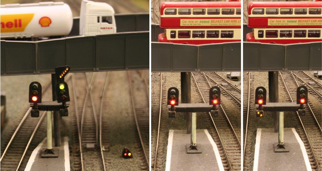
Watching “The Derry Road’s” Interesting thread on signalling ‘Rachelstown & St Stephens Green’ reminded me of a signalling project I undertook twenty five years ago, and which is still working well. The layout is a large terminus station and loco depot, which are approximately 35 feet long, before the tracks disappear onto double track running behind the scenes. This length gives the opportunity for some 4 aspect colour light signalling. The signals are a mixture of Eckon signals, and scratchbuilt signals to look like Eckon signals. They were fitted with LEDs at a when Eckon were still using bulbs. The signals were also built before the advent of white LEDs, so, as a compromise, yellow LEDs were used where white lights were required, such as feathers and shunting signals. All signals are controlled by 3 position switches. The centre position is the signal ON, showing the stop aspect (red). The down position is the signal OFF, showing a proceed aspect (amber, double amber or green), depending what aspect the next signal is showing. The up position switches on the appropriate calling on signal, if fitted. The passage of trains cancels each signal as the train passes (returns to red) by means of a treadle in the track. Magnets and reed switches were considered, but decided against, as a treadle will work with any vehicle. All signals, except 4 aspects will stay red until the switch is returned to the centre position, moved back to the down (OFF) position, and the train has passed two more signals. 4 aspect signals reset themselves automatically after the train has passed two more signals, showing first a single amber, then a double amber, and finally a green. Signals are interlocked with the points on the route the signals control, so that if any point is not set for the route, the signal cannot be pulled OFF. As this layout was originally an exhibition layout, it was decided that points should not be interlocked with signals. This was to ensure that should there be a signal failure, the layout could still operate, albeit without signals, until the fault was sorted. The first set of pictures show from left, Platform 5 starter with calling on unlit. Platform 4 starter showing green with feather, and a calling on unlit. The ground signal is showing stop. There seems to be a bit of red light leakage into the top led, never noticed that before. Platforms 3 & 2 showing reds and calling ons unlit, and then Platform 2 with the calling on signal OFF. These signals are all scratchbuilt. Platform 1, not shown, has a simple 3 aspect starter with calling on. The second set of pictures shows the full length of the layout, with the starter signals nearest, the advance starter signal in the middle, and the first 4 aspect section signal in the top centre. Apart from the starter signals, all the others are standard Eckon signals with LEDs, plus calling on signals where necessary. The pictures show the sequence of events as a train departs, and once the signalman has pulled off the signals, everything is done automatically, with no further input from him. From left, all signals are ON. Next, Platform 4 showing amber plus feather. Then advance starter showing amber, and P4 starter showing green with feather. The section signal has gone straight to green, which allows the advance starter go to green. The train leaves P4, the starter changes to red and the feather goes out. As the train passes the advance starter, it also changes to red. Lastly, the train has passed the section signal which has gone to red, and then the next signal, not shown, has been passed which has released the advance starter, which now shows amber. With a bit of cunning circuitry, the section signal will work it's way back to green, via a single amber which will let the advance starter go to green, then a double amber, and then the green. The third set of pictures show, from left, the home signals all ON. Then there is the outer home signal, which is scratchbuilt, showing an amber as the following home signal is red, and the feather for the second crossover. Next are the home signals, with that for Platform 3 now showing an amber. There are no green aspects on the home signals, as the next signal is permanently red, the buffer stops. Back to the outer home signal which now shows a green, as the Platform 3 home signal is now showing an amber aspect. I hope this shows what can be done with a signalling system, and a bit later on I will be putting together a piece on how the system works electrically, which will really frazzle your minds.
-
The first Lima Class 37, 37012 Loch Rannoch, in blue with white stripe, first appeared about March or April 1986.
-
The BR and IE Mk3 coaches were all built on the 8 window format plus two small windows just inboard of the doors, including the catering vehicles. The Cu Na Mara coaches are only distant cousins of the Mk3, and have a different profile with nine windows plus two. To convert any of the RTR Mk3 coaches, Lima, Hornby or Jouef to Cu Na Mara stock would require major surgery to fit nine windows into where eight windows already exist. A possible easier, cheaper option might be to use the original short Hornby Mk3 as a donor, and do a 'cut and shut'. These old Mk3s are readily available cheaply on the secondhand market, but there are two versions available. The original short version introduced in 1977 had only seven windows, which are spaced much the same as the Lima, Hornby and Jouef scale length Mk3s, so a 'cut and shut' using this version would only give an eight window coach. However, in 1984 Hornby revised the short Mk3 coach giving it eight windows in the same short length as the previous version. It was not until 1999 that Hornby introduced the current, scale length Mk3 coach. The theory is, and I have not got any short eight windowed Mk3s to confirm this, that a 'cut and shut' using the short eight windowed Mk3 would give a nine windowed coach, which could then be passed off as a Cu Na Mara vehicle.