Dhu Varren
-
Posts
547 -
Joined
-
Last visited
-
Days Won
1
Content Type
Profiles
Forums
Events
Gallery
Blogs
Everything posted by Dhu Varren
-
PECO code 100 track is identical to Hornby track in terms of rail height, and is fully compatible. The track geometry is totally different in term of radius, but you can mix and match without any problems.
-
Likewise. And it shows up well the inside rail chair keys. Keep posting the pictures Tony.
-
If you are building a freelance layout, you could probably use the Market yard as inspiration, and modify it to suit your requirements.
-
There is a picture in Desmond Coakham's 'Irish Broad Gauge Carriages' on P94 of NCC number 24 after the rebuild mentioned above, but in UTA green. There is also, on P93 a picture of NCC number 22 in rebuilt form, but still in LMS livery. The kit produced by Ratio for an all 1st coach is almost identical to number 22, and certainly would be a suitable donor for an NCC/UTA version. The sides for Ratio coaches used to be, and maybe still are, available on their own for cut & shut projects. Just contact Ratio direct.
-
Pictures in Eric Challoner's 'Farewell The Derry Road' on P128, clearly show inside keys on plain track, and outside keys on pointwork.
-
I would suggest than the Omagh North Cabin area is a bit big to be able to fit into the dimensions you have mentioned, to create a worthwhile layout, however, something like the Market yard would probably be more suitable. I don't have any track details for that location, but pictures show at least four sets of points.
-
Great pictures Tony. They bring back many memories. The second picture is too far away to show up the inside keys, and the resolution is too small to blow up clearly, but if the first picture is blown up, it quite clearly shows the change from outside keys, to no keys on the outside.
-
Realtec Transfers do transfers for GNR AEC railcars including numbers and crests. The crests would suit loco hauled stock as well. They also do a sheet of goods wagon numbers and letters. If you need something not listed, Realtec will produce transfers for you, if you provide samples of what you want. They are very helpful in that respect. http://www.railtec-models.com/scale-model-transfers.php?gauge=4mm®ion=2
-
It has to be remembered that the Market Branch was a very short, freight only, slow speed line, so perfect track was not a necessity, unlike the main line to the right. The branch was accessed by means of a ground frame, just to the right of the turnout and off the picture. It was unlocked by the use of the train staff. I presume there was a staff machine somewhere on the branch, to allow use of the mainline while there was a loco on the branch.
-
There is a picture of ex LMS coach 14102 still in LMS livery in 1950, in Mark Kennedy's 'The LMS in Ireland' on P79. It carries the NCC number 24. Ratio Kits do a model kit of this exact coach, which also happens to be exactly the same as NCC number 25. Apart from the bogies, the picture in the book is exactly what the Ratio kit looks like, but at some point, under the UTA, all the beading below the top waist beading was removed. The ends were also replaced with straight matchboarded ends. These coaches were built in 1908, purchased from BR in 1948, and were still in service in 1964. The official withdrawal date is not known to me.
-
Something I noticed back in the 1960s when staying with relatives next to the junction, to the right of the photo, that the rail chair keys on the branch, were on the inside of the rails. Something I had never seen before, or since. If you look closely at the photo, this can be seen. The track in front of the loco is of the conventional 'outside the rail' key, but changes to 'inside the rail' just behind the second bogie wheel. Ah, fond memories.
-

What is this piece of electronics for?
Dhu Varren replied to Kirley's question in Questions & Answers
Looks like a Hornby Zero 1 chip to me. -
A metal boiler on a 4-4-0, particularly a small one like a U class, would cause even more running problems by making the loco even more nose heavy, unless some sort of suspension is incorporated between the loco chassis and the bogie to keep the nose up. However, a metal boiler can only boost the pulling power of a 6 coupled loco such as an 0-6-0 or 2-6-0.
-
I had a cab ride in an MPD set, circa 1959, from Derry to Belfast, during which there were a number of token exchanges between Coleraine and Ballymena, at speed, using tablet catchers. Quite spectacular close up.
-
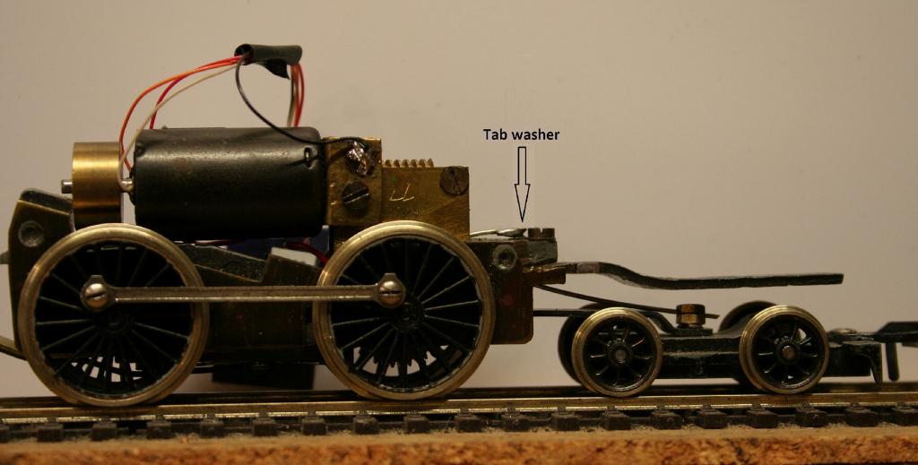
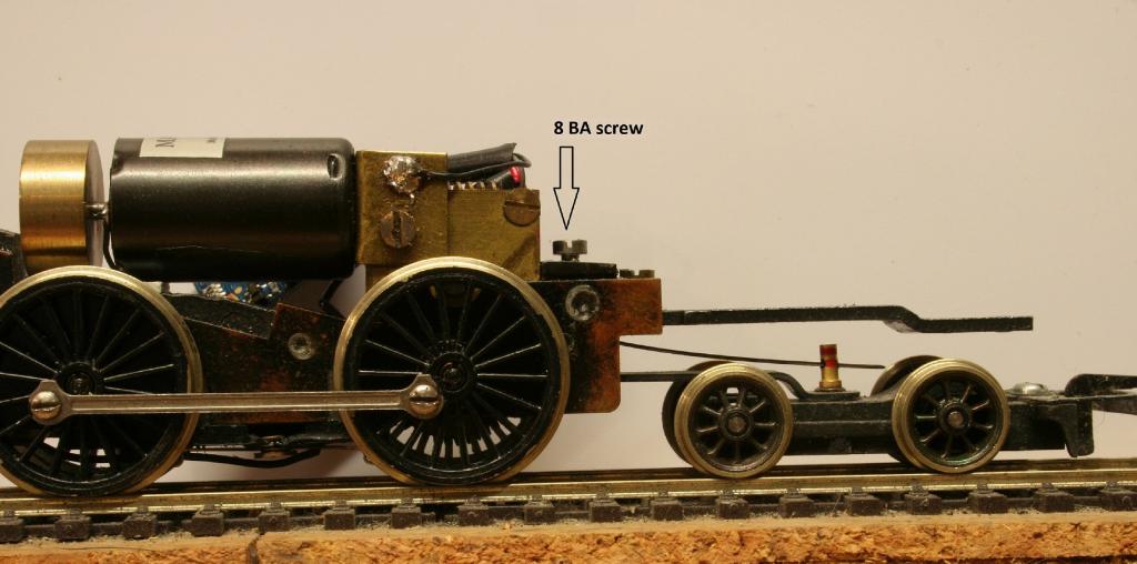
The arrival of the OO Works GNR(I) U Class 4-4-0 has certainly opened a can of worms regarding the running qualities of what is a superb, and expensive, RTR model of an Irish prototype. For the money paid, one would expect the model to be a superb runner, as well as a superb looker. Not having seen one of these models in the flesh, I don’t know how easy it would be to fit extra pickups to both the locomotive and tender, but from the photos I have seen, it would seem to be fairly simple. The second issue is the weight distribution problem. 4-4-0s are notorious for having poor pulling power, and being front end heavy. They also have a tendency, due to the short rigid wheelbase, for the front end to wiggle from side to side, even when running on straight track, and for a massive front end overhang when traversing pointwork and curves. My solution to the weight distribution problem, also addresses the ‘wiggle’ and overhang problems. All my 4-4-0s are fitted so. The examples shown are old Tri-ang Hornby 2P 4-4-0 chassis fitted with Romford wheels, Mashima motors and 44-1 gearboxes. A piece of nickel silver wire, or thin piano wire, is used as a vertical spring, and also acts as a lateral bogie centraliser. A hole, big enough for the wire, is drilled either vertically, or horizontally, in the chassis. The wire is inserted in the hole, and secured rigidly. For the vertical hole, I have soldered the end to a tab washer, which is secured by the chassis extension bar fixing screw. For the horizontal hole, a second hole is drilled vertically, tapped for an 8BA screw, which secures the wire. I would assume that a liberal application of superglue, or careful use of epoxy glue could do the same job, but I have no experience of this, as I prefer a 'mechanical' solution. At the bogie pivot, which in my locos is a hollow rivet, a suitable pin is made up. In one example, an 8BA screw with a nut as a spacer is used. A hole is drilled horizontally through the head of the screw, large enough to allow the wire to slide freely in it. Note that the pin is only sitting in the pivot hole, and is not rigid. The wire is centralised simply by bending, and then adjusted vertically by bending, until the required amount of vertical support is achieved. You can keep adding weight and adjusting the wire until you are satisfied with the resultant pulling power. The horizontal centralising qualities will allow the bogie to guide your loco into curves, just as the prototype does.

-
With a rear overhang like that, it has to be a 2-10-4 'Texas' locomotive.
-
Kevin, you can't change just part of the sound installed on the decoder, you have to reblow the whole thing, which means reinstalling ALL the sounds, which means you need a complete Class 20 sound project, which is where you can put in horns/whistles etc. of your choice.
-
Unfortunately, the Lokprogrammer cannot alter the sound program on a decoder. To make any changes, you need to have the original sound programme, amend it, and reblow the decoder. For GM locos this is easy to do, as NIRCLASS80 says, you can download a suitable sound program from ESU, amend it as required, and load it onto a Loksound decoder. Apart from GM locos, BR locos are not available from the ESU library.
-
Correction to the above link http://irishrailwaymodeller.com
-
I have to confess to being a little confused with this thread. I don't have any answer to the problem, but, according to my documentation for the Loksound V4.0, CV27 is for Brake Mode, and CV51, along with 52 to 56, is for Load Control.
-
The mule is not self propelled, it is cable hauled.
-
The original light blue is very close to Ford Electric Monza Blue.
-
According to the Hornby Service Sheet for R2183A, there is no DCC socket fitted, but it would be easy enough to 'hard wire' in a decoder. http://www.hornby.com/us-en/downloads/view/download/item/15
-
MSE (Model Signal Engineering) do a range of signals and components. They do etched brass components for somersault signals and I am sure they would also have lower quadrant components suitable for GNR(I) signals. http://www.modelsignals.com/4mm_scale_frame.htm
-
Information on Irish registrations on Wikipedia:-