Dhu Varren
-
Posts
547 -
Joined
-
Last visited
-
Days Won
1
Content Type
Profiles
Forums
Events
Gallery
Blogs
Everything posted by Dhu Varren
-
The train is comprised of Mk 2a & b coaches which, being ex BR, have a different electrical system to the Mk2d coaches of IE. Three Dutch Vans were converted from steam heat to electrical generators to run with the Mk 2a & b coaches. Presumably two Dutch Vans were required in the formation in the clip, due to the number of coaches.
-
I have never used the Dapol semaphore signals, but from what I have read, all that is required is a momentary power connection , or pulse, to operate the signal. The simplest way for operation is a push button. The first press of the button moves the signal one way, the next press moves it the other way, and so on. The Peco point switch provides two such pulses, one for each position of the lever. Unfortunately, as it stands, this is no use whatsoever for the Dapol signals. However, today I dissected a Peco point switch, to see how it operated, and discovered that if the two outer terminals are connected together and then to one wire from the signal, and the middle terminal is connected to the other wire, the Peco switch will provide one pulse to the signal each time the lever is moved. By an ingenious lever mechanism, the pulse only happens towards the end of the lever movement, so it is very unlikely that the signal will get out of sequence with the lever, as the lever has to be moved fully before the pulse is created..
-
It is sometimes better to have a slightly wider gap than that left by a razor saw, particularly where the gap is used for isolation purposes. In hot weather the track can expand sufficiently for the gap to close and cause a short circuit, or continuity where it is not required. Last week's hot weather did exactly that on an automated layout in a museum I am involved with. A train on a certain track kept overshooting it's stopping point, and a second train would ram into the side of it, causing a derailment. Investigation into the control equipment did not reveal any fault, and it was purely by accident that the closed up rail joint was found. Once the joint was opened up again, all trains ran normally.
-
Whilst admiring Nelson’s excellent work on the brown van, I happened to notice that on one side the doors opened to the left, while on the other side the doors opened to the right. Having assumed for many years that all the doors opened to the left, and never having seen anything to the contrary, I decided to do some research. I looked at dozens of pictures of brown vans, and in none of them did any doors open to the right, which I thought was a bit strange. Surely all the pictures cannot be of the same side of so many different vans. There was, however, one exception to this, and that was the recently restored brown van at Whitehead, which has doors opening to the right, at least on one side. I then checked a drawing which I have, and lo, the drawing shows doors opening to the left on one side, and doors opening to the right on the other. Now we all know how inaccurate drawings can be, so could it be that in this case, since I have not found any pictures showing doors opening to the right, that the drawing is incorrect, and the restorers have restored the brown van at Whitehead as per the drawing, and Leslie’s brown van kit is based on the restored van. I am sure, and hopeful, that someone will come up with an answer to this.
-
Judging by the contents of the sets, these would date from the early 1960s.
-
Just checked a servo on a baby GM. Plenty of room above the coupling pocket, but care would be required in routing the thread so that it does not foul the buffer beam. There is also room underneath the pocket, but the servo would be visible from the side, although a touch of black paint would help to hide it. Better on top I think.
-
I would say that there is an error in the description for the 6 pack. The six pack would seem to be a multiple pack containing enough parts to fit out three locos (6 couplings). I would also suggest making the connection to the function output on the loco circuit board, rather than the decoder. Much less expensive if you make a mess of it. I still have a 2 pack left from the original installation, so I will have a look at the implications of installing one in a baby GM. The friend I did the work for moved away shortly after the installation in the 2-6-4T, and left me with a second loco to do. I had said I would not start the second installation until after he provided me with a suitable decoder, which he hasn't so far. That was nearly three years ago.
-
Noel, having installed two of those setups, I can't see any reason for any wear or chaffing to occur. After all, there is next to no tension required to pull the coupling open, and certainly, on the installations I did, there was no contact with anything to cause wear or chaffing. In the extremely unlikely event of the thread breaking, it would be easy enough to replace it anyway. I would have no hesitation in using that system, if I was using Kadee couplings.
-
I hadn't seen that type before. Below is a link showing the type I fitted. The servo can be fitted anywhere as long as it is 90 degrees to the coupler. It operates by pulling on a length of fine thread.
-
A couple of years ago a friend asked me to fit DCC remote uncouplers for Kadee couplings to a BR 2-6-4T locomotive. I don't use Kadees myself, but once I had installed the necessary servos and carried out functional tests, I found it was brilliant. Being able to uncouple a locomotive from stock, anywhere on the layout, was fascinating. No magnets required. I tested the loco for hours, just to make sure it worked, you understand..
-
I had the same problem a few years ago, getting paint of a suitable shade. Below is a link to my original question, and the results.
-
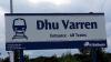
Pre war nostalgia on the NCC
-
I just used 5 thou plasticard cut to shape and size, and glued in position with solvent. When totally set, the hole for the grille was carefully opened up and filed out, leaving a thin surround. A grille was then fitted into the hole.
-
I don't have any actual dimensions for the added headstocks. It was simply a case of taking measurements from photographs, and adjusting the ends of the model until they looked right. If it is any help, I have made my extensions 5.5mm each end.
-
Interesting circuit. But what happens when the red loco reaches the crossing first and is on the crossing when the green loco activates the stop circuit? I think a 'first come, first served' circuit would be a better option.
-
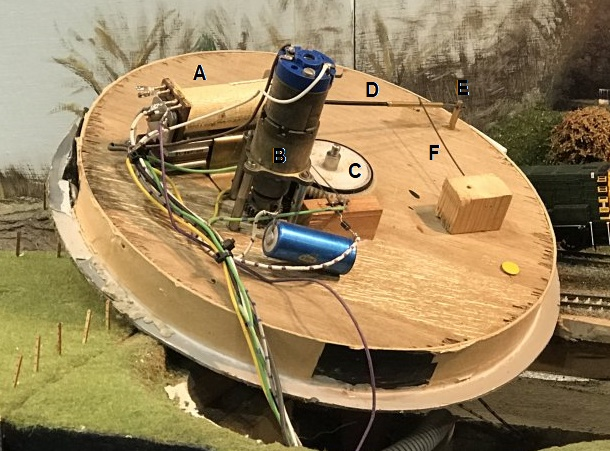
How it works Bear in mind that the mechanism is upside down in the picture, so down in the text means up in the picture, and so on. The turntable consists of 3 main parts. The turntable deck. The deck is not rigidly attached to the centre spindle, but lightly rests on a brass plate, which has two pins sticking up which engage with two holes in the bottom of the deck. It is then secured loosely to the plate with a shouldered screw. The deck is therefore free to follow any fluctuations in the level of the pit without binding. The weight of the deck, and locomotive, are carried on the four wheels which run on the circular rail round the outside of the pit. The turntable pit. The floor is made from a circle of 9mm plywood to ensure there is no warping. It is edged with card to form the pit. The operating mechanism. The Relay The Motor & Gearbox. The Control Board Relay Arm Extension The Locking Pin. 3mm brass rod. The control board is a disc of copperclad paxolin with two 2mm isolated strips 180 degrees apart, which line up with the point at which the turntable should stop. Underneath the deck at each end is a flat brass strip, across the width of the deck, with a 3.2mm hole at the centre point of each strip. Pin E rests in this hole to ensure that the deck lines up correctly, and does not move. Wire F acts as a spring to ensure the pin enters the hole quickly. Also underneath the deck are two phosphor bronze pickup strips which contact two brass screw heads in the pit near the centre. These provide power to the rails when the deck is lined up, but lose contact once the deck starts to move. This prevents a locomotive moving during the turning cycle. When the start button is pressed, the relay A closes and Switches on power to the motor B. Switches on power to itself via the control board C (which is missing in the picture. The white disc is actually the last gear in the geartrain. The control disc fits on the spindle below the gear) to keep itself switched on until completion of half a revolution of the turntable. Rod D is rigidly attached to the relay arm and the end at pin E moves down to pull Pin E out of the location hole in the bottom of the turntable deck, thus allowing the deck to move. Once the deck has started to move, the pickups on the disc will contact the copper part of the disc, and supply power to the relay to keep it on. On completion of half a revolution, the pickups on the disc enter the isolated strip and cut the power to the relay. The relay starts to open, but the pin E rises slightly and hits the brass strip on the bottom of the deck thus preventing the relay opening fully. The deck continues to rotate until the pin enters the hole, which allows the relay to open fully and cut the power to the motor. The deck stops and the pin ensures the deck is correctly aligned and will not move. Power has also been restored to the rails, and the loco can drive off.

-
Nice picture Joe. Didn't realise you had taken a picture while I was trying to fix the contact disc, which is missing in the picture.
-
The turntable is a heavily modified Airfix kit, with the deck turned upside down, and then motorised. It was built more than twenty years ago and at Glasgow developed a fault in the electrical/mechanical system for controlling the rotation, due basically to wear and tear. Unfortunately, since it had been so long since I built it, it took me a while to figure out how exactly how it worked. Once that was figured out, it was fairly straightforward to repair.
-
Some Youtube footage of the layout, Newtontoll, including the working turntable which had caused so much trouble on the Friday after only a couple of hours use on the Friday. Now working fine. From 19.30 on. https://www.youtube.com/watch?v=NnjSHlbrSA8
-
Just back home after an exhausting three days working and exhibiting at Modelrail. Good to meet numerous familiar, and some not so familiar faces, including Patrick and Fran of the IRM team who were wandering about. Did not get to speak to them, as I was otherwise engaged at the time. For those who found me repairing the turntable on the Friday, it worked flawlessly for the rest of the show. Thanks to everybody who stopped to chat.
-

Derry - Coleraine Train stops for plane!
Dhu Varren replied to GNRi1959's topic in What's happening on the network?
This will be your train then JHB. Ballykelly airfield closed completely in 2009. All runways are marked accordingly. -
Derry - Coleraine Train stops for plane!
Dhu Varren replied to GNRi1959's topic in What's happening on the network?
A case of mistaken identity? http://news.bbc.co.uk/1/hi/northern_ireland/4857962.stm -
Derry - Coleraine Train stops for plane!
Dhu Varren replied to GNRi1959's topic in What's happening on the network?
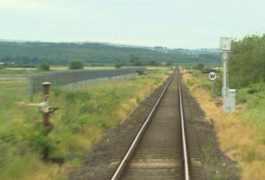
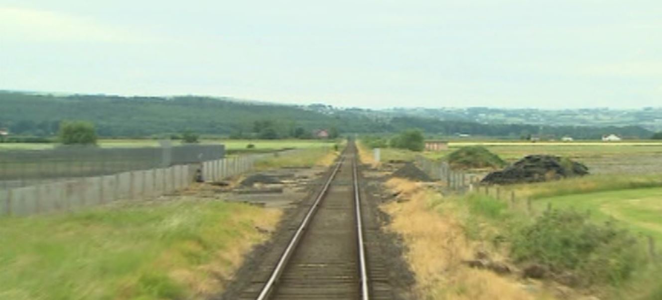
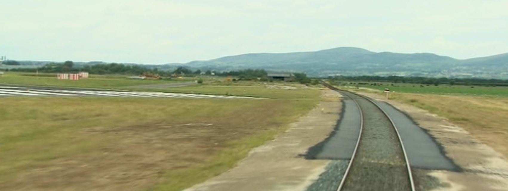
There must have been a reason for giving the aircraft priority, as Air Traffic Control work in conjunction with NIR to ensure there are no trains due before giving permission to land. Ballykelly RAF airfield, just a few miles east of City of Derry Airport was in the same situation before it closed. The runway was lengthened during WW2, across the railway, and the railway thereafter crossed the runway on a level crossing controlled by semaphore signals on very short posts, which can still be seen today, albeit without the signal arms. Trains there had priority except in an emergency. I believe it was the only place in the world where a railway crossed an active runway. Ballykelly. Old somersault signal post on left of picture. Ballykelly. Runway crossing as it is today. City of Derry Airport runway threshold. The railway does not actually cross the airfield, it is outside the unfenced boundary, but the track is roughly paved in case an aircraft lands short of the runway.
-
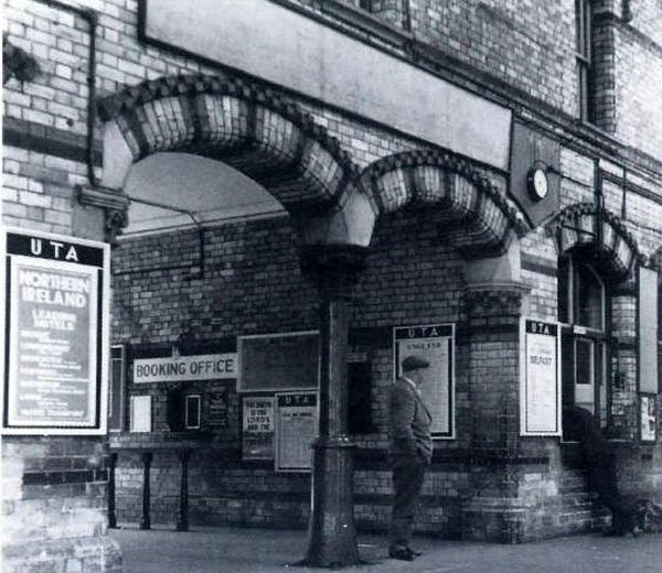
Found this picture on the internet. Also found some more at https://www.geograph.org.uk/snippet/9157
-
You could always compromise and have the best of both worlds by having a fiddle yard to fiddle yard layout, with a hidden connection to form a complete circuit. Great for testing, or running in locomotives, or just plain watching the trains go by.