Dhu Varren
-
Posts
547 -
Joined
-
Last visited
-
Days Won
1
Content Type
Profiles
Forums
Events
Gallery
Blogs
Everything posted by Dhu Varren
-

LMS-NCC-Londonderry Waterside Station.
Dhu Varren replied to Rails_of_Belfast's topic in Irish Model Layouts
I have a 40ft to 1in scale drawing of the whole station site which includes the trackplan, and the floorplan of buildings. I obtained this from NIR some 40 years ago when I was building a layout of Londonderry Waterside. If there is any specific area(s) you are looking for plans of, let me know and I can photograph the appropriate part of the drawing. Unfortunately the drawing is 4.5ft long by 1.5ft wide, so is too big to copy in one piece. -
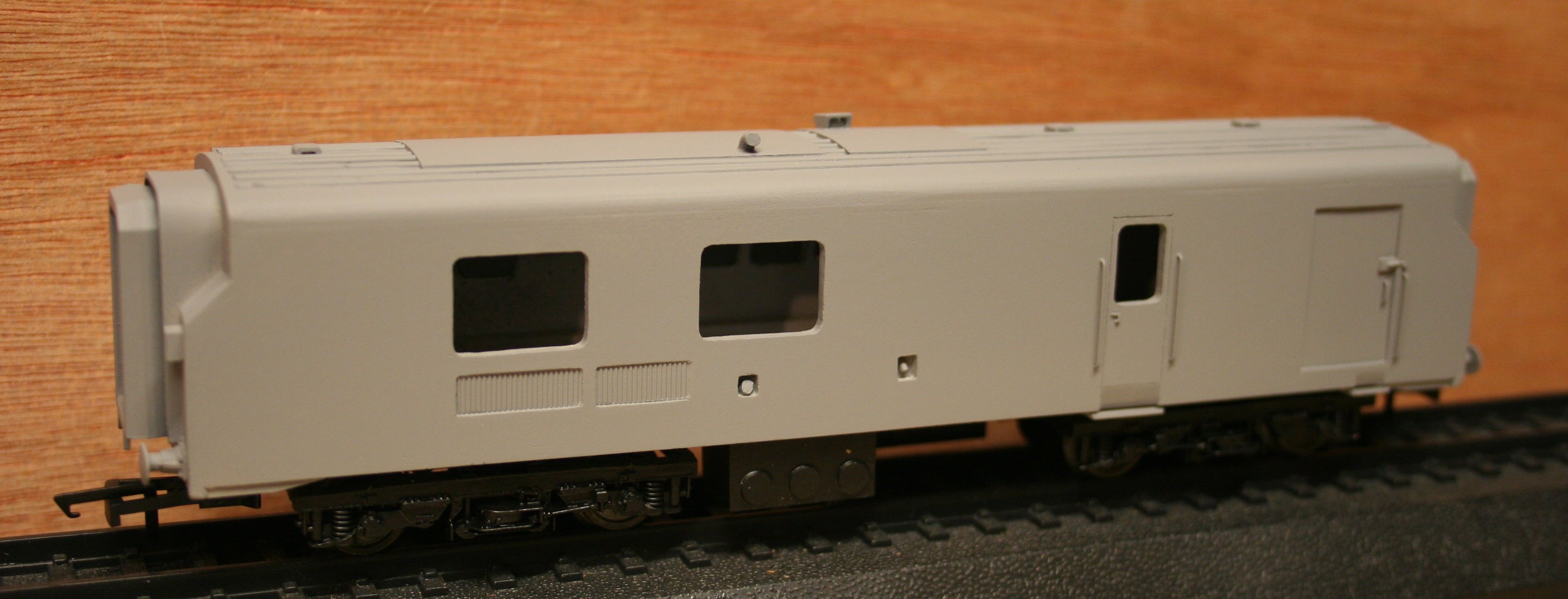
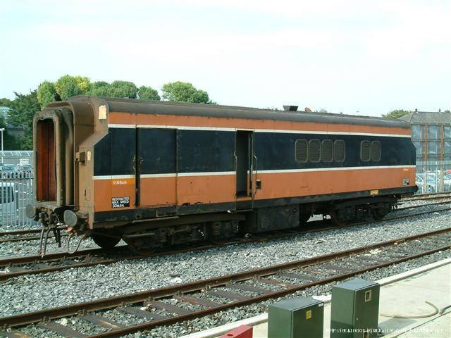
There are two issues with the buffers fitted to the IFM rebuilt Dutch van. Firstly, as has been pointed out, they are much too high. I think this is due to the buffer beam not protruding below the body lower edge. The second issue is that the buffers as seen in the picture are of a totally incorrect type. They should be of the retractable type, so that when coupled to Mk2 coaches with buckeye couplings, they can be retracted as the Pullman type gangway does the buffing. When coupled to a locomotive, the buffers are extended as so far as I know, no Irish locomotives are fitted with buckeye couplings. The only exception to this were the NIR Hunslets which were fitted with buckeye couplings and buffing plates from new. For my scratchbuilt rebuilt Dutch van, I used MJT 2934 BR Mk1 Coach Retracted Buffers. As can be seen from the following picture, they are a totally different profile to the IFM buffers. The second picture shows the real thing. Note also the extension of the chassis below the bodyline at each end, for the lower buffer beam. This appears to be missing on the IFM model.

-
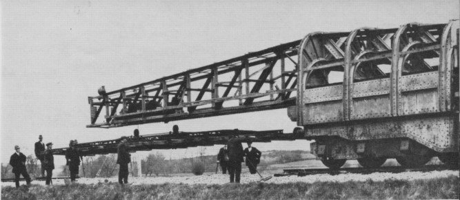
Here is a picture of the Bretland track-laying machine at work.
-
Larne Harbour had the only upper quadrant signals in Ireland. These were installed in 1933 by the LMSNCC when the station was remodelled. The GNR used unpainted round 'telegraph pole' type posts for many of it's signals.
-
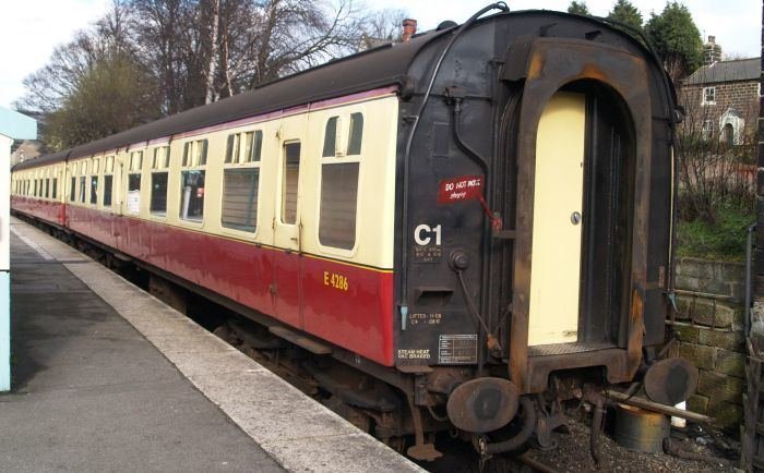
Back in the days of yore, before electric carriage lighting, and carriages were lit by oil lamps, steps and handrails were provided on at least one end of the coach for access to the roof in order to maintain the compartment lamps. After the introduction of toilets in coaches, access to the roof was required for the purpose of refilling the water tanks which were located above the ceiling. More modern coaching stock utilized the handrail as a water filler pipe which could be connected to a water hose at ground level, thus eliminating the need for day to day access to the roof. Indeed, if you look at the end of a BR Mk 1 coach near to a toilet, you can see what appears to be handrails on both sides of the end, but steps on only one side. This is because the water tanks can be refilled from either side of the track, using the "handrail" on that side. Many BR Mk 1 coaches have had some, or even all of the end steps removed as access to the roof is no longer required on a day to day basis. The following picture shows a Mk 1 end with "handrail" filler pipes on both sides, but only the LH side has, or had, footsteps, most of which have been removed.
-
I remember Limavady Junction was always a very busy station in the 1960s, with many RAF personnel from the nearby RAF station at Ballykelly coming and going. Whilst the RAF camp was only a short distance as the crow flies from the station, it was quite a lengthy journey by road on a UTA bus to get to the camp. It was not unknown for RAF personnel to persuade the train crew to stop the train on the airfield itself to drop them off. The railway crossed the airfield, and the main runway which had been extended across the railway during WW2. Trains had priority except in an emergency.
-
For those of you who may not know, NIR's third picture is of the remains of the footbridge and up platform at the closed Limavady Junction station.
- 91 replies
-
- 2
-

-
- 1975
- mixed livery
- (and 8 more)
-
The driver's position in most of the MPDs also contained a guards compartment which meant that the guard could hand the token directly to the driver immediately after the exchange. Presumably if a railcar without a guards compartment was leading the set, the exchange would be done in a different railcar, and the driver advised of the exchange by 'bell communication. I once had a cab ride on an MPD from Derry to Belfast, and witnessed first hand the exchange of tokens at speed. Most of the MPDs had sliding doors to the guards/drivers compartment, which did not have to be opened for token exchange. There was a small hatch in the door through which the exchange apparatus was rotated for the exchange. The noise of the exchange was something else. It was like a gun being fired. I also witnessed a Jeep failing to pick up the token at speed, and having to do a very rapid stop for the fireman to run back to collect the token. The GNR did not use tablet tokens on the likes of the Derry Road, but used train staffs which were more difficult to exchange on the move and required a net type apparatus. As far as I am aware GNR railcars were not fitted with exchange apparatus, and only steam locos regularly used on the Derry Road were fitted with the nets.
-
Zooming in to the picture of 122 above, there is a noticeable angle between the snatcher head and the supporting arm. This would mean that when in the extended position the arm would be at a downward angle so that the snatcher would be horizontal for the pickup. Basic geometry would mean that the snatcher would be at the same height as the lineside equipment, even though it was mounted higher on the loco than the original snatcher.
-
Just had a look through Derek Young's book 'The UTA in Colour', and there are a number of colour photos of service trains with unlined green coaches in the formation.
-
Had a look at Dundalk on Google Earth, the bay is exactly as the plan shown earlier, ie. a facing connection.
-
JHB, spotted a couple of errors in your otherwise excellent timeline chart. One of these is a layout error, where the 'Notes' for the 70 Class railcars have found themselves in line with the 80 Class, thus giving the impression that 80 Class centre cars were built using old NCC coaches. Another error is where it states that the BCDR diesel 28 is of Bo-Bo wheel arrangement. It was, in fact, a 1A-A1 wheel arrangement, as there was only one traction motor on each bogie driving a single axle.
-
Purchased my seventh China made Princess Coronation at the recent Modelrail Scotland in Glasgow. Superb model, finely detailed, 5 pole loco mounted motor, electrical pickup from all driving wheels and all tender wheels, and DCC ready. Each one of my seven locos is physically different, as were the prototype locos the models represent. Now that is attention to detail.
-
The 70 Class power car bogies certainly bear a resemblance to the B5 bogie in some respects. The B5, with modifications, would probably make a passable representation in the absence of anything better for a model of a 70 Class.
-
The MED and MPD railcars are a very mixed bunch. Some MEDs and all the MPDs and their trailer cars were converted from existing coaches of LMSNCC origin. Other MEDs and trailers were built new to a UTA design. Bogies were basically LMS type with roller bearings. 70 Class power cars were built new to a design similar to LMSNCC coaches, but the trailer cars were converted from UTA and GNR coaches. Bogies on the trailer cars were, like the MEDs and MPDs, basically LMS type with roller bearings. Bogies on the power cars were of a UTA design, and there is nothing similar as far as I am aware. The 80 Class railcars and trailers were built to the BR Mk2b design, with one or two trailers converted from loco hauled MK2c coaches to replace vehicles damaged by terrorist activity. Bogies on the trailers were B4 type, but on the power cars the bogies used were similar to those on the BR Class 73 locos. The 450 (Castle) class railcars and trailers were built to a Mk3 design, mounted on ex BR Mk1 underframes. The bogies used were the same as for the 80 Class, with B4s on the trailers, and on the power cars bogies that were similar to the BR class 73 locos were used.
-
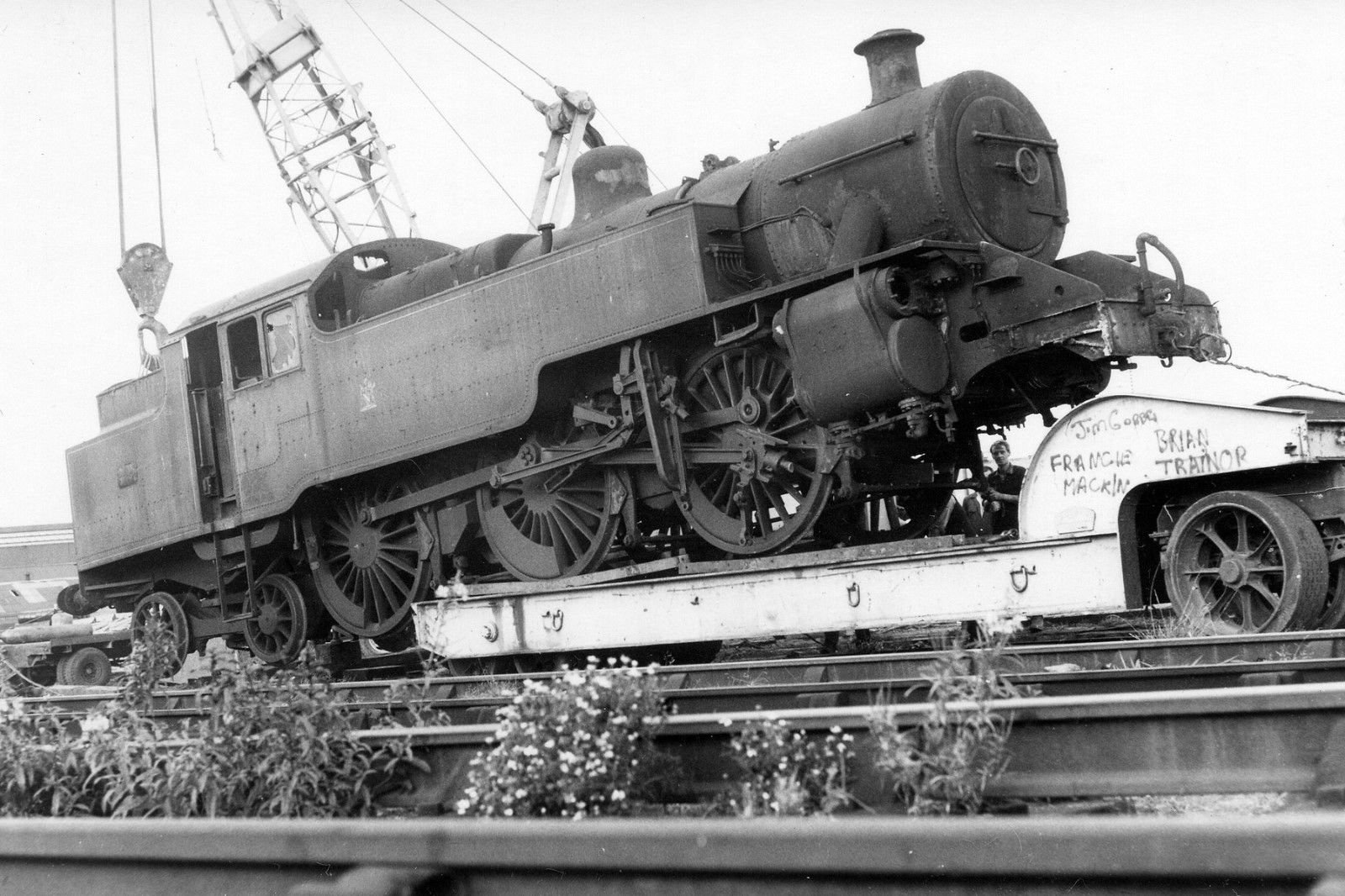
Ignominious end for a Jeep. Picture for sale on eBay. https://www.ebay.co.uk/itm/RailPic-Ulster-Railways-2-6-4T-being-hauled-away-by-road-for-scrap/372566557893?
-
Some fifteen years ago while building a new club layout which was to be an accurate representation of a local junction station in the heart of Scottish Malt Whisky Country, namely Craigellachie, we found that there was no ready made backscene suitable for the location. It was impossible to get any photographs of the real thing, as the old station lay deep in Glenfiddich, which has steep wooded slopes on both sides, and the camera could not get far enough away to take any worthwhile shots. A compromise had to be made, and it was found that a few miles up the line in the Glen of Rothes, the landscape opened out enough to get a series of pictures across the Glen. Ideally, there should have been more wooded coverage, but it was the only vaguely suitable location that could be found in the time available. If I was going to do it again, I would pick a day when the light was better, and not on a dreich day in the middle of January. Pictures were duly taken and edited. They were then spliced together as can be seen in the following picture. After much adjustment to ensure the pictures matched up in colour and brightness, the finished picture was printed off on A3 sheets. The picture was also printed off in reverse, so that the backscene could be extended without it being too obvious. The pictures that contained the bungalow and distillery were only used once. There are six pictures spliced together, the join in the middle can hardly be seen, even at this stage. Incidently, the distillery is right next to the old trackbed, which then curved deep in the valley in front of the camera, and went off scene between the green field and the woods to the left in the picture.
-
You could try these wheels. I have used them on MM Cravens coaches. https://www.petersspares.com/hornby-h51-replacement-wheel-set-for-lima-ooho-coach-stock-x9695.ir
-
The Lima 201 bogies are 48mm wheelbase compared with the MM 201, which are 49mm. The centre axlebox on the Lima is off centre towards the front as it should be, but the motor unit centre axle is central, and does not line up exactly with the axlebox, but it is not too noticable. However, on the assumption that the MM bogie is the correct length, the 1mm discrepancy between the two makes is not worth worrying about. A wheel swop on the Lima 201 is perfectly feasible. I once had a large fleet of Lima BR locos, all of which had had their 'Pizza Cutter' wheels replaced with Romford wheels. Extra pickups were fitted to all wheels, and extra weight added to compensate for lack of traction tyres. With one or two exceptions, all my Lima BR locos have since been rechassised with either Bachmann or ViTrains chassis
-
I too have the UFTM list of drawings, obtained many years ago. Since then I have obtained many of the drawings by contacting Mark Kennedy at the UFTM, and he kindly supplied the drawings required for a small remuneration per drawing. I also managed to arrange a visit to the UFTM archives, where I was able to search through the drawings collection, and obtain copies of drawings that were not on the list.
-
Video Website Updates
Dhu Varren replied to irishrail123's topic in Photos & Videos of the Prototype
The last vehicle in the train is a Brake Generator coach. -
It's not an A Class. Its a Maybach engined C Class.
-
When drilling holes for handrails, I always mark the exact location for the hole with a sharp point, like a needle, or the point of a compass. When 100% satisfied with the position of the hole, then make a indentation with the sharp point. This then acts as a pilot hole for the fine drill required for drilling the hole, and ensures it drills in the exact spot..
-
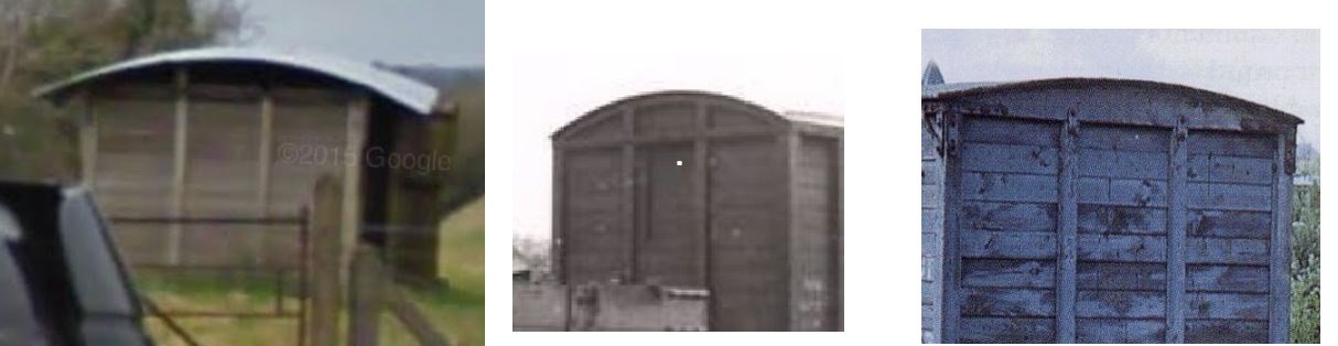
I have not seen this van in the flesh, just close up pics taken off the Google image. However, the end framing is more akin to the NCC than the GNR. The images below show the differences quite clearly. The first image is a snip from the Google image, and clearly shows that the two centre vertical frames continue past the horizontal frame at the top. The centre picture shows an NCC van end, which has the same frame arrangement on the end. The third picture is of a standard GNR van end, which clearly shows the difference between NCC and GNR van end framing.
-
Close up inspection of the external framing would suggest that it could be an NCC van, rather than a GNR van.