Dhu Varren
-
Posts
547 -
Joined
-
Last visited
-
Days Won
1
Content Type
Profiles
Forums
Events
Gallery
Blogs
Everything posted by Dhu Varren
-
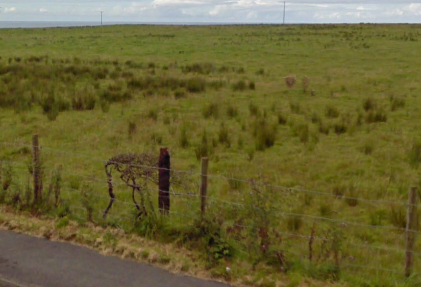
There are still quite a number of stumps of the old overhead line poles to be found by the roadside between Portrush and Bushmills, particularly between the Junction of the Ballintrae Road and Bushmills, which is where the photo was taken. The overhead line poles suffered badly from corrosion due to their close proximity to the sea, and when new poles were needed, to keep costs down, the original poles had reinforcing steel rods inserted, and then were filled with concrete.

-
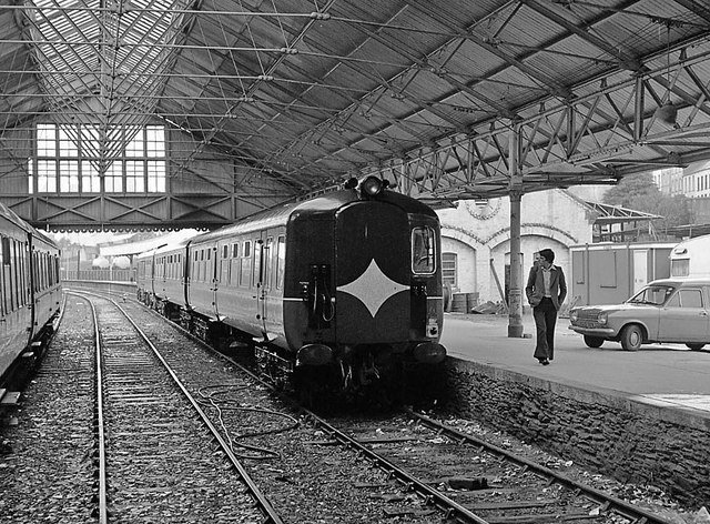
The second picture is of Sir Henry in the bay platform
-

Diamond Crossing Protector
Dhu Varren replied to Paddy Mac Namara's question in DCC, Electrics and Electronics
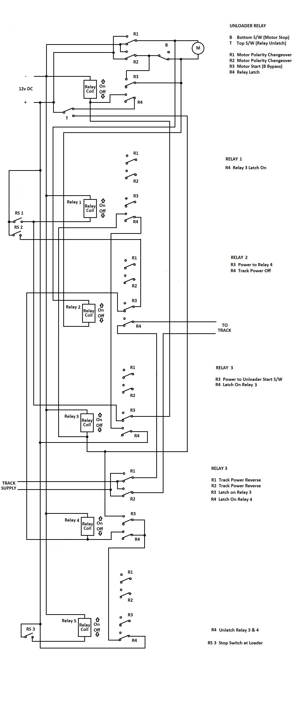
The detection circuit was built to automatically detect and unload a narrow gauge train of 4 side tipping hoppers loaded with fine ballast. It was for a Club layout, and because of that, the circuit had to be as simple as possible, hence the use of relays and no electronics. However, despite rigorous testing and operating flawlessly, on it's first outing it failed miserably with spectacular smoke effects. I am told that, because I was unable to attend that exhibition. The post mortem revealed that the builder of the layout had decided to tidy up the wiring under the layout, and had got his wires mixed up with the wiring supplying the unloader. Once the fault was found and rectified, the unloader worked fine once again. Below is a description of how the circuit works, and also the circuit diagram for it. All four hoppers are fitted with magnets. There are two reed switches at the unloader, the first positioned such that each hopper will stop in the correct position for unloading. The second is activated by hopper 1, so that the track power is reversed ready for the return to the loader once hopper 4 has been emptied. The unloader has an arm attached to a crank fitted to a motor. When activated, the arm extends and pushes the side hopper body over, thus tipping out the load. On reversing back into the quarry for reloading, a fixed trackside arm returns the hopper bodies into the horizontal position ready for loading. Loading is done manually. A push button held down till the loaded train clears the loader completely, starts the journey to the unloader. Hopper 1 arrives at RS1 and activates the unloader. Relay 1 switches on and is held on by the hopper magnet holding RS1 closed. Relay 2 switches on, powered by the unloader motor supply, and switches off power to the track. It also completes the circuit to Relay 4, which only activates when hopper 1 reaches RS2. When the unloader reaches the top, switch T switches off the unloader relay which reverses the unloader direction. Switch T also momentarily supplies power to Relay 3 which switches on and latches on via relay 1. When on, Relay 3 inhibits RS1 from activating the unloader circuit. When the unloader reaches the bottom, Switch B cuts power to the motor thus stopping the unloader, and releasing Relay 2, which restores track power. Hopper 1 moves away from RS1 thus releasing Relay 1 which unlatches Relay 3 restoring the RS1 function. Hopper 2 arrives at RS1 and the cycle repeats itself, as it also does for hoppers 3 & 4. As hopper 4 arrives at RS1, hopper 1 arrives at RS2. Relay 4 switches on via Relay 2 and latches on, reversing track power. It also latches on Relay 3 to inhibit RS1. The complete cycle repeats for hopper 4, except that Relay 3 stays latched on. On completion of the cycle, track power is restored, but in the reverse direction. The hopper leaves RS2 and passes RS1 without anything activating except Relay 1, which does nothing, as Relay 3 is already latched on via relay 4. On arrival at the loader, the hopper activates RS3 switching on Relay 5, which unlatches Relay 4 thus reversing the track power, and releasing Relay 3 ready for the next journey. With Relay 3 unlatched, RS3 does not activate Relay 5. Well, you asked for it, I hope that it all makes sense. The amazing thing is that it actually works.
-
Diamond Crossing Protector
Dhu Varren replied to Paddy Mac Namara's question in DCC, Electrics and Electronics
I recently built a detection circuit using reed switches and Neo magnets. I found, the same as you, that when the reed switches were installed parallel to the direction of motion of the magnet, as in your demo, the reed switch pulsed twice as the magnet passed. However, by installing the reed switch at 90 degrees to the direction of motion of the magnet (ie across the track), the double pulse did not happen, just a single one. -
Colin, you could try PRONI Historical Maps. I looked this morning and once I got the hang of it, managed to get a map of Derry showing both narrow gauge stations. The map can be zoomed into using the + & - buttons almost hidden in the top L/H corner. There is a measuring display in the bottom L/H corner which changes as the curser is moved over the map. My measurement of the platform was in the region of 70 metres taken on different maps.
-
DCC Sound for locos in 2020
Dhu Varren replied to mmie353's question in DCC, Electrics and Electronics
If you are into working with the Lokprogrammer, it is quite a simple matter to add Drive Hold, Coast and Brake functions to The ESU sound files for the 071 and 201. It is simply a matter of finding an FT fitted American loco with similar running characteristics to the 071 or 201, opening the program, opening sound slot 1, and deleting the contents completely. Any other unwanted sounds can also be deleted. Then open the 071 or 201 sound file alongside the now empty American loco program, and copy and paste the entire 071 or 201 sound slot 1 from the 071 or 201 program into the empty program, and Robert is your uncle. Then copy other sounds like horns etc and insert them where they need to go. All my 071/111s and 201s are running with downloaded ESU programs, but with Full Throttle features. It is worth trying, as you can always reprogram the decoder with the original ESU program if you are not happy with the results, or you screw up the transfer. -
I think your eyes are deceiving you airfixfan, the box is in exactly the same position in both photos and the 1951 plan shown earlier.
-
1937 picture of Victoria Road station clearly shows the signal box next to the river.
-
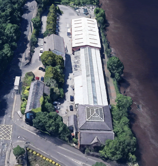
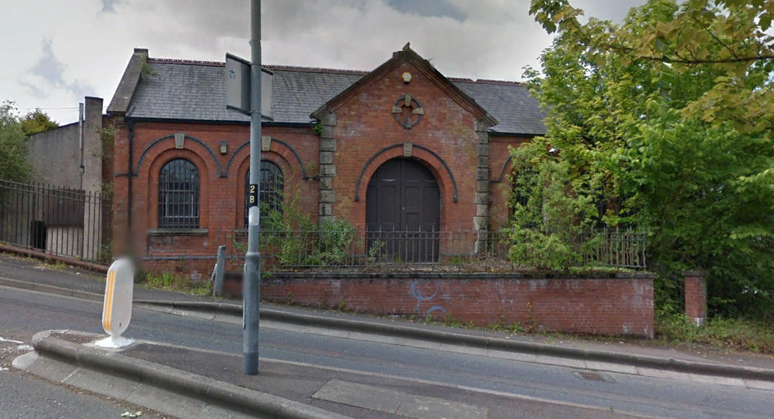
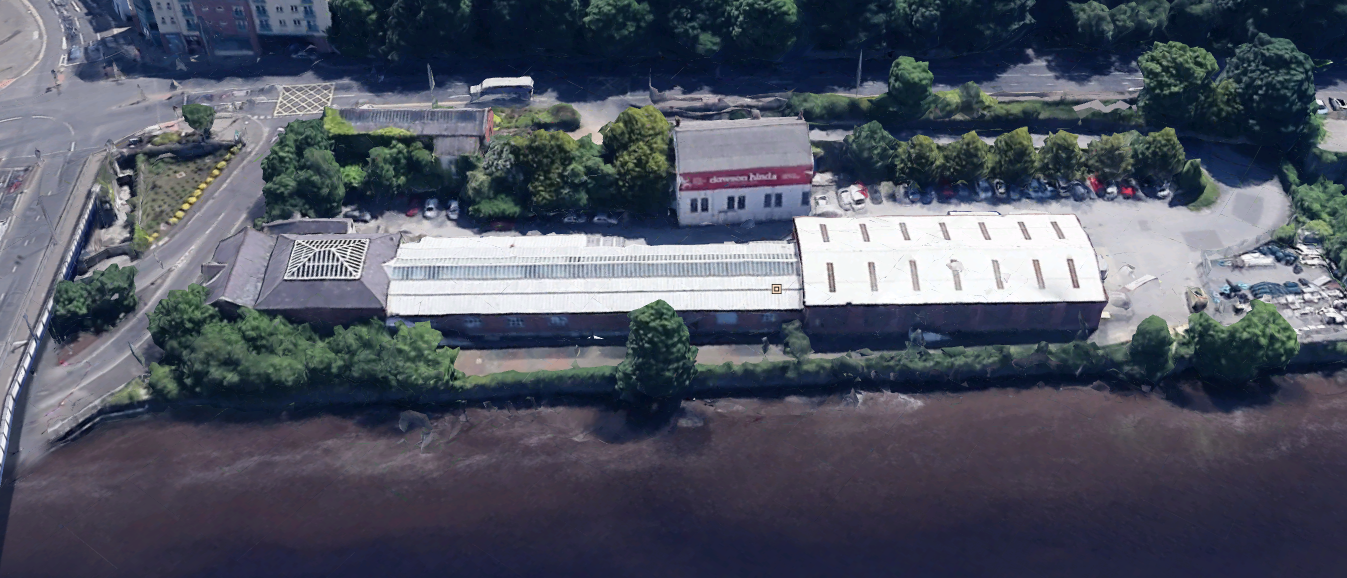
Some current pictures of Victoria Road station from Google Earth. Station frontage. The road has replaced the original road to the station, and is now one of the accesses to the lower deck of the bridge. Up till the mid 1960s the lower deck of the bridge carried rail traffic, both 5'3" and 3'0" (3'0" ceased on closure of the CDR) on dual gauge track with a wagon turntable at each end. Wagons were moved by rope and capstan, or by shunting tractor The lower deck was eventually converted for use by road traffic. The station from the air. The modern building at the top centre of the picture is a new extension added onto the original platform canopy which has been extended sideways to cover the old trackbeds, and then walled in as can be seen in picture 3. A side view of the station. The building above the station building is a new build. The city fire station occupied this site at the time of the railway closure. The road running left to right is Victoria Road.
-
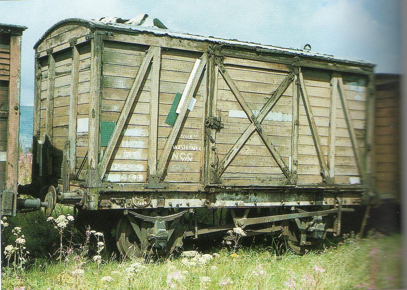
I discovered a drawing in a book, the name of which I can't recall, but I think it was a book of LMS goods vehicle drawings. I do have a copy of the drawing which was 13/3447 to diagram D2074 lot number 1326, running numbers 2401 - 2500. The vans were actually built by the LNER, which could explain the LMS plates, as the parent company, the LMS, probably ordered the vans on behalf of the NCC.
-
LMS 2493 was one of 100 built for the NCC, by the LMS, to replace vans destroyed in the Blitz. Here is number 2489 from the same batch. Note the LMS plate above the L/H wheel.
-
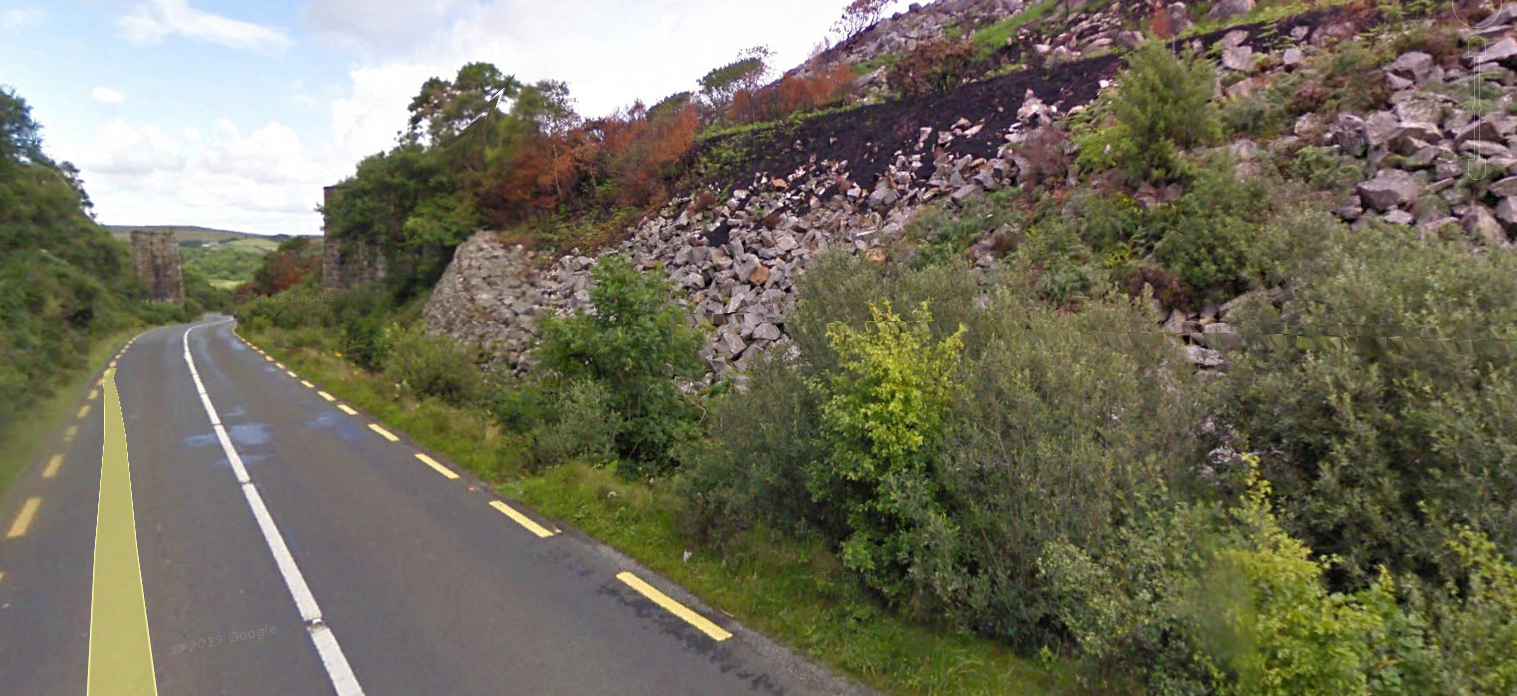
A current view of the bridge over the N56 in photo 3 looking North taken from the road below where the train is. The train is heading towards Letterkenny having traversed the infamous Owencarrow viaduct a few minutes earlier. Not much has changed except that the bridge steelwork and the two central pillars have been removed. The yellow line on the road is from the Google Earth image.
-
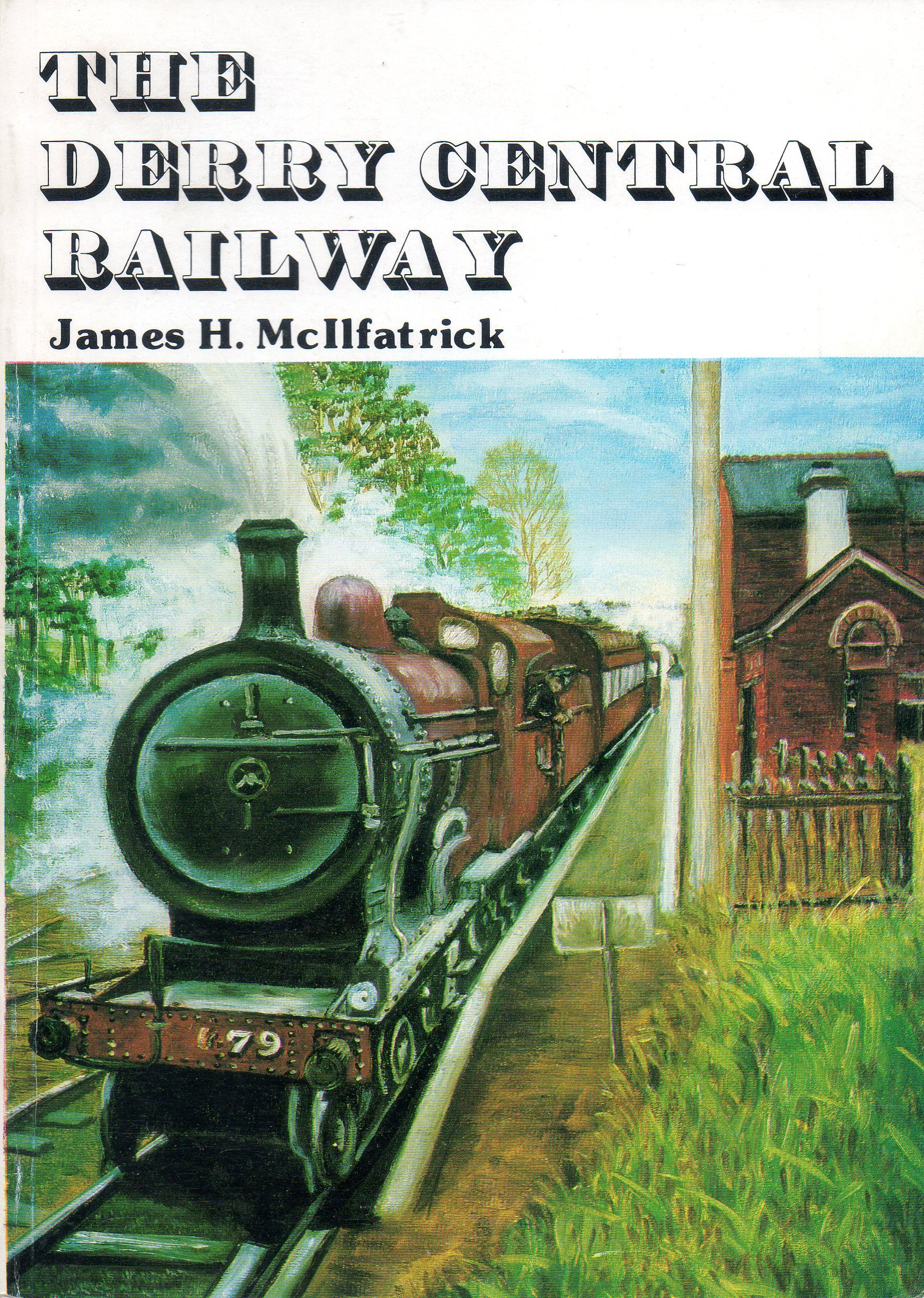
There is a locally produced book on the Derry Central published 1987, paperback, 132 pages with many photographs.
-
Peculiar CIE Rolling Stock
Dhu Varren replied to DiveController's topic in Photos & Videos of the Prototype
I would agree with Mayner. The third vehicle is most likely an ex LMSNCC van. It has the classic NCC outside W irons. -
The shunter looks like the old Triang/Hornby 4 wheel Dock Authority shunter, with added white bits to represent CIE livery.
-
Twenty or so years ago I decided to build a model of the NIR Railbus. As the real railbus was built using Leyland National bus parts, I purchased two Tower Models Leyland National bus kits, one red London Transport, one green London Country. I looked closely at the bus kits, and decided that there were not enough windows of the right size to build the railbus, so the project was shelved, and the kits consigned to the junk box. More recently, while having a sort out, I came across the unbuilt kits, now robbed of parts for other road vehicles, and decided it was time to dispose of them. However, it suddenly came to me that the BREL Pacer was a development of the railbus, and it too used Leyland National bus parts. A quick check revealed that the Hornby Pacer had windows of the correct size, but it would require two bodies to give the correct number of windows for the railbus. Two bodies were obtained and examined. Sure enough, with a bit of cut and shut, the two sides could be produced for the railbus. However, the roof profile was totally incorrect, and was too wide. It was decided to make up the sides only from the Pacer bodies, and use the roofs from the bus kits, suitably shortened and spliced together, plus the two front ends. Apart from the doors, the Pacer sides were not deep enough, so plastic strip was used to extend the depth of the sides. All the parts were assembled, but the bus roof heating units were not correct for the railbus. The Pacer one was, so one unit was removed from a Pacer roof, and fitted to the railbus. It was also discovered that the Pacer doors were not the correct pattern for the railbus, so the Pacer doors were removed, and those from the kits were spliced in instead. The pictures show the origins of parts. Red or green parts are from the bus kits, orange or brown are from the Pacer bodies, and white is additional plastic, except for the white line above the windows which was part of the Pacer livery. The Pacer underframe was totally unsuitable for the railbus, except for the axleboxes, so these were cut out, and along with black plasticard, and white plastic strip, used to build the railbus underframe. Motorising was the most difficult bit, as I did not want anything protruding into the passenger compartment, so everything had to fit below the floor. Four different transmission systems were tried, driving one axle, and eventually one was found that was not too fast, slow or noisy. A small Mashima motor and flywheel powers the railbus. Hornby Deltic wheels were used with a three point suspension system to ensure the best possible contact with the rails. The Deltic wheels were used as they are plated and stay clean longer, they also have a wider tyre which makes for smoother running through point frogs, and the flange is slightly coarser than Jackson Romford wheels which helps such a long wheelbase vehicle negotiate sharp curves. A sound decoder has been fitted, again below the floor, but the speaker is fitted inside the roof. Connection to the decoder is by phosphor bronze strip fitted to the inside of a window pillar on each side. It is thin enough and narrow enough to allow the glazing units to be fitted over it, so no wires within the passenger compartment. Thin wires connect the top of the strips to the speaker, and the decoder is attached to the bottom. The sound is generic, having been taken from the ESU website and modified to be acceptable in conjunction with video footage taken of the railbus on the DCDR, in other words, sounds like a bus. Holes have been made in the railbus ends for red tail lights and white headlights, still to be fitted. The interior is made up using plasticard and the seats from the bus kits. All during the construction and testing, something bugged me about the ends of the railbus, but I could not figure out what it was. Only when it came to painting did I realise what it was. There were two versions of the Leyland National bus, the Mk1 and the Mk2. They both had similar, but different front ends, and the railbus used the Mk2 front. My bus kits were Mk1. I don’t know if Tower Models ever produced a Mk2 bus kit, but I certainly was not going to undo the work already done. Painting was done using my concoction for NIR light grey all over, and then after masking, my concoction of NIR light blue, followed by the orange panel, all sprayed. The black on the ends was masked and brush painted. Decals were made up on a PC and printed on to clear decal paper. To finish the railbus, glazing and lights need to be fitted, and the underframe completed.
- 10 replies
-
- 17
-

-

-

-
There is footage of Hunslets 101 and 102 double heading a fert working at Derry and Coleraine in 1988 on Markle Video 'Northern Ireland Railways Archive Volume 2'.
-
That crane is not the one in question. That one is LMSNCC number 3076, which incidently is almost a dead ringer for the old Triang Hornby model. The GNR crane at Whitehead is the following, which is a close match for the Oxford model. https://hiveminer.com/Tags/gnri%2Cwhitehead
-
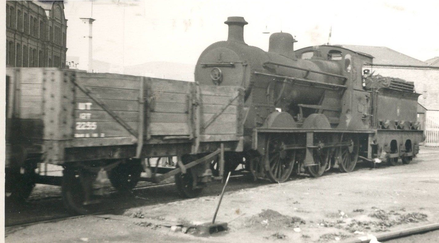
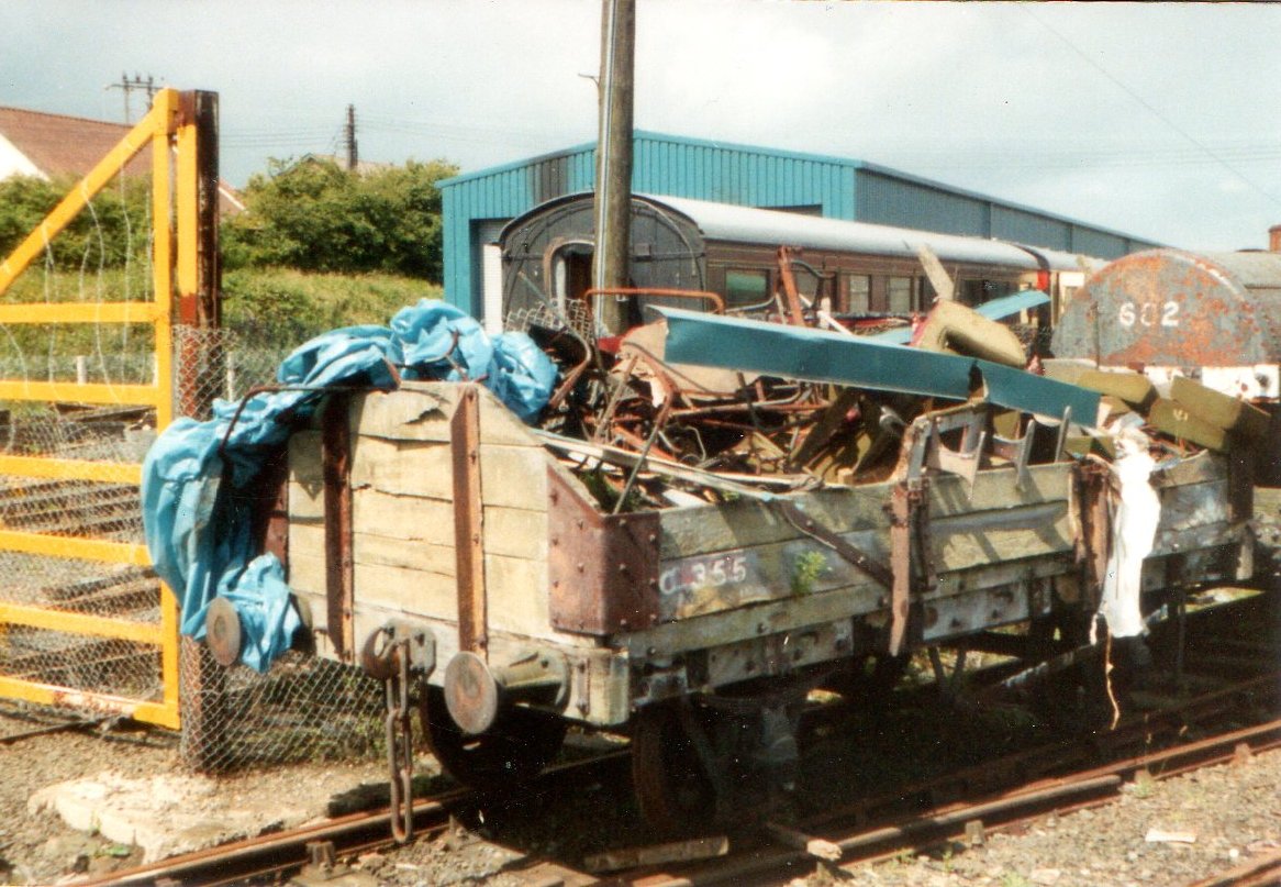
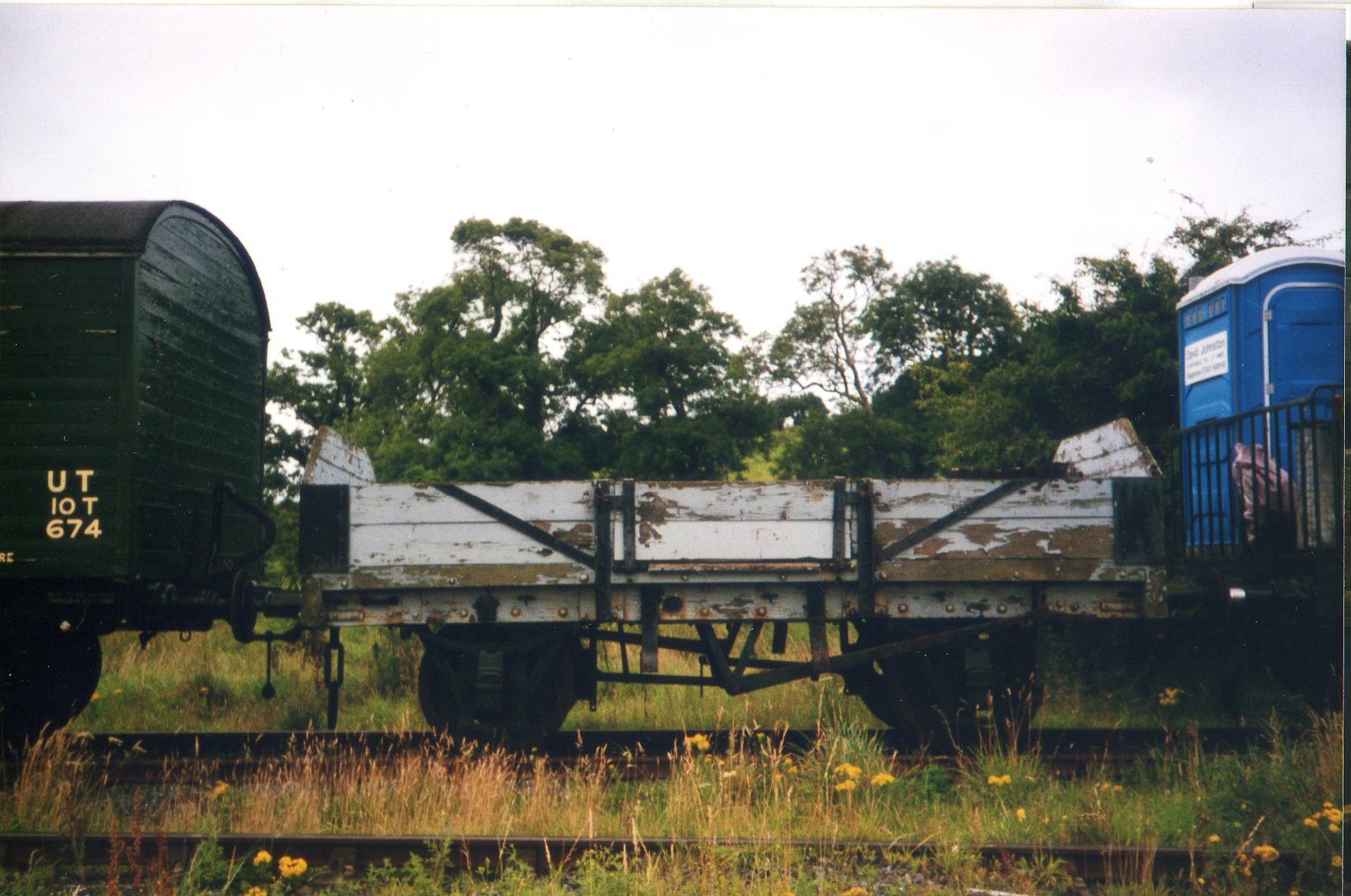
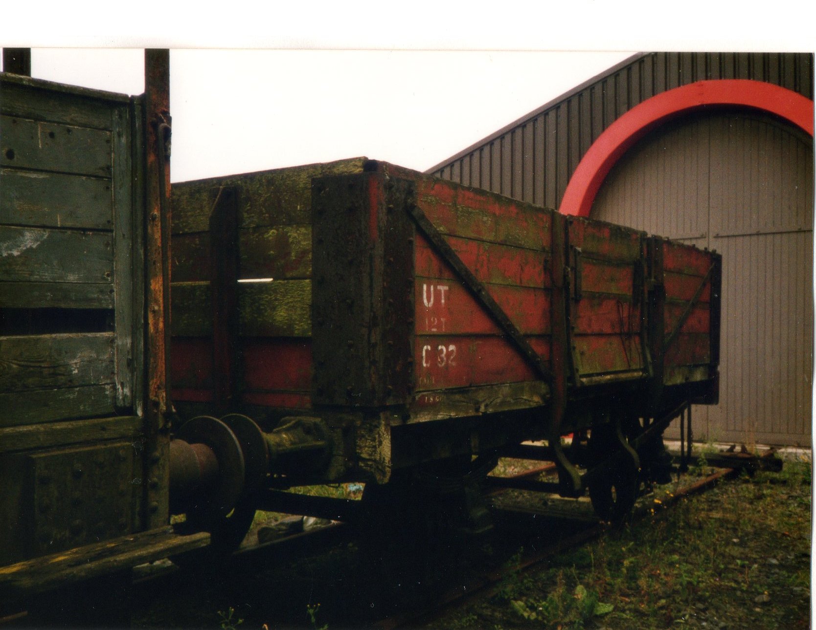
The four plank wagon seems to have been the most numerous type in service, and I can't say that I have seen a 'cut down' version of a 5 plank wagon. Here is a picture of a 12T 5 plank wagon. Probably from the 1941 built batch. Pictures of 'cut down' wagons at Whitehead and Downpatrick. Picture of 4 plank wagon C32 at Downpatrick.
-
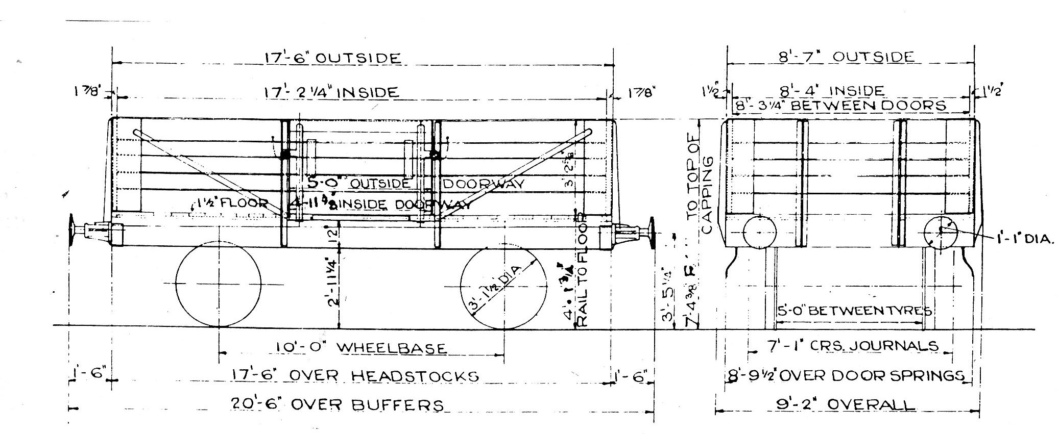
Here is a drawing for an NCC 12T open wagon built about 1942 by the LNER to replace air raid damaged stock. 150 were built.
-
There were twenty seven kits purchased in total. The first 20 built had the same size driving wheels as the Southern Railway N Class, namely 5ft 6in, and were designated Class K1. The next six built had 6ft 0in driving wheels, and were designated Class K1a. One kit was never built and was retained as a spare.
-
This is a Yorkshire Engine Company locomotive, works number YE2481 used by British Steel. If you look closely, next to the cab window is the number BSC 1. The first picture in this thread is of BSC 2 which is works number YE2480. This picture found on the internet when searching for the Yorkshire Engine Company.
-
Will be there on stand C31 with Drumslochtock Summit. If you have time, do drop by and ask for DJ.
-
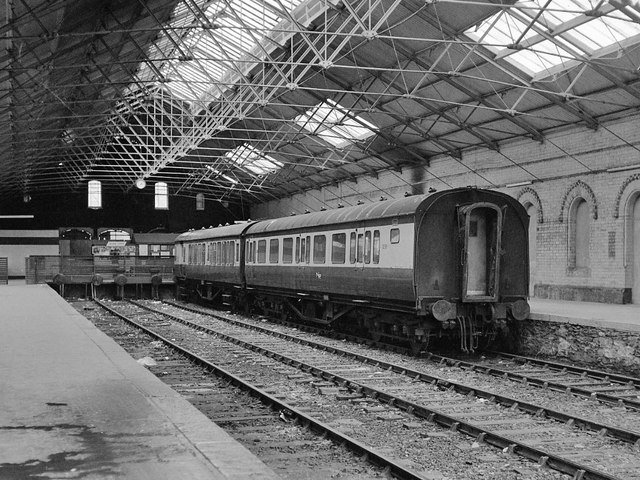
It certainly is the original roof JHB. See pictures below. The building to the right of the 80 Class is the rear of the two road engine shed, which was alongside the platform. There was always at least one open door from the platform which allowed a look inside the shed from the safety of the platform. Strabane and Omagh would not have been familiar to the 071 class, as they did not make an appearance until more than ten years after the closure of the Derry Road.
-
It is worth trying to sell them, you would probably be surprised. I recently sold on fleabay an Airfix 1/32 Bond Bug Car kit, loose in a plastic bay, without decals and with a photocopy of the assembly instructions, but all parts were present. The kit sold for £118, having started at £10. At one point, before I had identified what it was, I had considered chucking it in the bin.