Junctionmad
-
Posts
1,136 -
Joined
-
Last visited
-
Days Won
1
Content Type
Profiles
Forums
Events
Gallery
Blogs
Everything posted by Junctionmad
-
brassmasters and others do make etched brass components that can be made into scale ( or near scale ) working rodding. this article might be useful reading , http://www.clag.org.uk/green09.html its not for the faint hearted
-
and of course thats O gauge , !!!
-
yes but it doesn't suit ballasted track , it relies on being able to lift out the section of track . I suppose you could arrange for the whole track and ballast and everything to be removed, maybe ?
-
well yes, but normally with track like PECO , you do an initial install, temporary pin it etc and test it, you can then mark the rail locations and lift/move the track. Then on the final install , soldered up , ballast paint etc Again , I'd lay it continuous across the baseboard edge , soldier up to the screws and cut with a dremel
-
Im not a fan of the isolated copper clad sleeper approach ( I must say I like RichL idea). But I offer my experience from many years ago, on my 2nd layout , when I built all the plain track from copper clad, and used the method at baseboard joints ( and my club uses the same idea still today ) . Personally , I found if you catch the end of the rail , in my case it was a lifting section that got caught in a coat as it was coming down, the copper clad sleeper will not protect the track , either the copper layer fails or the sleeper breaks away. So in reality i dont think its a particularly robust method at all. (and in plastic track its not great visually ) . Its marginally stronger then the plastic sleeper , but its all still quite fragile to repair that section , i used small brass screws that were screwed into predrilled holes, the tops cut off and soldered to the bottom of the rail ( and optionally replacing a dummy sleeper ) . Done carefully this is near invisible when painted , I have seen some where the screw head was left , but it creates a very visually intrusive " blob". The damage trashed nearly 2 feet of copper clad track, that had to be relaid , ( it was disrupted to the next rail joint ) and a large hole in the coat , rail edge is sharp !. so I personally think you need something anchored deeper in the baseboard , then just a glue joint over a sleeper length just my tuppence
-
Just be aware that the problem is only in the TCS decoder M4 ( which i think has been superseded anyway ). Mysteriously , the same bug appears in the LaisDCC decoder, no explanation advanced . There are a few different other far east decoders around as well
-
There have been a few attempts at near scale working point rodding , notably amongst P4 enthusiasts, ( if you have access to their Forum, there is a useful debate ) . Personally , its way to finicky to get both operational and scale aspects of it right. dummy rodding on top, working wire in tube or rod operation below in my view dave
-
I did some tests before christmas in prep for my own track laying. I personally dont see the advantage of cork, other then to create a ballast shoulder , and that isn't relevant inside a station area. I tried a small area of 4mm approx UV stabilised close cell PU foam, rather like stuff used in camping carry mats. while it seemed better , my only concern was it " dented " easy and didnt quite return when the pressure was removed, Im not sure about any conclusions, my tests was hasty and over about 5 feet of code 75 DCC concepts track . I dont know if a rigid stable surface, the plywood track top , is better then some " cushion" or worse The cork does nothing if its ballasted with PVA as the whole thing looses any cushion effect . I know this from the previous layout i built many years ago . Apart from creating a ballast shoulder that is . dave
-
more to do with teh number of maintenace and platelayers that were around, and doing maintenance ane teh greater level and traffic that existed. We forgot how many men were employed at ledger stations, Claremorris at one time had , 12 porters, multiple drivers, good yards operatives, shunters , etc etc in excess of 30 people were directly employed , today there is two !
-
Two seperate issues are flagged here One is " loudness " , getting a good loud sound from a loco is a function of speaker size and speaker output power , loudness has a logarithmic square law relationship , ie 2x loudness requires 4 times the power , 4x loudness requires 100 times the power. Hence the speaker and current requirements for significantly greater loudness are considerable. The second is the " simulation " of the both the Doppler effect and scaling up the decrease in volume to better represent a loco at a distance even though in scale terms , on most layouts the loco isn't far away at all! Technically this could easily be done in the loco sound chip , BUT, the loco then needs to know where it is on the layout. ( or rather the dcc controller needs to be location aware ) For example , Using a combination of Railcom and section occupancy detection, it is entirely possible with current dcc systems to enable a dcc controller to issue location specific commands to a particular locos sound chip. Such commands could for example * decrease volume as the loco moves away from the main layout viewing position * simulate Doppler by playing sounds with rising and falling frequencies * cut sounds , when the loco leaves the scenic area , or enters tunnels etc Other effects could be signalled as well * auto dimming main loco lights on entering station limits * auto triggering flange squeal at suitable curves etc The main impediment , besides money , is its all reasonably complex to make hang together and it's likely only a few modellers will either understand it or be bothered enough to try. At Warley , the Belgium layout , used a combination of dcc loco sound and " layout " sound , things like proper automated station announcements etc. It was very realistic
-
It what's happens in state bodies when you seperate capital requisition from operating revenue accounting . In essence , there is no requirement to minimise capital expenditure as in effect all capital spend is political and provided above and beyond the companies normal financing. Hence the lack of concern over " revenue " service life. The stock wasn't bought out of operating revenue and can be discarded when a new capital spend is made available. Unlike a proper commercial company , where the euros all come from the same place whether it's cspitsl or operating spend Hence the " lower cost " arguments which relate solely to operating revenue. Where IR to raise the purchase price commercially , then by gum, service life would be top priority , aka you sweat assets , that's how you achieve " cost " efficiencies What's strange is the lack of comtingency planing , IR is now faced with rising passenger numbers again. Yet the governments fiscal space is very limited , which suggests that further significant rolling stock investment will be very difficult in the next few years. Destroying assets that arguably have considerable service life is a very stupid thing in the face of capital restrictions. The nature of the icr , is that it cannot be easily reconfigured and IR has no second tier assets Interesting despite all these promised " cost savings " , none of which are actually audited , IR losses climbed in 2007 , 2008 , despite railcar " efficiency " Partially , this is because many of IRs so called savings , are merely inter-departmental, often simply transferring savings in one department into costs in another , mainly because staff costs cannot be actually eliminated
-
my own are on the CAD as we speak ( and I must acknowledge a fellow MERG member for his contribution ) , They are 4mm and 6mm laser but grid system , that supports the track board ( 6mm ply 0 all ply is european Birch , with interior grade glue. ( laser cuttable )
-
whatever the effect on full size railways here, It will be a right pain for us railway modellers, VAT at point of import again, and given the postie doesnt take money anymore, double plus pain and mega difficulties for things like Parcel Motel
-
silicon tubing and suitable wire , available from eileens emporium
-
Irish freight yards and sidings. Prototypical operation and detailing.
Junctionmad replied to dave182's question in Questions & Answers
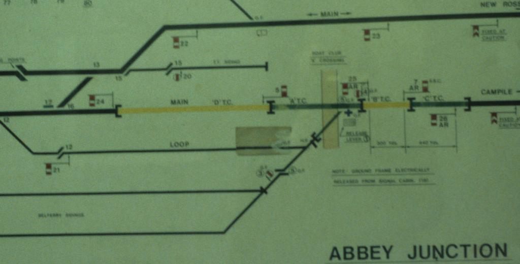
Heres the aforementioned Bell Lines yard access signal diagram , snippet This was a very busy yard so it warranted considerable signalling First thing to notice is the yard is " inside " the Home signal #26 , ( all irish single lines had the distant fixed at caution ) hence the ground frame could be simply released electrically as the train did not need to access the Block to Campile Several Track circuits existed to inform the signalman, and to enforce locking , as the cabin had no little direct sight of the yard. ( Abbey junction was originally set up to control the junction with the New ross line, and the plethora of signalling reflects that . The ground frame , controlled ground disk ( 3) and trap point (5) , Shunt signal (4) on a dolly off the inner home #25 the entrance point(2) to the yard at the east end of the loop, and (1) a release lever, I cant see a (2) so maybe that lever was a spare . SO its a 5 lever ground frame marked at portion "+". The east exit from the loop was controlled directly from the box via signal #21 and associated trap point. ( all lines exiting onto passenger lines would have trap points ). Disk (4) acted in ireland as a " shunt signal " , as opposed to say the ringed signal seen on GWR lines. It was typically mounted up on an associated main signal signals #5 and #7 are " starters " by the way SO this busy yard , had an exit signal #21 controlled directly from the abby J Cabin, and an alternative exit/entrance controlled by the shunt disc. (4). IN the typical operation as I remember it , the loop stored empty flats and was also used to allow the engine to run around completed liners normally empties would draw forward of the shunt disc, (4) ,the frame released ( a bell signal push button on the frame ) , point (3) thrown, trap point (5) set correct then finally the disc(4) pulled off and the train reversed into the yard . Note the internal point is operated manually as you say. there was no exit signal on the east exit, primarly because the ground frame operator was in visual sight of the driver and the frame could only be released if was safe to exit. signal #21 was controlled directly by the box, firstly because the ground frame was too far away and out of sight and secondly because the loop was used to store trains out of the way of approaching campile /rosslare traffic and released out onto the passenger line when safe by the Abbey Cabin. As an aside note that the track west of abbey to waterford central was double track , controlled by Absolute block, the last at the time in the country. Hence traffic from New ross, crossed over to the south line ( i.e. nearest the box), as they was a gradient up to new ross here, the spring points ( in effect a catch point as opposed to a trap point ) , this was to ensure anything running back , would not end up on the wrong line , Abbey cabin , is just west of point#12 at the extreme left of the picture snippet Note that in waterford it was always called BellFerry ( the areas around is known as FerryBank) SO heres an example where a degree of signalling was required as it was a busy place, and out of sight of the signalman etc dave copyright Llangollen Signalman
-
Irish freight yards and sidings. Prototypical operation and detailing.
Junctionmad replied to dave182's question in Questions & Answers
yes absolutely , CIE was parsimonious !!, entrance and exit signalling for small yards was rare enough in the UK 350 yards was the max distance allowed for mechanical point rodding , I presume the same figure was inherited here. Signals could be further away , obviously powered devices have no effective distance limit black sticky grease everywhere, I once tried pulling a point and a signal , theres quite a knack to ensure you dont put your back out, the auld timers made it look easy -
with a facing point !!!!!, seriously
-
Hi Tony , I attach a first pass , thi sis based on the most minimal requirements that you are happy to have sidings /terminating tracks dead, when the point switches away from that road . Its not necessary to isolate ALL frogs in electro points , merely the ones where a back feed from another supply could occur note that this diagram contains minimal droppers, only those electrically necessary , you may add additional ones to either ( a) power up sections that are dead when the point is switched away or (b) where you dont want to rely on fishplates for continuity . In (b) this is just parallel wiring to the track but every time you go " through " a point with a dropper, it needs to be insulated Again if you want two independent controllers, you'll have to implement section switching , for that the first thing to decide is if you want each controller to access all track of the other, or are you prepared to dedicate a controller to an area, the first adds a lot of section switches, the second less so DCC is much easier to wire ! note again , om my diagram below, there is a single controller and no additional switches , the frog " steer " the power to the selected roads [ATTACH=CONFIG]26445[/ATTACH
-
paddy at raheny, said to me late this year ( 2017)
-
Though feedback in the UK, seems to suggest this is not the case, as once ballasted typically set in PVA, the whole edifice is made rigid so that little sound deadening actually occurs, the trend seems to be away from cork to direct to plywood. ( with sound reading being added underneath in some cases via foam,
-
Irish freight yards and sidings. Prototypical operation and detailing.
Junctionmad replied to dave182's question in Questions & Answers
Yard inside Station limits The term " Block " in signalling is a special terminology and refers to the area outside of " station limits " , running between the last " starter " signal ( typically an advanced starter in later years ) up till the outer home of the box in advance ( and similarly in the rear ) If the " yard " was inside the station limits , then it would be controlled by the adjacent signal cabin. typically only the exit point was so controlled and sometimes a ground signal was used or rarely in small yards in ireland, a signal would be used ) . Note that once a train is inside the station limits , and clear of the " clearing point ", the block is now free again . Hence multiple trains can be signalled into a yard , the situation you describe would not occur and no shunt or calling on is needed, The driver would be checked at the proceeding main line signal, and then must approach the yard carefully , being able to stop as required in the event that there is rolling stock on the line. Calling On in my experience in ireland ( or full sized shunt ahead ) was used to signal moves that involved passenger trains ( aka Claremorris ) freight needed far less signalling Yard outside station limits Where the yard or sidings existed outside the station limits and in the " block " section, then a slightly different situation arose ( CIE is later years sometimes stationed a starter signal beyond this point to avoid what I describe next ) IN that case where the Electric Train Staff was in use ( i.e. single lines ) , Th train needing to access the yard, picked up the appropriate staff/token and was belled into the block section , the operative then released the frame and performed the shunt. IN this case the block section was occupied for as long as the token was out of the machine and no additional train could be admitted into the section until the token was returned to the box, or the box at the other end of the block section. I think in Ireland as in the UK, however various special cases existed to avoid needing to return the token ( or even take a token in the first place ) , to facilitate busy remote yards ( Bell was one ) and ground frames could be released electrically instead , with no need to posses a token( staff) , however I cant confirm that in effect such moves were not " put on the block ". ( i.e. blocking back outside home signal rule ). There were lots of local rules in semaphore days -
Irish freight yards and sidings. Prototypical operation and detailing.
Junctionmad replied to dave182's question in Questions & Answers
The classic case in my case, would have been the siding into Bell , in the old waterford port. This was a three( or four) lever ground frame ( from memory ) , released electrically or by the token ( I remember a push button on the frame ) from the box at abbey junction, The points inside the container terminal itself were manual operated, but the exit point, facing point lock ( as this was out unto a passenger line ) and exit point (and from memory I think there was a catch point ) were operated from the ground frame. There wasn't any signal Hence a typical irish situation , may not actually have any signal to exit the yard , in effect the ground frame operator used hand signals, as the frame could only be unlcoked when the main line was clear. Note that a " starter " signal . is another name for a section entry signal , i.e. a block signal. Many small goods yards had no such specific starter , the name line block entry " starter " or advanced starter , would be cleared once the block was free and the train could then proceed. Equally a junction signal into the yard was typically NOT provided , ( the requirements for freight only lines was much less stringent then passenger lines ) , The driver would simply enter the station and into the yard because drivers were supposed to " know " where they were going !!. Usually the " check trains " rules was used, as the section ahead would not have been cleared for a freight train terminating in a yard, Hence the freight would have been checked at a preceding stop signal ( which did not have to be a junction signal ) . this alerts the driver that there is no clear route. so the most common signalling on small remote sidings , was no signalling at all ! of course a yard within station limits and within the allowed pull distance from the box, was controlled directly from the box without an intermediate ground frame , in that regard the frame at LJ was unusual , ( it was solely to control the limerick run round ) and perhaps was that way because it was a " local " movement -
Irish freight yards and sidings. Prototypical operation and detailing.
Junctionmad replied to dave182's question in Questions & Answers
Nice , and by all means correct me here, I don't think that was a calling on signal though.Its the UP line junction signal. Calling on was a special case where the line ahead of the calling on signal was occupied. The situation of checking a train equivalent to uks rule 39a was used where the line was not clear of obstruction all the way to the destination , in this case the train was " checked" at each stop signal and as it approached the signal was cleared , this would have been used to enter yards and termini as well before approach contro, type signalling was utilised. IN your picture above, signal 4 and the arm below are ( number 6) actually refer to the main up line ( as can be seen from the signal diagram in the South box _) . The main signal was a home signal for the straight through UP line and the dolly referred to the line into the Cork platform . it was situated for sighting reasons as the Up line curves into the station and CIE avoided gantries. The signal diagram clearly shows it does not refer to the line the train is on IN this case whats actually happened is as the beet has cleared the UP line, the signal has been pulled off for an approaching UP train( off scene ) going to the Cork ( i.e. above the station platform and that signal in fact has northing to do with the beet train movement. ( the ground disk is controlling this as its a wrong line movement ) Heres the diagram from later fifties, but little had changed from your photo copyright the O'dea collection , NLI Interesting , where Irish signalling diverged from uk practice was that in Ireland you could pass a red disk at danger if the main signal was pulled off. In the uk the rule was no red light could be passed at any time , so facing discs had to be pulled off. In predominantly single line Ireland , that would have been a mega pain
-
Irish freight yards and sidings. Prototypical operation and detailing.
Junctionmad replied to dave182's question in Questions & Answers
duplicate post -
You could argue most of the track reorganisation in recent years was a " muck up" , in my view largely to effect minimal ctc costs. Imagine the fifth largest city in the state being reduced to a short single bay platform , having originally has 8, I beleive , in its heyday ! Money is now tight again for IE , I suspect it will rue the day it has ended up with such a restrictive fleet as it now has , efficiency isn't everything , you first need sales to make efficient