Junctionmad
-
Posts
1,136 -
Joined
-
Last visited
-
Days Won
1
Content Type
Profiles
Forums
Events
Gallery
Blogs
Everything posted by Junctionmad
-
On a simple financial and passagner basis , there is no justification for any intercity rail network in Ireland , and a clear need in the GDA for mass transit rail systems In my view we will come to a crunch , when the rising costs of the intercity network mean priorities will have to be decided. A possible privatisation of the network might help , but I think it's too small to work The question will be an underfunded countrywide rail system or a reasonably funded commuter system. As for Brexit or trump , I dont personally beleive they will have any huge impacts on Ireland and in most cases at present we cannot tell the makeup and effect of those impacts iR is now back in the cycle of " make and mend " railway operation , but with an entirely less flexible fleet then that time, what's clear is that simply keeping cie away from deaths door is not sufficient. Shane Ross professed preference for intercity bus does not argur well for IE
-
My own experience is that anyone wiring a complex layout , ie more then a few points would always be better going DCC. Far less wiring and no section switching which generates a lot of wiring complexity in large(er ) layouts
-
People think up new ways to kill themselves every day
-
Worsley has confirmed the kit is just the etch. So I'll have to make or source axle boxes etc
-
Thanks Richie , fab photos. I was wondering about those holes in the frame, so they really show that feature well Ps. If anyone has being following the threads on rmweb and elsewhere on the little 030 mitsumi motors. I just received 10 from China and they are a very sweet little motor for about a 1€ each !! ( sone guy in the uk is trying to get £7 each for them ! )
-
Thanks folks
-
anyone have a recommendation for which one to go for ?. Im going ti build it from a kit in either case Dave
-
Hunt for Nazi 'gold train' resumes in Poland
Junctionmad replied to Garfield's topic in Letting off Steam
There may be no gold , but the town recently reported that the rise in tourism and publicity as a result has brought an estimated additional $200 million in business to the area !! -
How does the stage payment for the bubbles work. On the full Rake order there seems to be no option to stage pay , or maybe I'm missing it ? Ta
-
Thanks for that advice. My fallback is Spratt & winkle couplings ! Then kadee
-
But the one pictured was saved ( well of you called what happened " saved")
-
I was listening to my uncle last week , describe how as a boy he would rush to Waterford station to see the double headed boat trains from mallow. We have missed a lot unfortunately, it can be depressing at times modelling railways
-
Thanks , been tweaking the dinghams , I get too much slop in the hoops , Ive yet to see how they work on the drawbeams of bogie stock on curves , I'm not hopeful As for handiness I have found two hoops will go ride over one another and turntables can hence be handled , uncoupling however can be a problem . The juries still out . It's them or kadees
-
Bulleid , sure was a crazy dude.
-
Imagine if the Waterford to limerick service had a , shock horror , Sunday service , so that people could return home from their weekend travel. Of course that requires a train crew and paying people to open level crossings , but hey let's not upset people by actually trying to run a service It's a disgraceful carry on , two trains a day each way at times that were set by the boat , and it doesn't even connect to the bloody boat anymore. It's just a tatic IE does, keep a line in Cinderella status and pull it out a d say ' it'll have to close "
-
MRSI 2016 Show - St Pauls College Raheny October 29-31
Junctionmad replied to Blaine's topic in What's On?
Are you on the wmrc " train " sat ? -
MRSI 2016 Show - St Pauls College Raheny October 29-31
Junctionmad replied to Blaine's topic in What's On?
brill, thats was missing last time , great stuff for us long distance travellers -
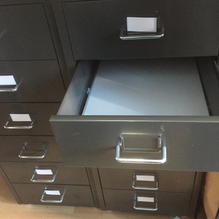
I picked up two of these in Ikea, ( they are €22 each with the family discount ) very useful , as you can see plastikard sheets fit inside very handy for all sorts of stuff and a fraction of Bisleys price etc dave

-
Almost all the O' dea collection has now been scanned in high resolution and is accessible via the nli website
-
Lovely layout. I always enjoy seeing your updates Dave
-
Your layout looks more and more like IE in the 80s. Love the pics , another good guy that can take pictures. Dave
-
Vacuum brake operation on GM 141
Junctionmad replied to Junctionmad's question in Questions & Answers
I must apologise to Garfieldghost and others here. I just finished reading some very interesting WABO tech documents and reading some old forums on vacuum systems fitted to export US locomotives It would seem and I can't confirm it. That the standard method that US locos used was air priority . the driver operated the train brake , which was air operated on the loco and behind the scenes the pneumatic automation combined with valves ensured that the vacumn was slaved to the air brake. The driver merely treated the train brake as if it was air , and the control system reduced the vacumn in proportion to the loco air pressure In that respect both the air and vacumn were " effectively " self lapping , ie the handle could be left in any position from barely on to full service and the system automation maintained a constant vacumn by relay valves connected to the exhauster. All this was transparent to the operator. Since both the air operated loco brake and the vacumn train brake were capable of progressive or partial release , the lever coould be moved back and forth in the service " area " and the system adjusted both the loco air brake and vacumn behind the scenes as appropriate. This pneumatic automation operation , in effect created a self -lapping vacumn brake. ( actual self lapping vacumn was quite rare as I said before ) The primary reason for this is US locos were typically built with train capable air compressors and an assumption that eventually operators would dump vacumn and switch to air, in fact the arrangement mentioned above allowed for a very simple switch over with no additional work by the driver It also meant for multiple unit working , both the loco air and vacumn connections had to made between locos , I presume that was the case with the CIE EMDs. It's turns out the whole system was more complex then I thought. In fact there may not have been a vac gauge in the cab ( was there ? ) Note that still isn't EQ brakes which were quite differebt Now making an equivalent Dcc brake is virtually impossible, because variable application of brake force isn't possible , there is just one service level brake deceleration ( in Zimo this is cv 349 ) so the best that can be simulated is the effect of moving the train brake lever to one fixed position, holding the brake on ( lap ) and then full release . Which would mean the Dcc throttle , brake lever would have two positions , on ( and lap ) , off with release But mike84c , the Dcc throttle is really cool isn't it. I have the bits coming to build one up but there's a lot of bits to make it all work. The faceplate is too big for my little cnc mf50 proxxon mill so that will have to made elsewhere ( Iowa scale engineering have only produced prototypes to date ) Ps. I also worked out what Release Auto was meant to be on the 141 brake console legends , it means that the loco brakes are released while the train brakes remain on !! , its spring loaded position and now the video on the DCDR cab ride in a 141 finally makes sense. Woohoo Dave -
I missed that too. it would be great to see stuff from before the 50s, even the Odea collection has its limits in relatively modern times. dave
-
Vacuum brake operation on GM 141
Junctionmad replied to Junctionmad's question in Questions & Answers
isn't it just , the lads in iowa scale engineering are to be congratulated ( as I did on their blog) for doing a very good job, with standard off the shelf electronic components ( getting the right rotary encoders is a hell of a job) . you could imagine it with a red 141 "hemisphere cowl", and the flying small emblem and it would be very "cool" . I Have the controller control board for the MERG units built up and the next job is to replace the MERG throttle wheel etc with these switches etc . ( the LCD will be driven from the existing MERG board . then a bit of glue software !!!!!!! dave -
The Station House, Glencairn, Lismore, Co. Waterford For SAle
Junctionmad replied to Georgeconna's topic in General Chat
jeepers , thats some "before" and after . dave