Signal Post
-
Posts
111 -
Joined
-
Last visited
Content Type
Profiles
Forums
Events
Gallery
Blogs
Everything posted by Signal Post
-
PM sent.
-
NIR Hunslet prototypical behaviour
Signal Post replied to murphaph's question in Questions & Answers
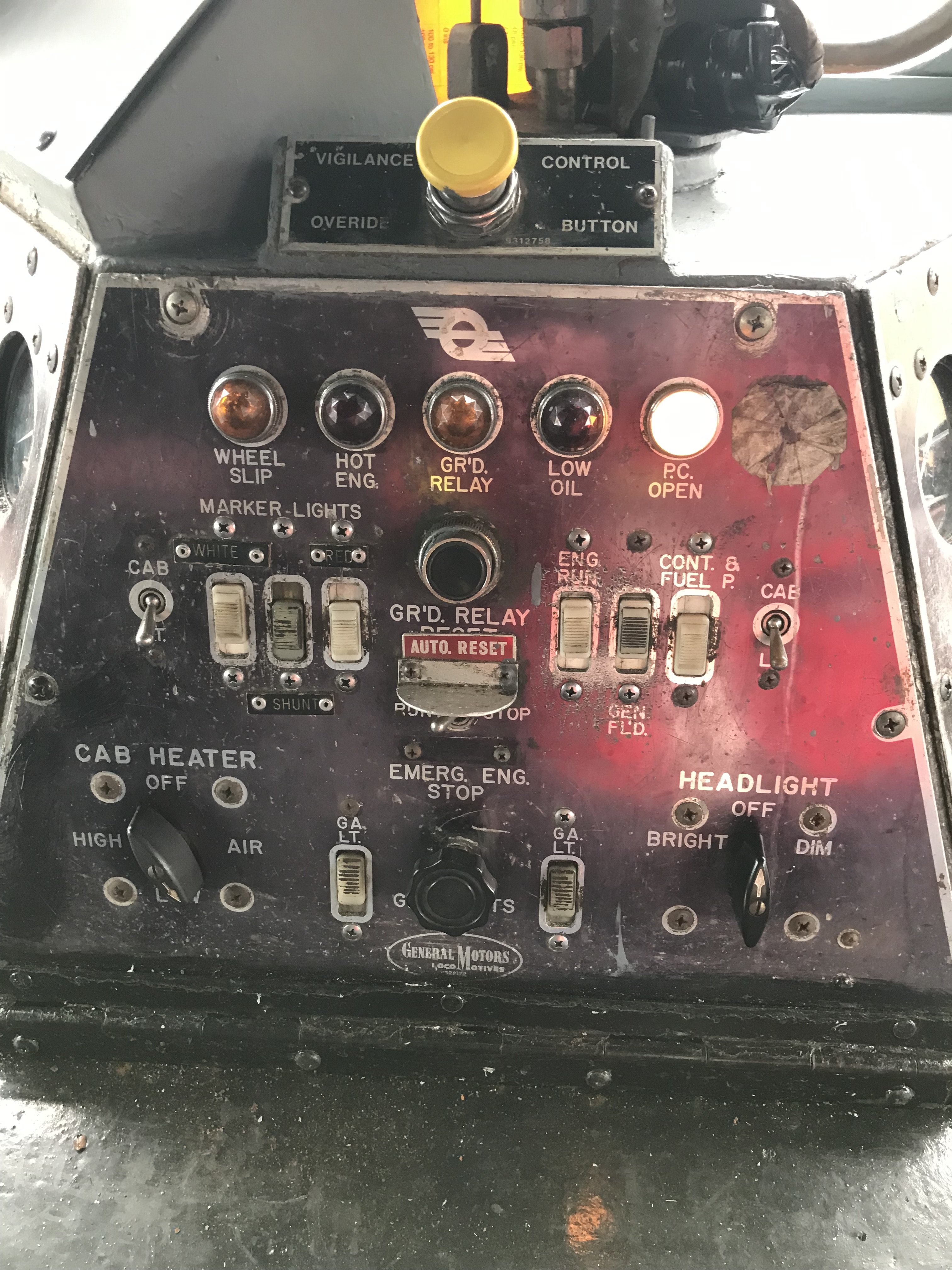
They are very good questions, I don't know the answer to any of them, however many of them would also be applicable to other diesels of the period such as the CIE A and C classes and the 141/181 and 071s. Just thinking about your question re the marker lights has set me thinking.....I was fortunate enough to get a cab ride in the baby GM B142 at Whitehead during one of their Diesel Days earlier this year (very much recommend same to any forum members with an interest in such matters) and one of the photos that I took was of the control panel for lights etc as shown below The Marker Lights switches are labelled as "White", "Red" and "Shunt" and the "Cab" light switches and Headlight switch (Bright/Off/Dim) are also visible on the panel. As far as I remember this was the No. 1 cab end. From the above it would seem that the markers would come on more or less simultaneously (assuming he turned both switches on for light engine running together). As regards shutting down the prime mover during a change of ends I would suspect not, I have heard that it could be quite difficult to get them started again to the extent that they (the A class) would be left running all night in Tralee (the environmentalists among us are probably reaching for their smelling salts at this stage...). I don't know if this was just a difficulty in starting from cold or a general reluctance to start. Hopefully some of the more knowledgeable folks will be along with more definitive answers.....
-
Tin vans, Tin vans, Tin vans... And some BGSVs too.
-
Congratulations Alan, delighted for you, very well deserved.
-
I travelled a long way to see this layout on Sunday. It was well worth it...stunning. To see not just the wonderful layout but also the BCDR locos and rolling stock most of it scratch built by Alan and Gareth, truly amazing. Thanks Alan, Kieran, Patrick and Gareth (of plasticard scratch buiding fame), whom I also had the pleasure of meeting at the show. Well done
-
Given your wonderful model-making skills I shouldn't be surprised to see a 4mm Paddy the horse make a cameo appearance soon....
-
That's a great photo. The "tour within a tour" was absolutely fabulous too! Those of us lucky enough to be sitting close to @Westcorkrailway on the bus were treated to a wonderful supplementary commentary on the CBSCR based on his absolutely encyclopedic knowledge of the West Cork lines and of what remains of it and a walking tour of lesser known (railway associated) parts of Skibbereen during the lunch break. I doubt if there's a single ex CBSCR sleeper in West Cork that he doesn't know the location of! Thanks again @Westcorkrailway for that, it was great meeting with yourself, @Mol_PMB and others from here for a wonderful day out.
-
Hi @Darius43 What Hornby DMU would recommend as a donor for the motor etc, I have the etches on order and have picked up some of the LMS (Airfix/Dapol) coaches that you mentioned, however I'll need to get some DMUs and I'm wondering which one should I be on the lookout for?
-
Welcome to the forum Dawn, I'm sure @Westcorkrailway and the other local members will make you most welcome in Cork, usually referred to (at least by it's natives) as "The Real Capital" of Ireland! I'm sure you'll enjoy Cork, lots to see and do, friendly people and a foodies delight, be warned though, it's addictive and a place you may find yourself wanting to come back to again and again..... Dawn modestly omits to mention that she also runs a YouTube model railway channel https://www.youtube.com/@modelrailwayquest with some very interesting content, her Loconory series of videos are particularly well worth a look (especially the recent one about the late Ian Allan (publisher).
-
IRRS Journals free to a good home!..........
Signal Post replied to seagoebox's topic in Free to a good home
pm sent -
You got it in one!
-
So sorry to hear your dreadful news Noel, but glad to hear that you and all your loved ones are ok. The photo of the paramedics working on your dog is wonderful, the care and compassion that they are applying to your furry friend comes across so clearly, we are all very lucky to have such caring people working in our emergency services. I'm sure that model railways will be very far down your list of priorities for a long time but glad to hear that at least your wonderful Gort layout has survived. If I can be of any help to you at any stage feel free to get in touch (I live close to Dublin).
-
Sorry to hear of your troubles David. @leslie10646's advice brought to mind the tale of a late friend of my father's (and myself). Said gentleman was visiting a city well known for the activities of it's pickpockets, he in common with many gentlemen of his era would have been in the habit of keeping his wallet in the back pocket of his trousers, however on this occasion he decided to employ diversionary tactics to reduce the risk of him being "out of pocket". His plan involved the use of a dummy wallet, fashioned from significant amounts of toilet paper and inserted in the approved position in his trousers whilst his real wallet was concealed elsewhere. Imagine his delight and the dismay of the errant pickpocket when he felt movement of his "wallet" and was able to intercept the criminal and prevent the loss of his cherished toilet paper!
-
That RPSI magazine, apart from showing the photo of Kilmainhamwood makes fascinating reading about the the RPSI which at that time was in it's infancy. It must have been an exciting time to be a railway enthusiast with the added bonus of minimal 'elf and safety concerns, hi-viz jackets etc....
-
Great info there @Antony, thanks for posting. It's rare to get that amount of text with the signalling diagrams, following the description of the changes gives a good insight as to how it all worked. Am I right in thinking that in later years (post 1977?) the line from Ballinderry/Antrim ran parallel to the up and down main lines and only connected up further along the down main towards Belfast?
-
Very sorry to hear of Michael's passing, I didn't know him personally but his work in the form of his kits from Leslie are a lasting legacy and have brought and will continue to bring a great deal of pleasure to many of us in the modelling community. May he rest in peace.
-
A pity it clashes with Model Rail Scotland and the Bangor show. Decisions, decisions.......!
-
Bucksdown Piccadilly Micro Layout
Signal Post replied to LNERW1's topic in British Outline Modelling
Sounds great. Taking on something that is small and achievable in a fairly short timescale will give you great satisfaction and added incentive for the bigger projects ahead later on. Looking forward to seeing this develop -
Wow! Never knew this feature existed...
-
Really looking forward to this talk.
-
Same here and from looking at the previous posts it appears to affect forum members on both sides of the Irish sea, therefore I presume we are using different ISPs?
-
Dawn Quest mentioned some problems with this model (at least I think it's the one that you've got) during her youtube livestream last night (the relevant bit starts at 36min 45sec):
-
What a wonderful video this is, it really deserves a much wider viewership, it explains the techniques involved in building this layout in a way that I'm sure would be appreciated by many non-railway people. As with all Patrick's videos made to the highest standards and with the gentle musical backdrop having, if I am correct, a local connection to the Knocklaughrim area (Slieve Gallion Braes?).
-
“The Donaghadee Branch and Harbour" by Gordon Hunt
Signal Post replied to leslie10646's topic in What's On?
For anyone who didn't get to see this talk it was absolutely superb, the first half dealt with the history of the harbour and railway and the second part was about the construction of the layout. The good news is that it will be displayed at the forthcoming South Dublin MRC show in October and then at the National Festival of Railway Modelling at the NEC in Birmingham in November. It's worth going to either (or both!) of these shows purely to see this layout. -
“The Donaghadee Branch and Harbour" by Gordon Hunt
Signal Post replied to leslie10646's topic in What's On?
I've been really looking forward to this talk since it was announced and it's even on my evening off! I have seen this layout (twice) and it is one of my favourites, it's absolutely stunning. Only sorry that I can't be there in person but Zoom is the next best thing.