Signal Post
-
Posts
111 -
Joined
-
Last visited
Content Type
Profiles
Forums
Events
Gallery
Blogs
Everything posted by Signal Post
-
Charlie Bishop of Chadwick Model railway did an interesting video on fitting lights to a BR brake van, may be of some use.
-
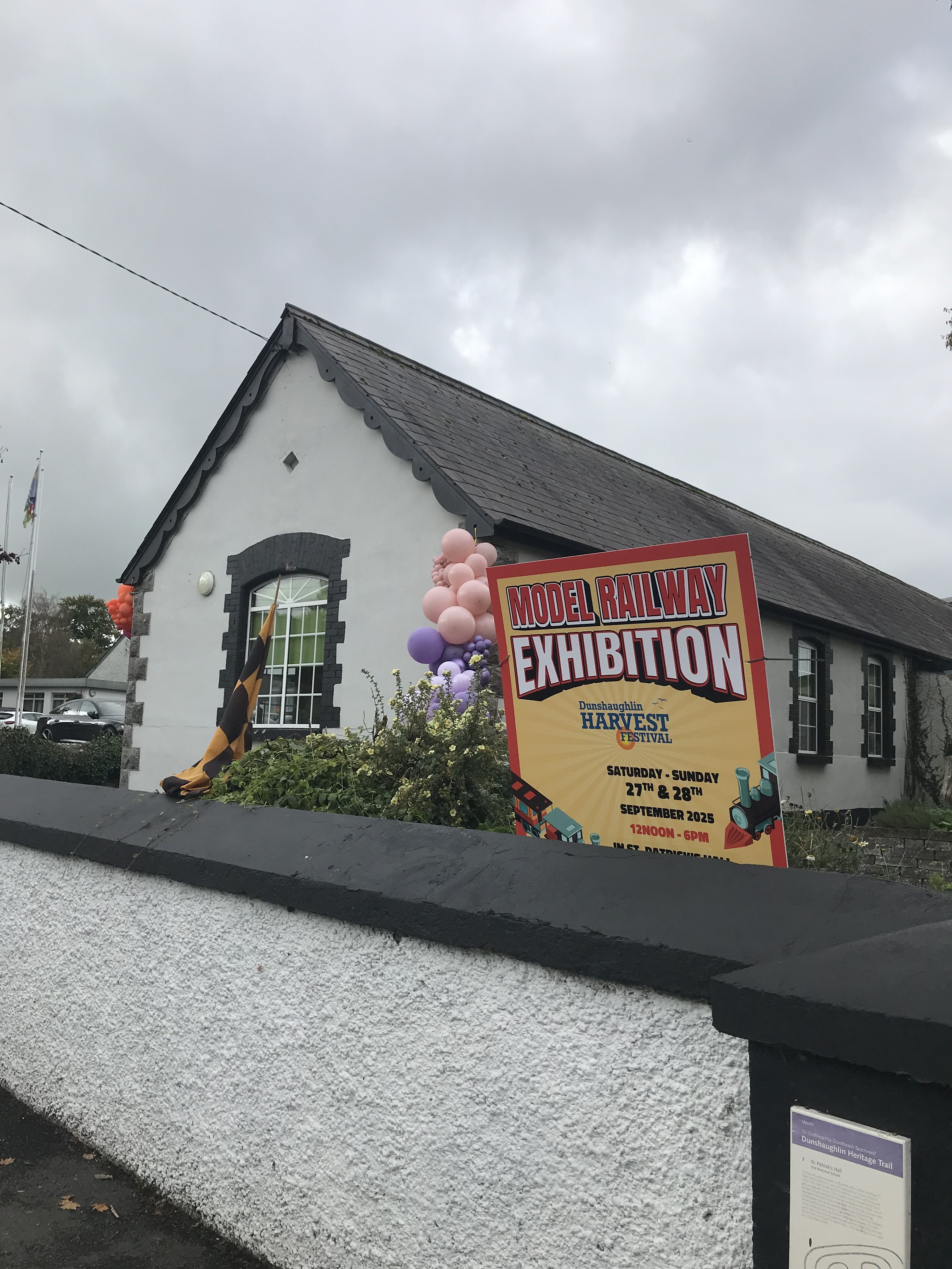
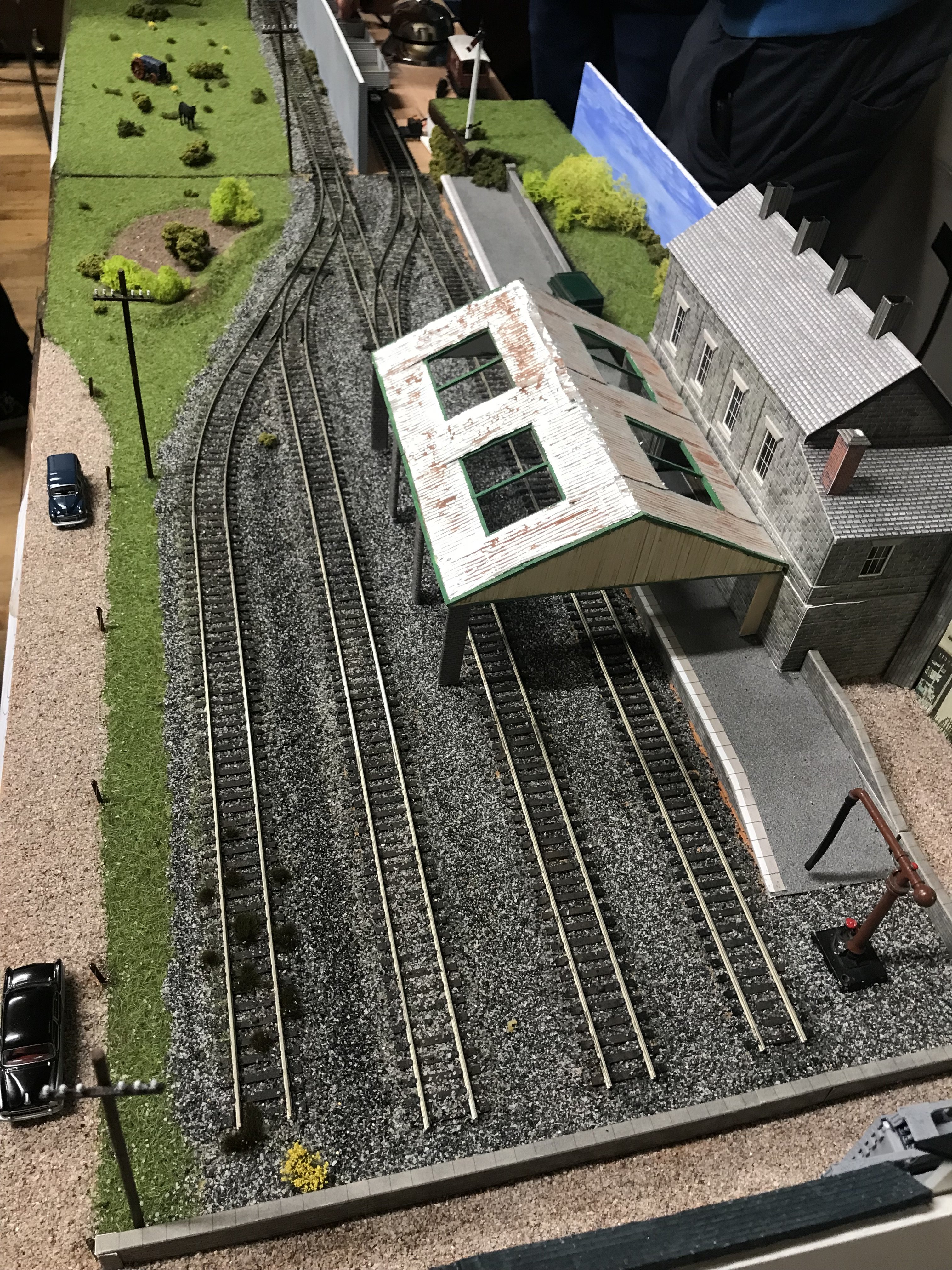
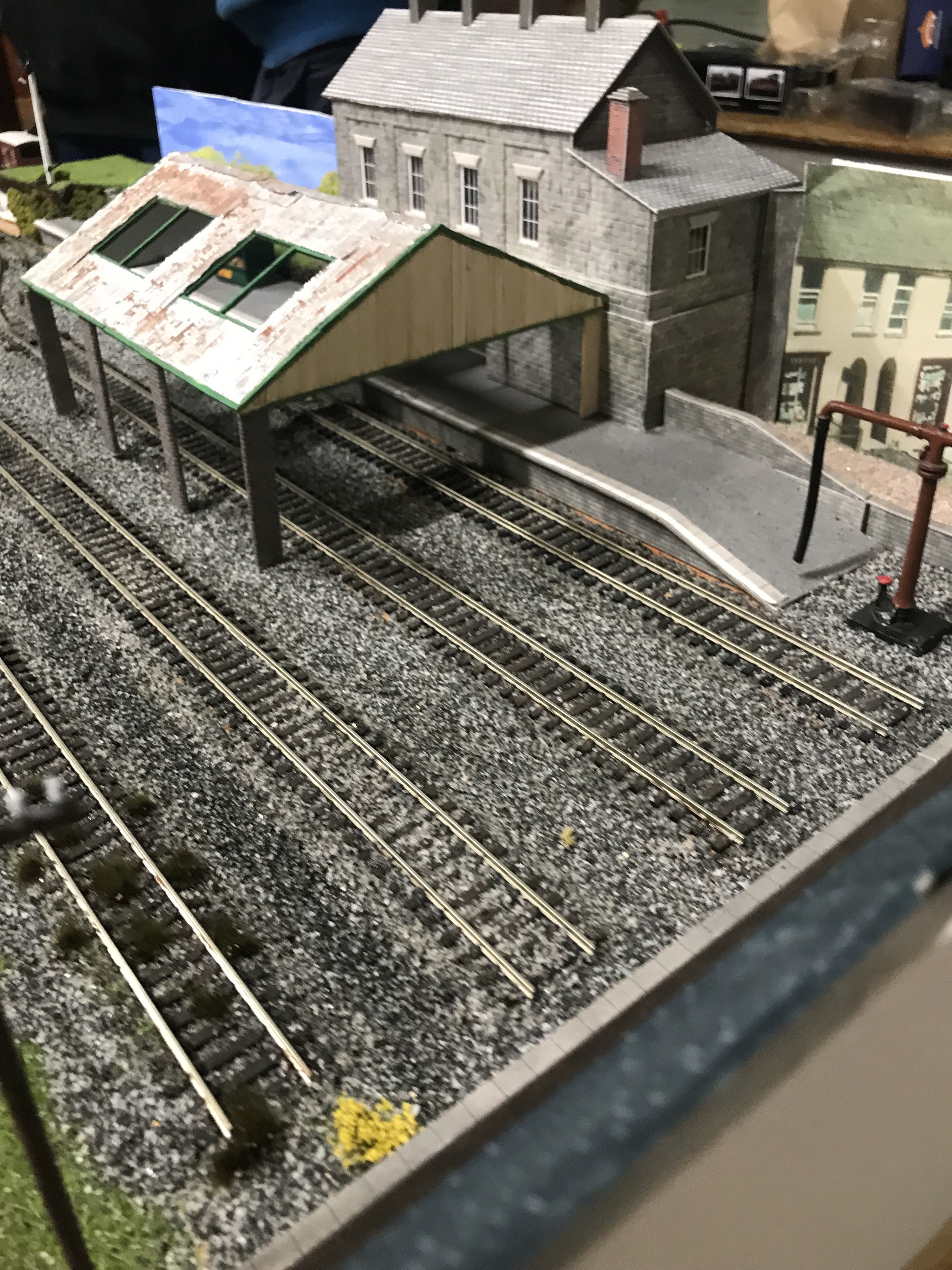
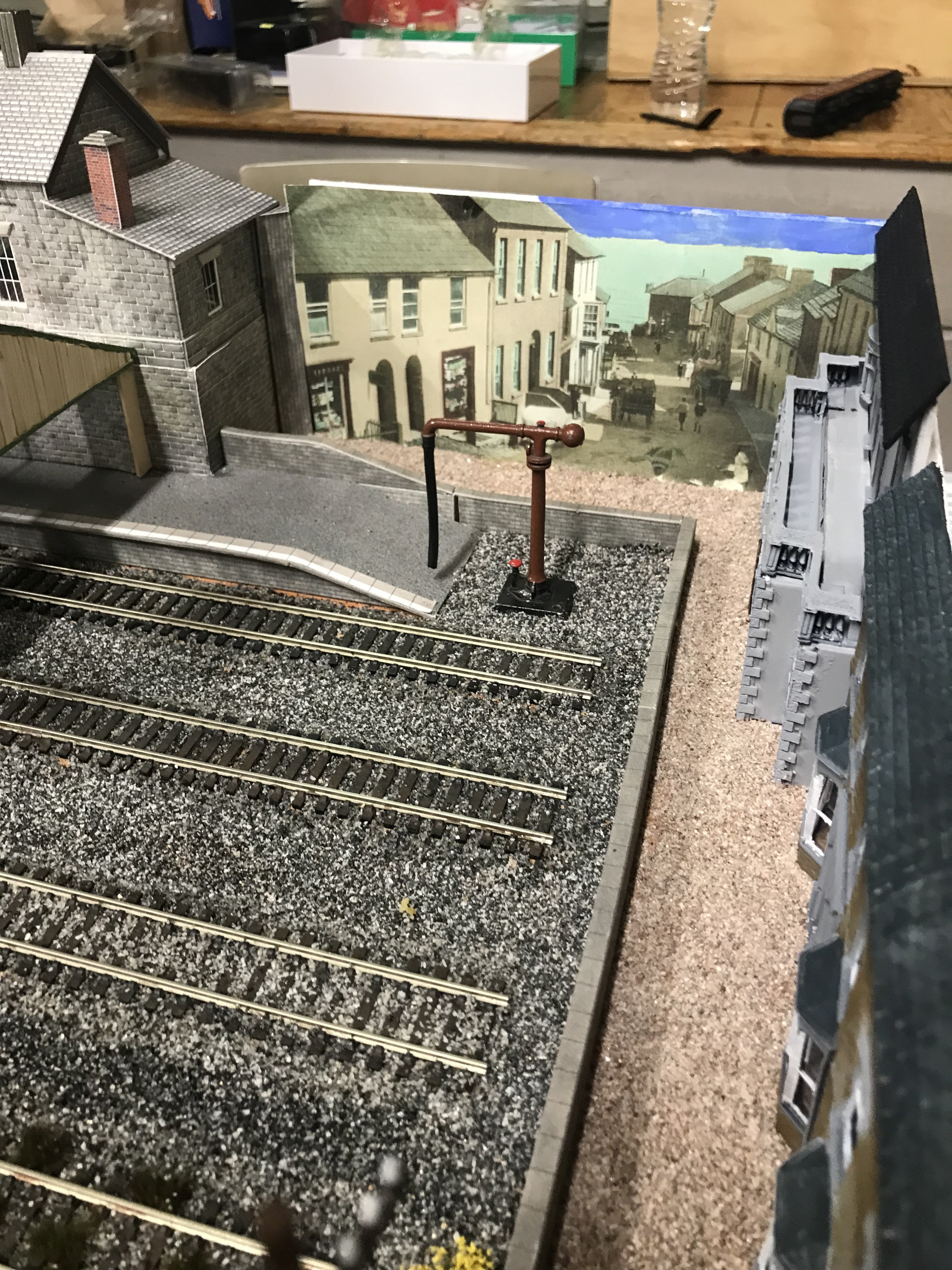
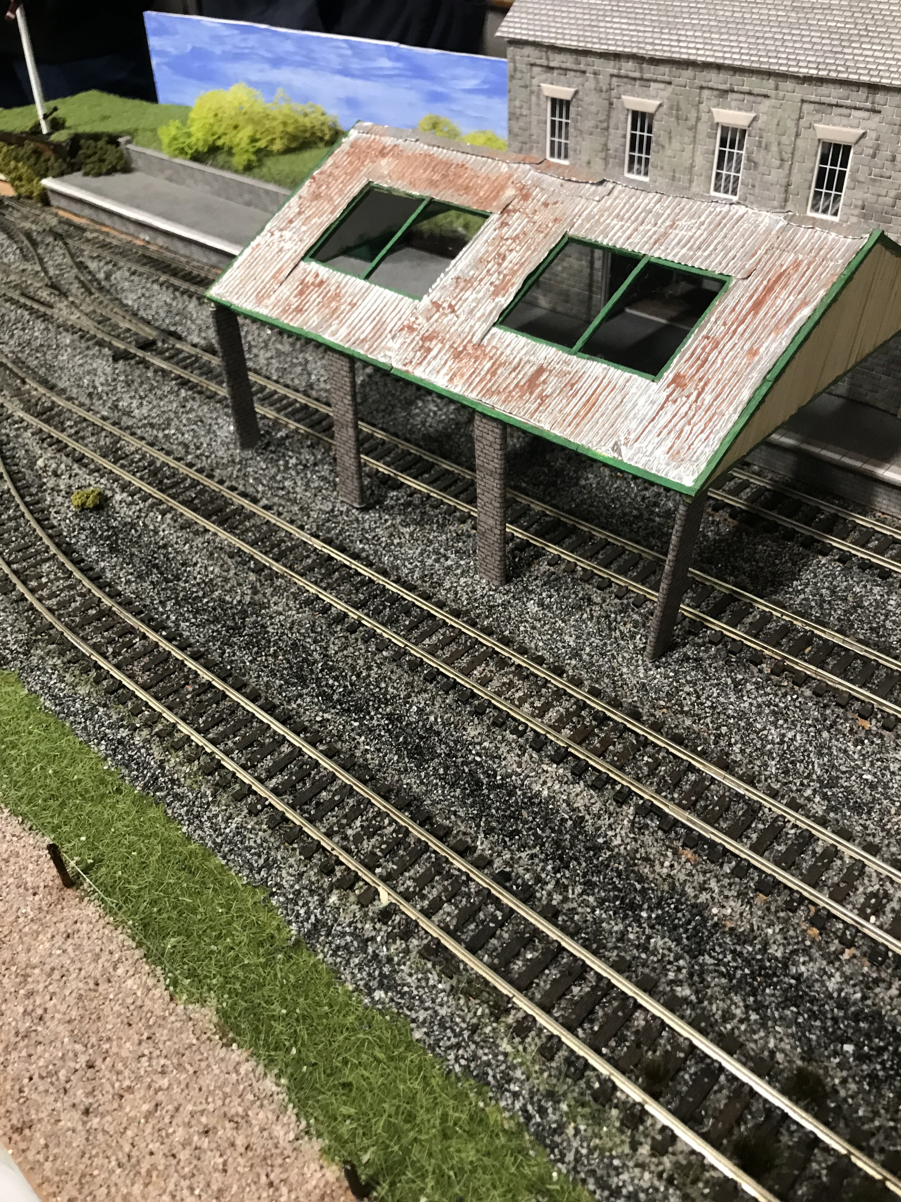
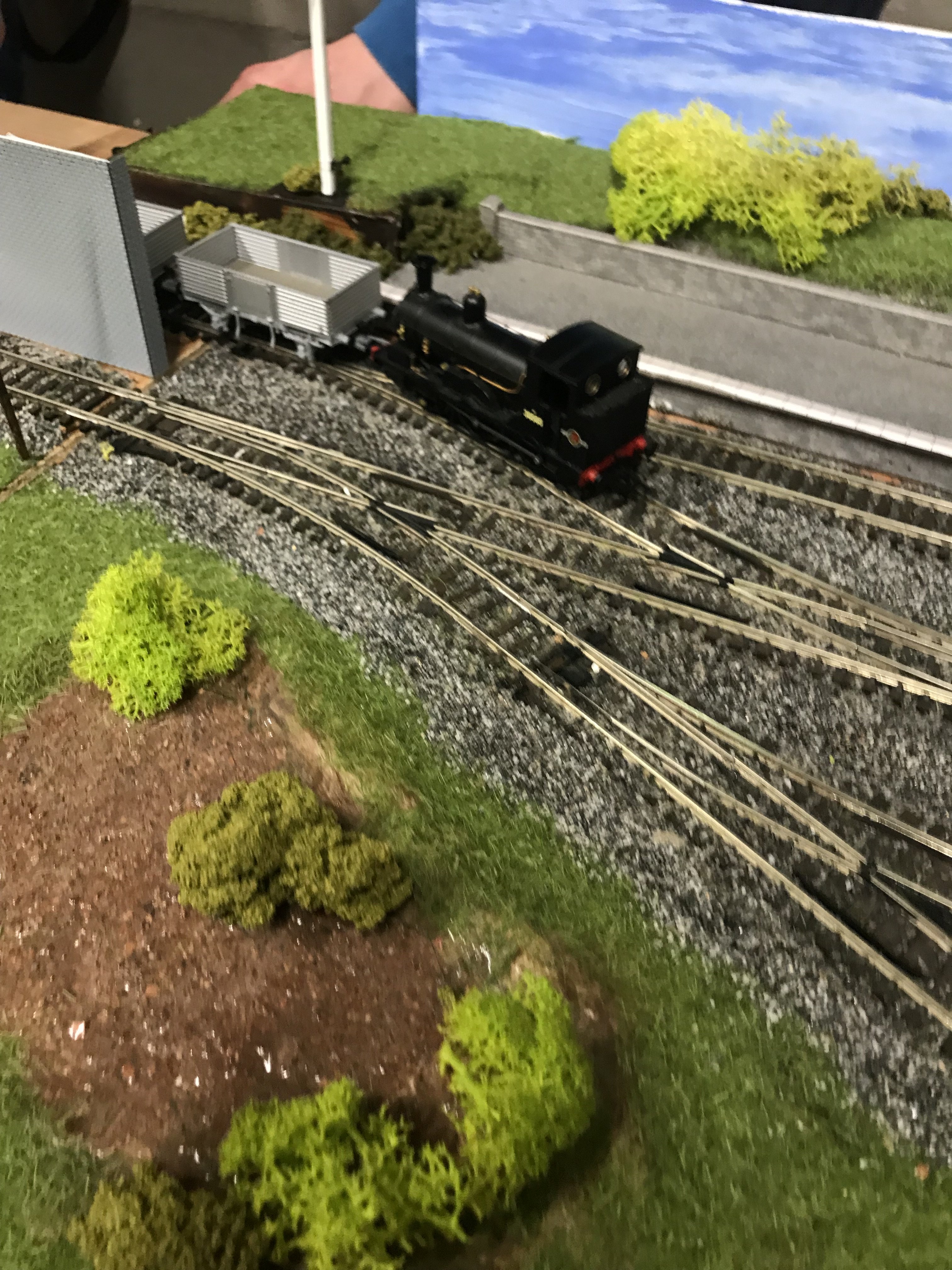
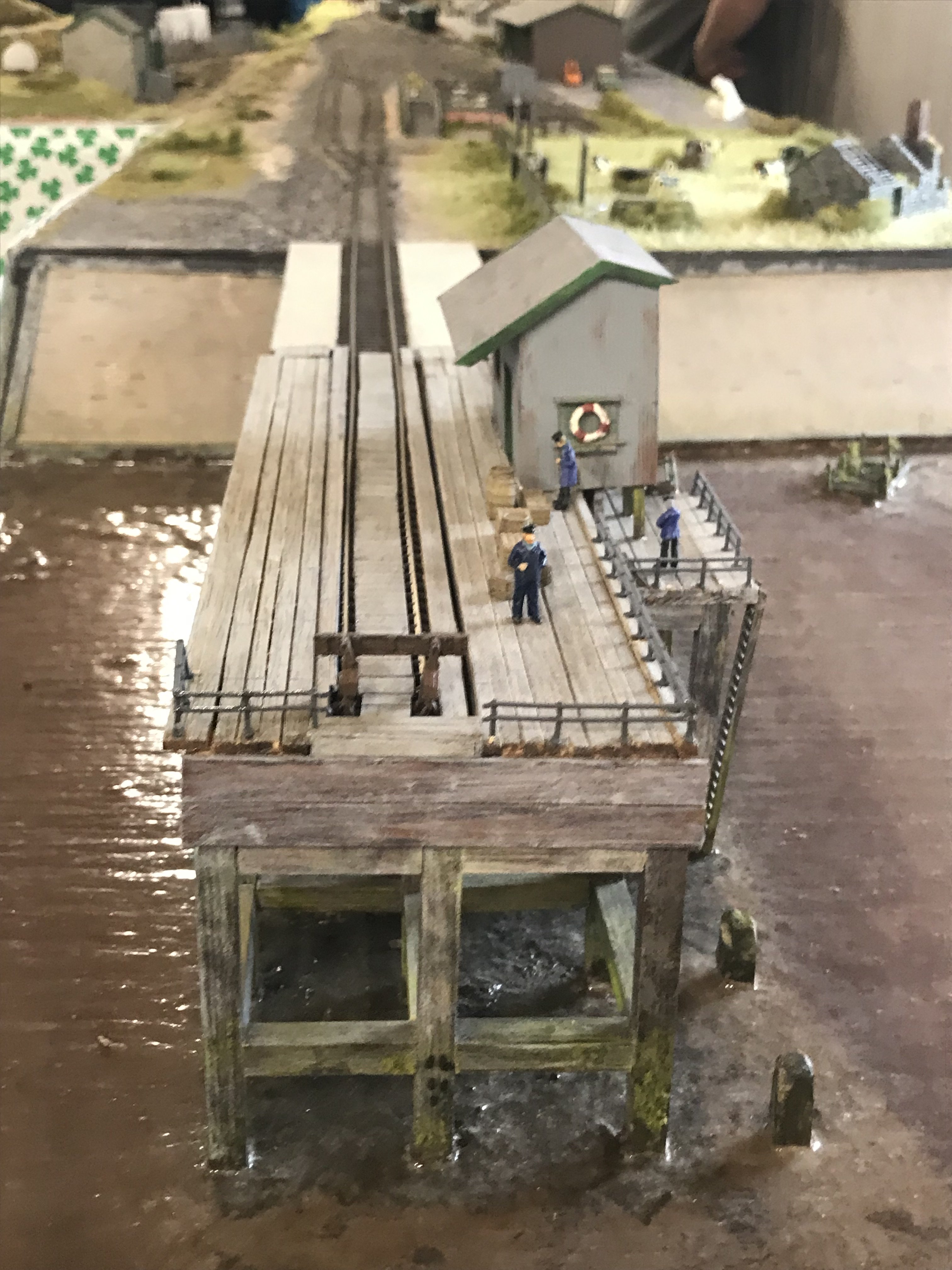
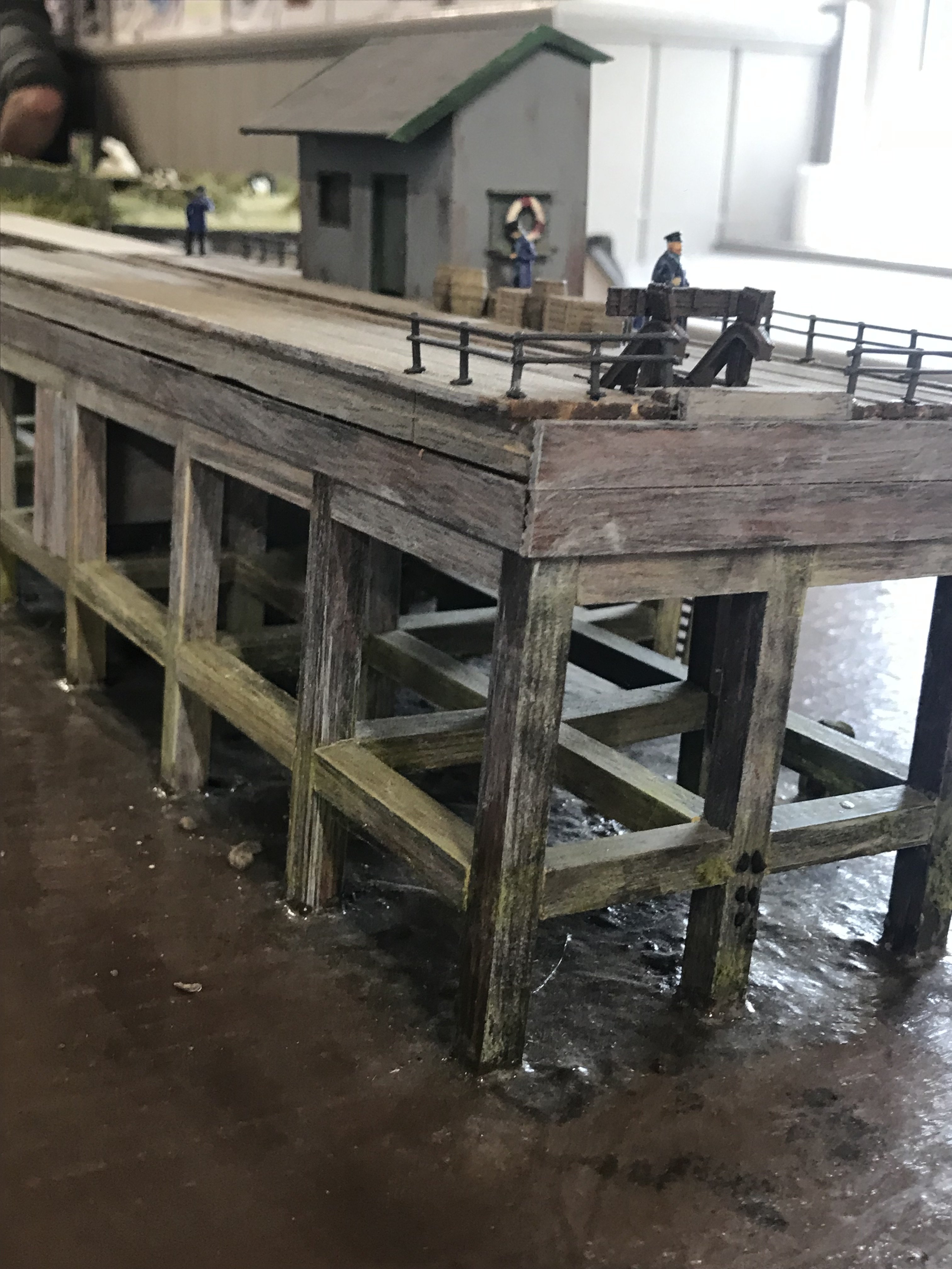
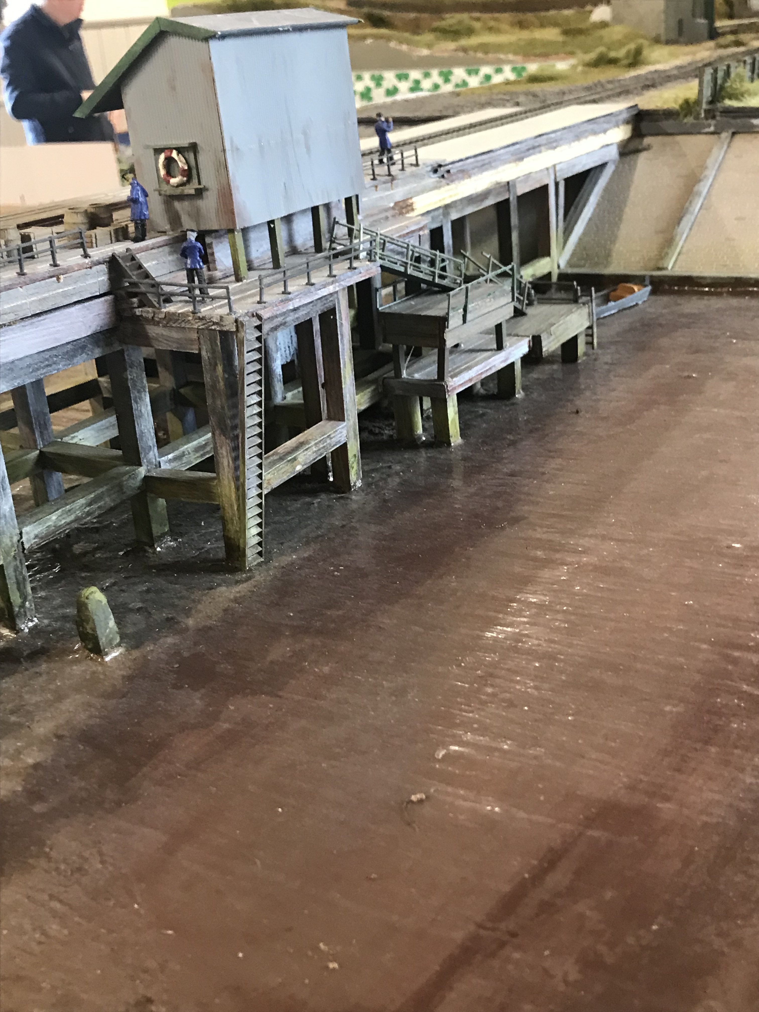
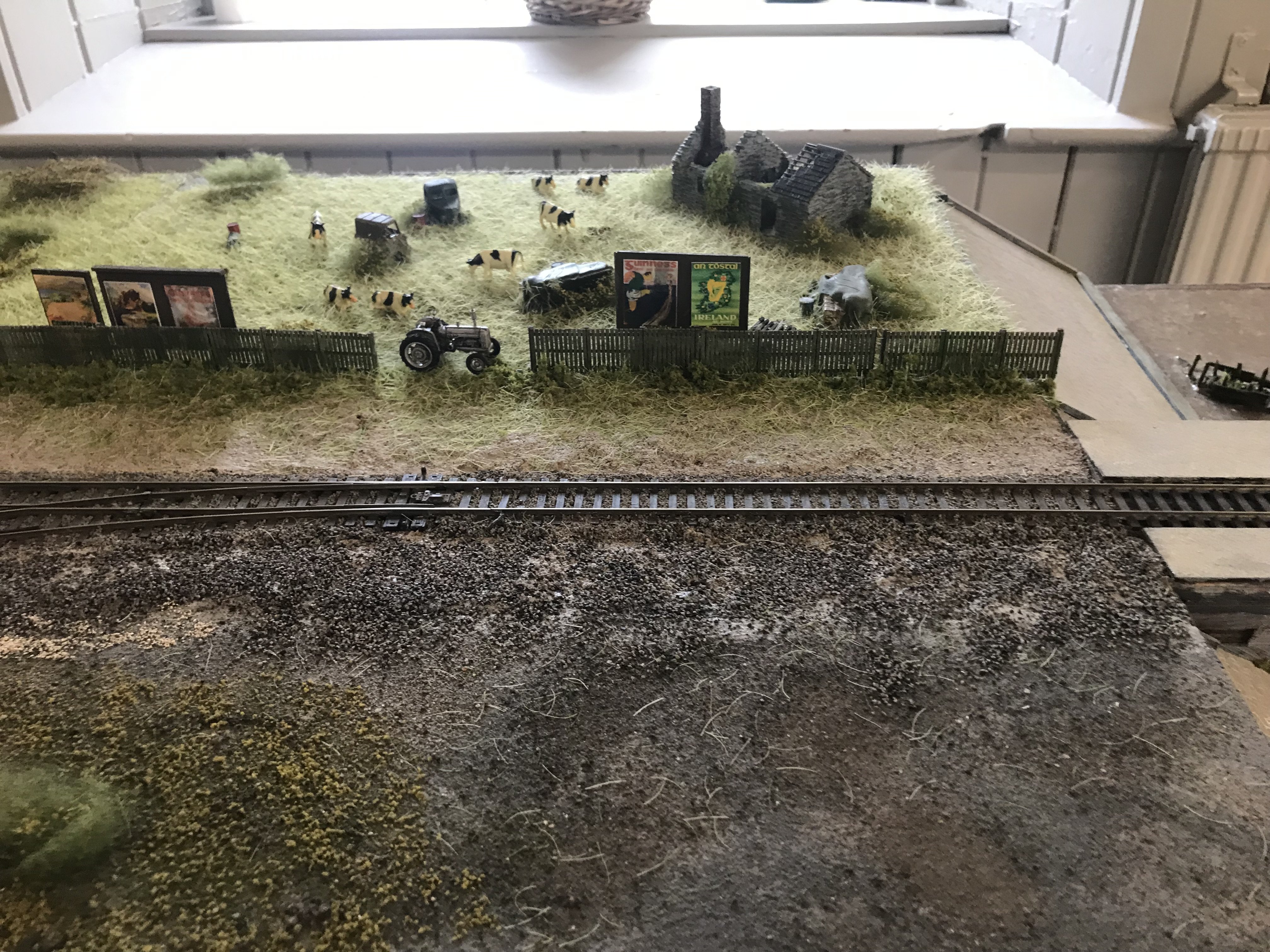
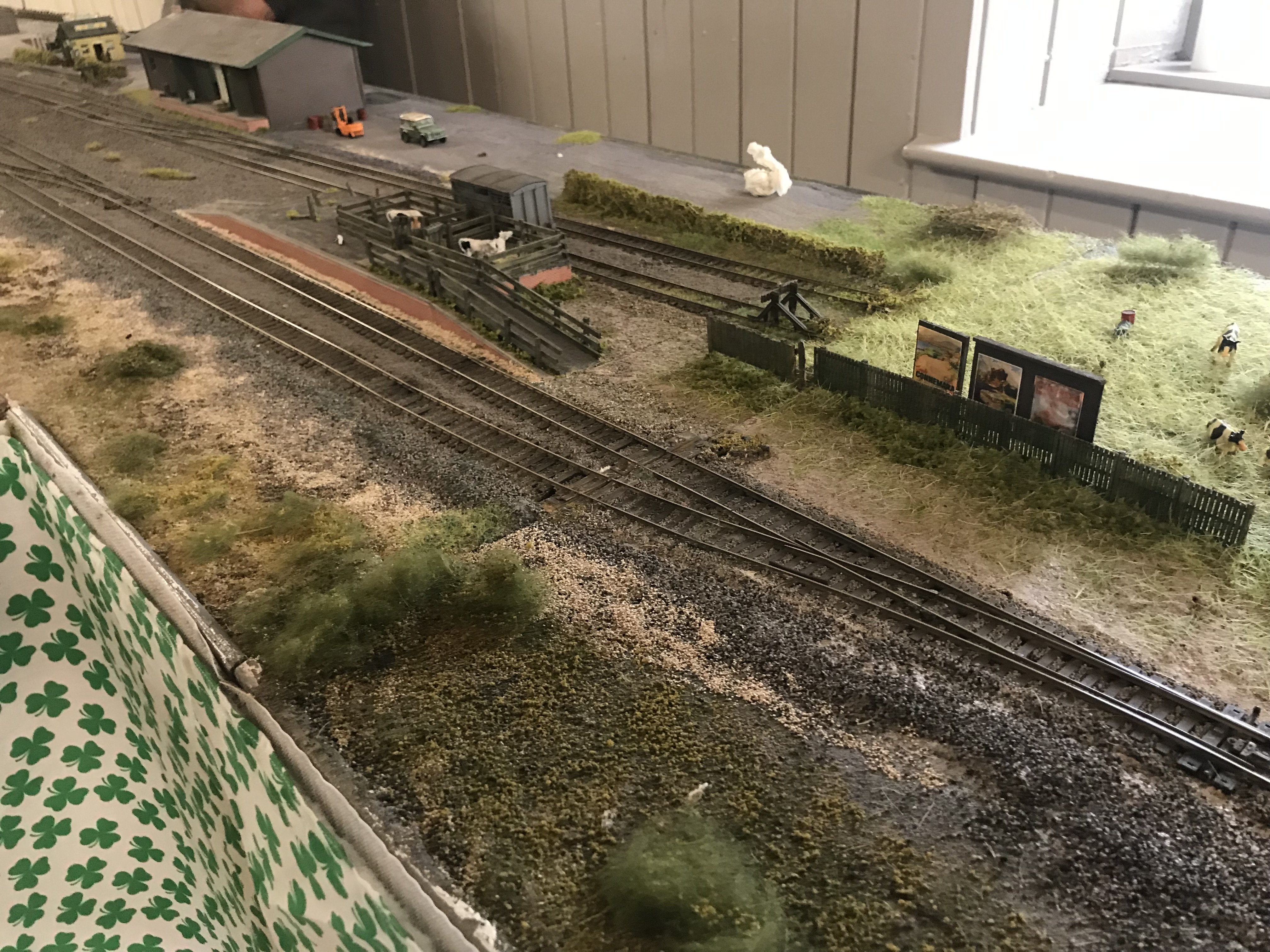
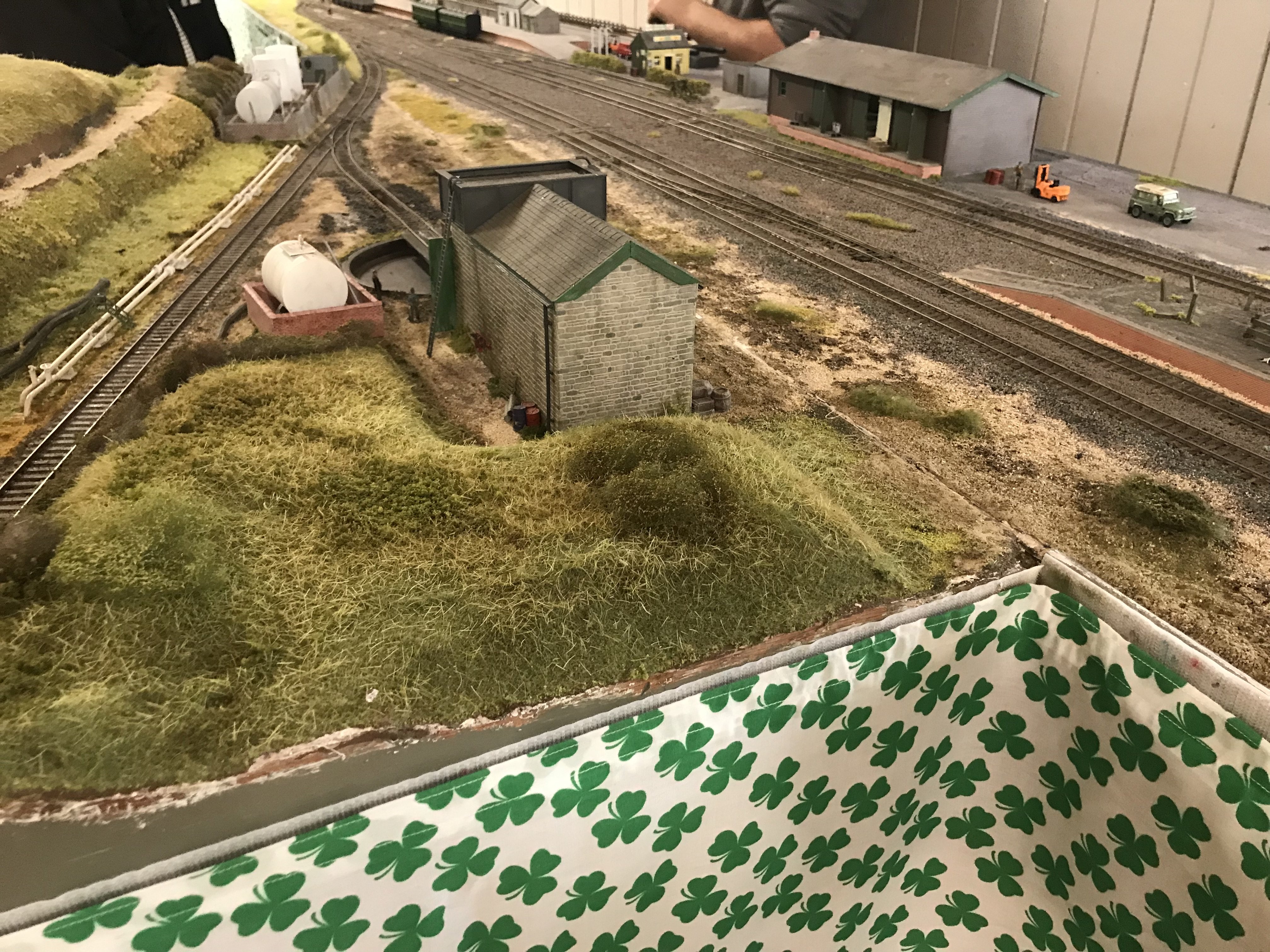
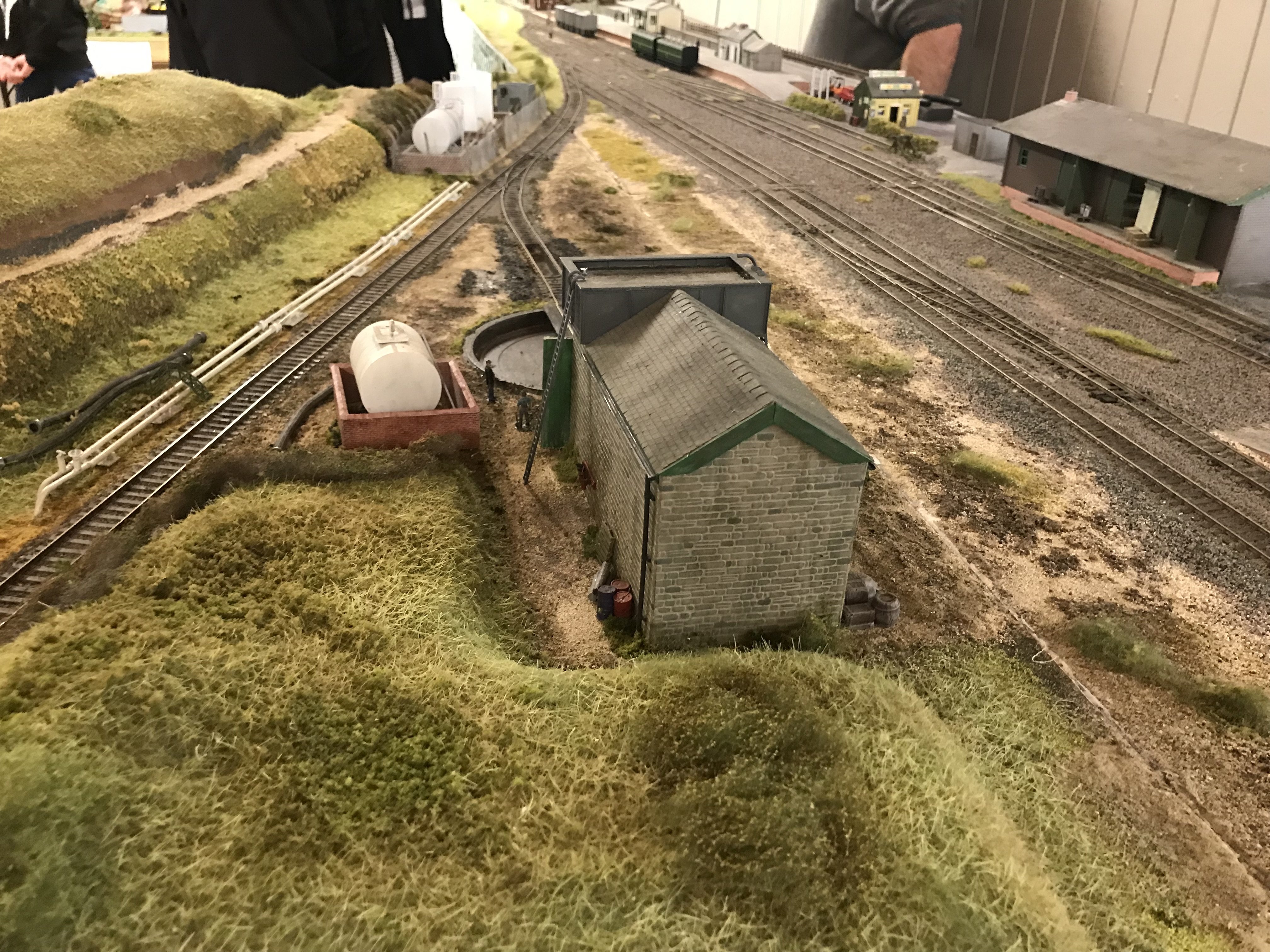
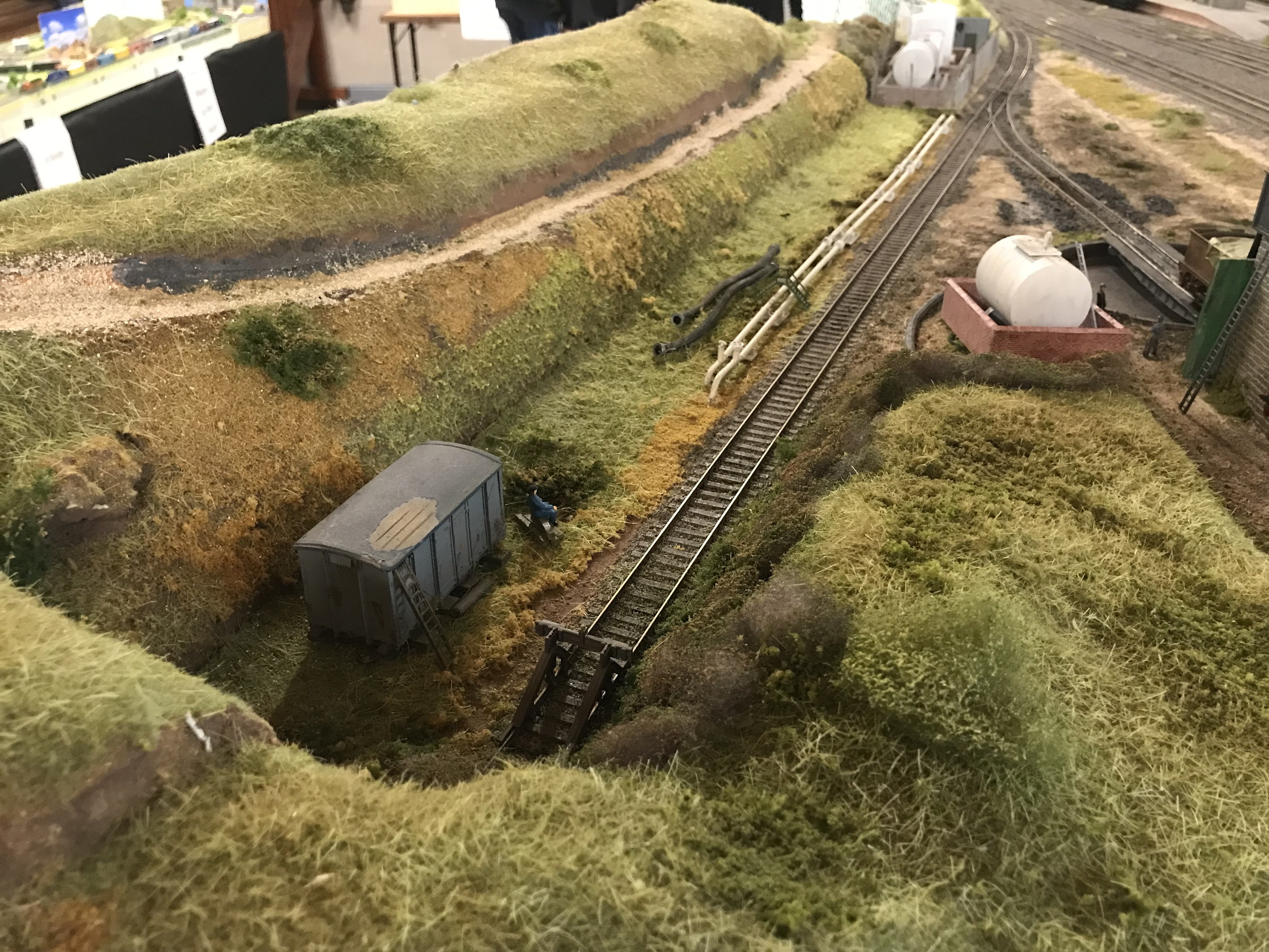
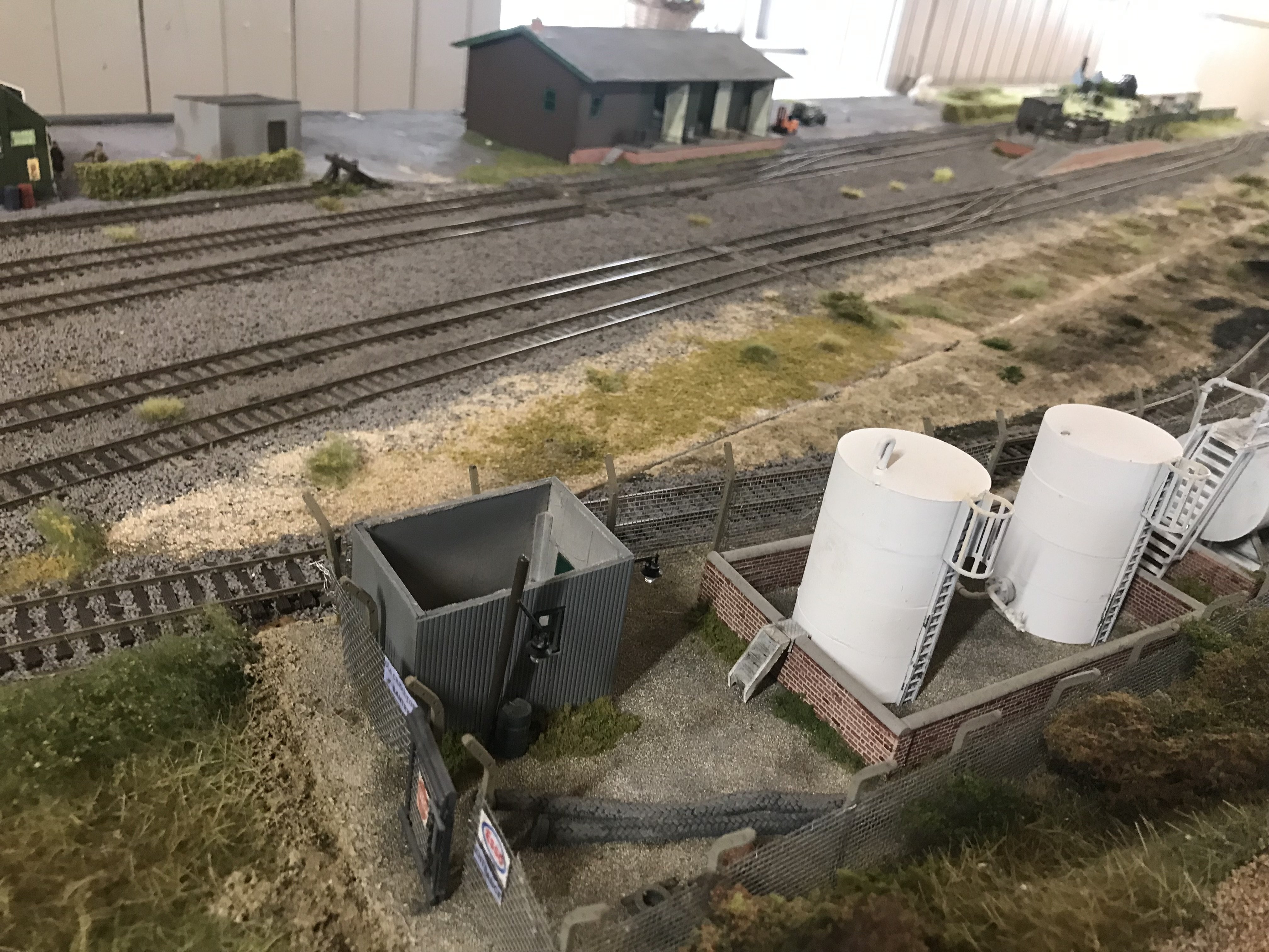
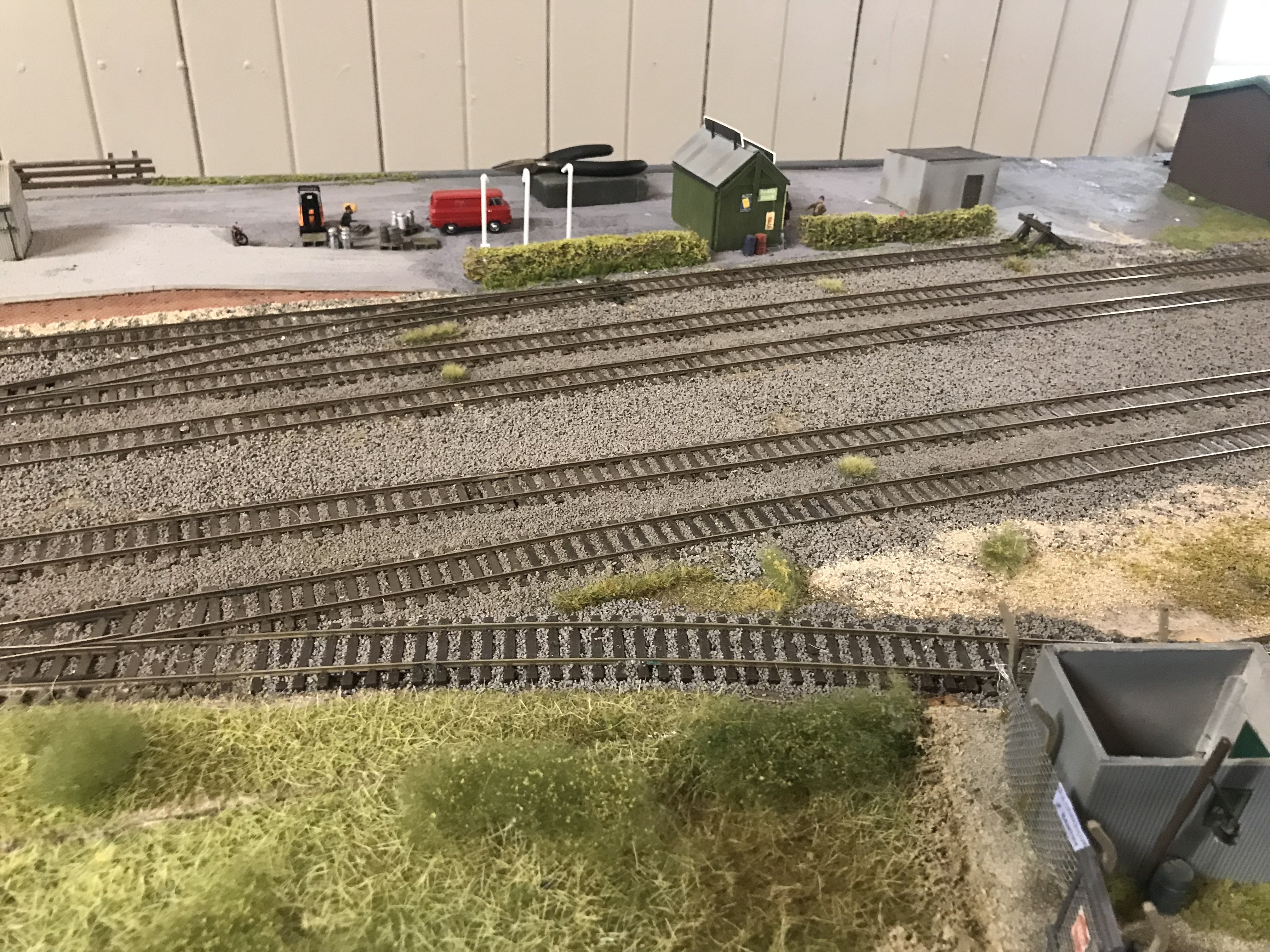
A few photos from the show today, no prizes for photographic excellence for me, I tend to get distracted when I am chatting to exhibitors and then forget to take the photo that I intended.....but that's part of the fun! A big thanks to @meathdane, @Metrovik, @LNERW1 and another gentleman whose name I omitted to get! It was great to see all three layouts, each very different but all inspirational, particularly nice to see the public and in particular family groups getting to see model railways, I'm sure many of the attendees would never have been to a dedicated model railway show so it gave the hobby great exposure in a local community event, well done, you are all great ambassadors for our hobby. I also enjoyed getting the chance to put names and faces to folks from this forum and discovering that a few other forum members live very close by! .

- 17 replies
-
- 13
-

-
Hope to get along to that.
-
Is that price a typo by any chance?
-
Clogherhead - A GNR(I) Seaside Terminus
Signal Post replied to Patrick Davey's topic in Irish Model Layouts
It might be worth trying a factory reset, although whatever about a single decoder going "rogue" or having a CV value changed inadvertently it seems unlikely that 3 of them (an EMD and 2 Crossleys) would have the same problem.... The way to perform a factory reset varies slightly from controller to controller (although they all do the same thing) and is not necessarily obvious to the uninitiated! It involves setting CV8 to a value of 8 (for the IRM decoders). I found this clip which shows quite clearly how to do it on an NCE PowerCab, note however that after performing this the loco address will default back to 3 and will need to be programmed back to your desired number. Personally I wouldn't expect this to cure the problem, given the symptoms that you have described. My next suggestion would be to try your loco on a friend's layout, preferably one that uses a different type of controller. I know that you have some friends up there with lovely layouts so it'll be a good excuse to see them again! -
Clogherhead - A GNR(I) Seaside Terminus
Signal Post replied to Patrick Davey's topic in Irish Model Layouts
I suspect that it is related to the controller. When you have switched the cab lights on (and the marker lights have extinguished) if you then turn the marker lights on with one press of the F0 button (and they re-illuminate) then this would confirm that the problem lies in the NCE PowerCab..... Yes it's a slightly scary mod given the risk of damage and the fact that the IRM locos are covered by a lifetime warranty..... btw it is possible to modify the CVs so that the marker lights wil be on at both ends simultaneously (as per the prototype), however with the cab end lights its all or nothing (ie both ends on or both ends off)... unless you choose to go waving a soldering iron about! -
Clogherhead - A GNR(I) Seaside Terminus
Signal Post replied to Patrick Davey's topic in Irish Model Layouts
No this isn't relevant to the problem that he is experiencing. The lighting mod described will change the lighting effects, basically F23 will then turn both front and rear shunting lights on (one red and one white on each end) as per prototype and F23 cab lights will then only switch on at front (in direction of travel). I don't think that Patrick's locos have been modified as evidenced by cab lights coming on at both ends. I have both modified and unmodified locos and neither will cause the marker lights to extinguish when cab lights are selected on. I wish it was this simple D.J. but I feel a bit more head-scratching will be required on this one...! -
Clogherhead - A GNR(I) Seaside Terminus
Signal Post replied to Patrick Davey's topic in Irish Model Layouts
Interesting......! I would agree with you that the problem appears to be with the decoder (or possibly controller) rather than any hard-wire issue with the locos, which is good news. My first thoughts were that the problem was with a CV (configuration variable) setting on the sound decoder, although this would seem unlikely it is not impossible, however given that the problem is occurring on both EMD and Crossley sound chips this possibility seems even less likely. Next area to investigate would be the controller that you are using, what make/model is this? Some controllers have an icon on the display that will show a light-bulb symbol when F0 (front marker lights) is selected on, if you have one of these does it remain displayed when the cab lights are selected to ON (I assume that you are using F23 for the cab lights)? Did you use this controller to assign the loco address to each DCC chip or was it done on another device (eg a LokProgrammer)? Questions, questions......! -
Clogherhead - A GNR(I) Seaside Terminus
Signal Post replied to Patrick Davey's topic in Irish Model Layouts
Wow Patrick, That is a wonderful video, would do credit to any professional documentary maker, mind you not too many documentaries have specially commissioned theme music..... In answer to the question that you asked in the video regarding the white marker lights being extinguished when the cab lights come on the short answer is no, you are not doing anything wrong. I have had a look at my own and using A3R with a standard IRM A class EMD decoder the white marker lights remain illuminated regardless of whether the cab lights are on or off, similarly with A55 with an IRM Crossley decoder. Figuring out what the problem is will take a little bit of work, so I'll begin by asking a few questions: Q1. Is it a standard IRM A class Loksound decoder? Q2. Has there been any changes made (intentionally or otherwise) to any of the CV settings on this decoder (other than assigning a new loco address)? Q3. Does the fault occur with the opposite direction of travel selected (on the video it is shown happening at the No.1 cab end (fan), if the other direction of travel is selected does the same thing happen at the No.2 end? Q4. If red (tail) marker lights are also selected on (F11 ON, on standard decoder) do they remain illuminated when cab lights are selected on? I would suggest swapping the decoders for a test ie put the sound decoder in A15 and the non-sound decoder in A3R. If the problem transfers onto A15 then it would indicate an anomaly with the sound decoder, however if the lights continue to work normally on A15 whilst the marker lights extinguish on A3R whilst using the non-sound decoder then this would indicate some form of problem with the loco.... Let me know how you get on with the above and then I'll probably have some more questions! -
I love the photo of Kilmessan station, nowadays it is a (quite nice) hotel and restaurant (The Station House) which is housed largely in the station building, the signal cabin is still extant and is used (as far as I remember as a bedroom, the goods shed is also still there. They have some black and white photos of the station on display but this is the first colour photo that I have seen. Thank you Ernie for posting this.
-
trackplan [Answered] Can a 'double deck' layout be achieved?
Signal Post replied to Josef2000's question in Questions & Answers
Charlie Bishop of Chadwick Model Railway has built a large layout involving a two helix design, one at each end of the layout. His lower level is non-scenic and comprises a large fiddle yard. The helix design and construction feature in a number of his YouTube videos sometimes as main features of a video or sometimes as an aside during an update on some other topic, having watched most if not all of his videos a couple of take-away points that I have got from them are: (i) The helices themselves take up quite a bit of room (as already mentioned by other posters on this forum). (ii) Necessary to consider access arrangements to rear of helix (adjacent to walls etc) for cleaning, fault finding or dealing with simple derailment (the front layers of the helix get in the way of reaching in towards parts near the wall). (iii) Consideration needs to be given to how to access underside of upper level baseboards, whilst it may be possible to lean/crawl in during early stages of construction, the presence of scenery, buildings etc on the lower level may make this impracticable once the layout is completed. Here is a link to one of his early helix videos -
Nothing in spam and e-mail should be correct, I got emails from Accurascale about delivery of some lovely grain wagons that I ordered the other day...these show up on my orders along with the Hunslets and Park Royals.... Have just noticed my Profile on my account and it lists my email address correctly.
-
Likewise. I have Hunslets on order but didn't get the emails today about them, they are showing up on my orders when I login to the Accurascale website (www.accurascale.com/en-ie......
-
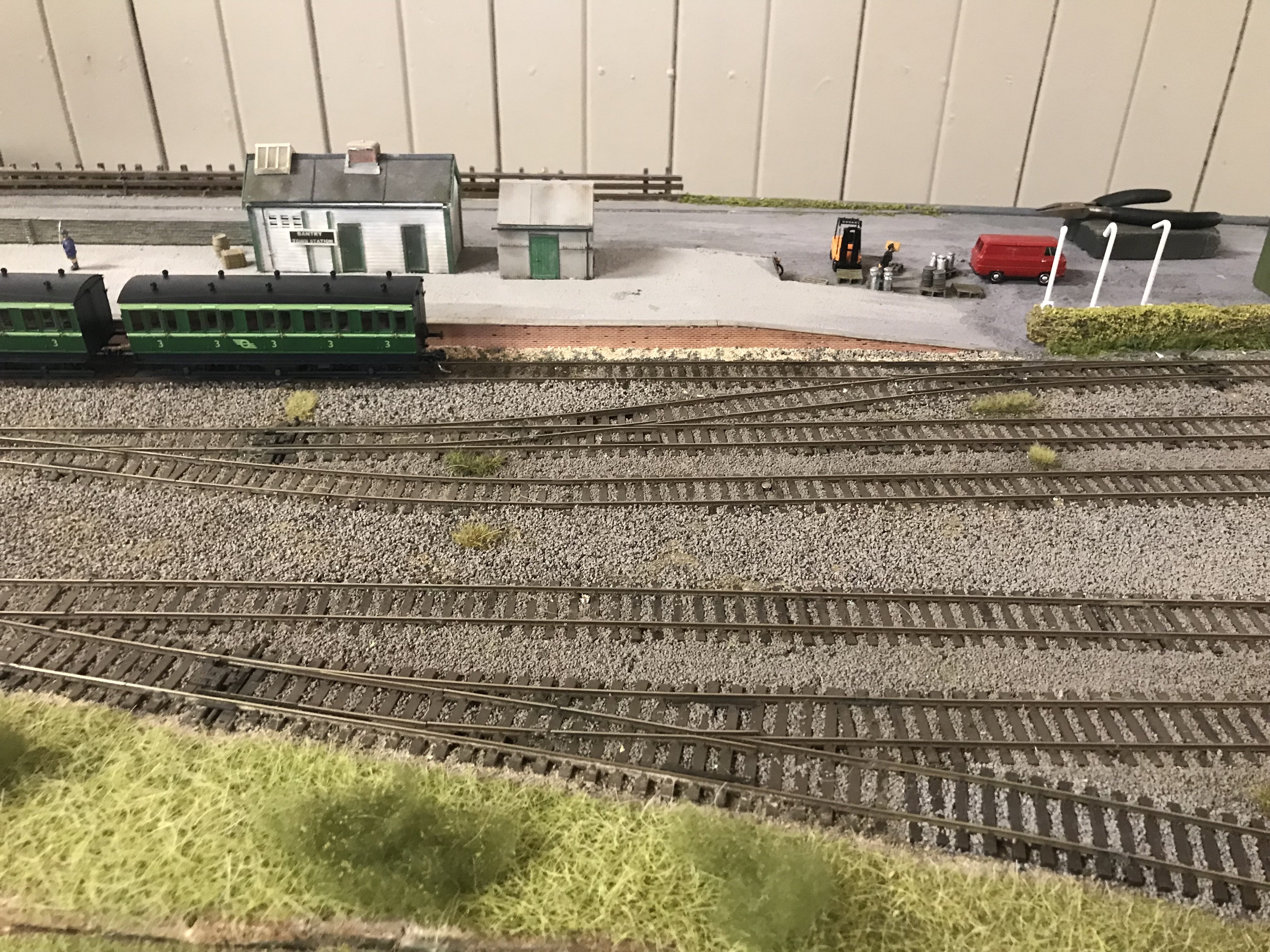
Bantry (on the correct side of the Irish Sea)
Signal Post replied to meathdane's topic in Irish Model Layouts
Saw your plan for a roller door on shed. We had some problems with rodent infestation of our garage (shed) some time ago and got a rodent control company out to look at it, one of their comments was that rats can get in anywhere there's a gap and one such place would have been the top of the roller door (there always needs to be a sizeable gap when the door is closed to allow for the door rolling up onto the roller when opened, also the same gap will allow a lot of air in during winter etc. There is apparently a type of brush type sealing that can be fitted but how good this is I don't know. Also the fact that I'm sure that you'll want some heat in the shed in winter to control temperature and humidity of layout might suggest an alternative type of door which would be easier to seal. Anyhow delighted to see Bantry getting a new lease of life, the more layouts we can have in Co. Meath the better. -
Might be as difficult as getting an invitation to Monday nights event! When I got home from work and saw my email (3 hours after it was sent) the application list had already closed, I'm glad for the lads in IRM to have got such a swift and enthusiastic response from the members on here but sad for myself (and I'm sure others) who have missed out. Trying to figure out whether I should dig out the telephoto lens and hide in the greenery adjacent to the Casino or perhaps don a white donkey outfit and return as the "ghost of donkeys past"* and look in the window.... *Folks with long memories of Malahide may appreciate the reference...
-
Not sure if this is what you were thinking of, it details a modification (soldering required) to make the cab lights directional and to make the shunting lights illuminate at both ends simultaneously. https://www.youtube.com/watch?v=e89UGtzitY8&list=WL&t=23s
-
Came across some more nice footage of Abrail 2025 on YouTube, some nice commentary on the layouts too. Looks like there were a lot of very impressive layouts at the show.
-
Thanks for posting this Leslie, that layout looks super. I had actually been toying with the idea of taking a trip over to Abrail as there were a number of things that I wanted to see there, so keep on posting, especially if you have any footage of Faringdon...
-
Newbie looking for a font but finding out so much more...
Signal Post replied to Fran's topic in General Chat
Welcome to the forum Fran. When you open that link, although it doesn't state the font used it does say "Glenderg Models", I would guess that this is the same @Glenderg who posts on this forum, he may know the font. Hopefully now he may now spot this question.... Hope this helps you in your quest. -
Wow, what a fabulous weathering job...
-
Oh no! The browny-grey and Norweigan blue I can take, but why did they go for the GREEN version, now we're going to have all the usual controversy over the shade of green and whether they are really Eau-de-Nil grasshoppers etc.....
-
Making an ‘E’ – the Maybach Diesel Model Assembly thread
Signal Post replied to Mol_PMB's topic in Irish Models
I should clarify that my "funny" emoji reaction to your last post solely relates to the last line! The rest of that post and indeed this thread is wonderfully informative and interesting, I never had a huge interest in the E401 class...until now. Now they are definitely on my bucket list. Your work on building this model is truly amazing, from doing the artwork for the etches through to obtaining the etches and then onto construction has been wonderful to observe and all done at a pace that even @Darius43 of this parish (who appears to be the record holder for rapid and wonderful construction of models) would , I am sure, be proud of. Thanks for all of this and keep it coming! -
Thanks Patrick, I think I've read of some of Gareth's models on other parts of this forum, looks like a super model. That's saying something, he must make outstanding models. Just ordered one, looking forward to getting it. Thanks for the heads-up John.
-
Wonderful stuff, very enjoyable to look at. Just wondering about the 25 ton brake van, firstly would I be correct in thinking that this is an NCC van, is this also the type that featured (sometimes) on the spoil trains to Magheramorne? Secondly is this from a kit or scratch built?
-
Stunning work Alan, just stunning.