Mayner
-
Posts
5,133 -
Joined
-
Last visited
-
Days Won
128
Content Type
Profiles
Forums
Events
Gallery
Blogs
Everything posted by Mayner
-
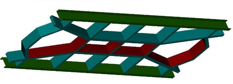
I originally planned to use 3D modelling techniques to produce the JM Design Tin Vans rather than as etched brass and whitemetal kits. I prepared this about 6 years ago though never got round to producing a 3D print. The basic idea is to use the print as a master for casting in brass or whitemetal. A number of local companies offer a resin casting services, using rubber moulds produced from 3D models. This avoids the layering effect with traditional 3D printing. At the time I was quoted around $800.00 for a mould for a coach body with a mould life of approx 30 uses. In the end I released the models as brass and whitemetal kits, due to the comparitivly higher costs associated with 3D printing or resin casting considering the potential level of demand and to achieve an acceptable standard of finish. In general JM Design covers its distribution and production costs but not its design or overhead costs.

-
It looks like several inventors were looking along the same lines at the time, in New Zealand its claimed that Richard Pearse a Timaru (South Island) farmer achieved powered flight about 12 months before the Wright Brothers. Much of Pearse's equipment was dumped in the farm rubbish dump and exhumed after his death. https://en.wikipedia.org/wiki/Richard_Pearse
-
Macken Street was one of my first gricing spots, on Saturday morning my father went into the Bosch distributor in Townsend Street. I remember watching an American style diesel apparently shuttling back and forward light engine across the bridge. This was in the late 60s Westland Row was a main line terminal and Grand Canal Street a busy locomotive depot. A few years later I traveled on the railway on school holiday trips to Bray, the line between Westland Row and Grand Canal St shed was a relatively modern and intensively operated railway by Irish standards with search light colour light signals with an elevated art-deco style signal cabin dating from the 1930s straddling the lines at the south end of Westland Row Station. While South Eastern Section suburban trains tended to work through to Connolly, the section of line between Westland Row station and Grand Canal shed could be very busy with light engine and empty stock movements in connection with main line train services to Rosslare and the West of Ireland. In addition to the light engine and passenger traffic, International Meat Packers plant on the West side of the current Barrow St station still received cattle by rail into the 1970s with a short loop serving a cattle bank off the up-relief? road between Grand Canal Street and Westland Row station. Des Coakham wrote an excellent article on Grand Canal Shed in the 1950s in Railway Bylines Summer Special No 5 (possibly 2002) despite re-signalling and electrification most of the infrastructure remained un-changed in its gritty industrial setting until the area was transformed by inner-city development and the demolition of Grand Canal St loco depot and the construction of the new station in its place in the early 2000s. Hard enough to walk under the bridge let alone drive . Erne and Macken Street bridges are still popular places for converting double into single decker busses.
-
Castle Rackrent inspired at least one other modeller to build a 36.75mm 7mm Irish broad gauge layout Dave Walker's Killaney appeared in the October and Nov 1985 Railway Modeller and was exhibited at several exhibitions including Hull & Chatham (where I actually saw it in operation. Killaney like Castle Rackrent followed a WLWR/MGWR theme and used some of Richard Chown's locos and stock before Dave Walker built sufficient stock to operate the layout including models of the WLWRs most modern loco 4-4-0 No 55 Jubilee, 2-4-2TNo 14 Lough Derg, 2-4-0 No11, MGWR 0-6-0T Bat and a GSWR 101 Class possibly assembled from a TMD kit. The layout was end to end junction terminus to fiddle yard which could be erected in an L or straight configuration, the terminus was fairly large country station and had a GSWR style overall roof similar to Killorgling or Tullow, turntable release similar to Castle Rackrent, double junction with diamond crossing between WLWR&MGWR lines, island cattle bank served by two sidings, large goods shed and single road loco shed
-
It amazes me more that IE have not demolished a building that has been redundant and surplus to requirements since Ballybrophy closed to goods traffic over 40 years ago. Perhaps the hope is for a section of roof or a wall to collapse so that IE can justify the cost of demolition on health and safety grounds. Presumably the railway is still liable to for rates on buildings whether in use of not and old dodge was to remove the roof from a castle or mansion to reduce the rates liabilities on large estates
-

Is Tomytech TM21 a suitable Chassis for N scale 141?
Mayner replied to purple's question in Questions & Answers
As far as I recall the Shapeways/Valve Design CIE 121 & 141 were designed to fit the Lifelike SW9/SW1200 chassis and the 071 was designed to fit the Lifelike SD7/9 chassis The Lifelike SW9/1200 still appears to be available from the United States under the Walthers brand https://www.walthers.com/products/trains/locomotives-traction/diesel/sw1200/scale/n-scale Microtrains SW1500 has similar trucks to the Irish locos at approx twice the price of the Walthers locos. Atlas & Walthers appear to have discontinued their SD7/SD9 locos, but used models occasionally appear on e-bay https://www.ebay.com/itm/Life-Like-N-Scale-Locomotive-Item-7767-SD7-LOCO-GN-566/263241145597?hash=item3d4a651cfd:g:XFYAAOSwsPlZyYZ5 John -
Bridehurst - SR Region 3rd Rail - Now no more.
Mayner replied to Georgeconna's topic in British Outline Modelling
I have a soft spot for the South Western out to Woking and Metropolitan Lines with their 1930s modernistic architecture and intense train services. The Waterloo-Alston service had the bonus of a cross platform interchange onto the Mid-Hants to travel in green coaches behind an N Class across the Alps to Arelsford> Could pretend I was on the Rosslare-Cork Boat Train but I was more interested in the Bulleid Pacifics & Urie/Maunsell S & N 15 4-6-0s -
I think the latest alterations are a big visual improvement and also give the impression of a station serving a market town with a fairly wide traffic basis compared to a small village & juts might have stayed open for freight under Railplan 80. The beet bank would have started life as a cattle dock possibly with cattle specials running to serve cattle fairs up to the early 70s, the mileage (gantry) siding would have served wagon load traffic basically any traffic not handled in the goods shed, including individual wagons of bagged cement in H Vans, bagged and bulk fertiliser/lime in open wagons, petrol/fuel oil, timber, steel basically anything. I would be inclined to replace the trap points with a crossover and move the bitumen unloading onto extend the gantry road into a headshunt, so you can position wagons further down the siding without having to disturb the bitumen wagons during un-loading. John
-
I worked from an office on Grand Canal Street about 15 years ago, the staff tea room was on the 3rd floor facing the Boston Yard. I ended up with a squint as I always had one eye on the window. The Boston Yard became increasingly busy after the Drogheda & Maynooth suburban services were extended to Pearse in the early 1980s both for reversing trains and storing trains trains during the off peak period. Most of the MK3 Push pull fleet were stored on the relief lines between Pearse & the Boston Yard after working the peak hour services from Drogheda.
-
The CVR even in its final years seems to have been something of a "spit & polish" outfit with smartly turned out locos and stock. The lighter colour of the underframe and bottom half of the angle iron on the end of 67 is likely to be a coat of dirt thrown up from running than the absence of rust, most Irish narrow gauge stock was vacuum rather than hand braked so the underframe was likely to be coated wit a combination or road dirt and brake dust. Several photos in E M Patterson's book indicate that van and wagon ironwork were picked out in black in contrast to the monotone in similar photos of GSR & GNR(I) stock. Although in its last years the railway was operated by a Committee of Management of Tyrone & Fermanagh County Councils, the interests of the Brooke and other landed/military families who promoted the railway were still strong and no doubt instilled a sense of pride/loyalty in the Aughnacloy shop staff. Funnily enough Ballinamore on the Cavan & Leitrim turned out at least one passenger brake van in green with snail & blackened ironwork as the rest of the passenger stock became increasingly decrepit in CIE days.
-
Wow! I heard rumors about the successor project to Greystones several years ago. If anything you have raised the standard of urban modelling even higher, its been well worth the wait!!!!!!!!!! John
-
A lot depends on the solder used, the cleanliness of the rail and screw head and the power of the iron. T The resin flux in multicore solder is unlikely to be up to the job of soldering to a screw head to a rail without some additional help. I have used "Powerflow flux' with multi core or plain solder for assembling handlaid track, the important thing is to thoroughly clean the flux reside from the joint on completion otherwise you get verdigras growing on the surface. You should be able to get Powerflow flux from your local plumbing merchant. If that does not work for you, simply pin the sleepers to the baseboard on either side of the baseboard joint with trackpins before cutting the rails. This arrangement worked for me on a modular N gauge shunting yard layout which survived a move from Ireland to New Zealand, I fitted strips of ply across the baseboard ends to protect the rail joints during transportation and storage.
-
Frequency depends on the size of the fuel tank, operating hours and milage/nature of work. Inaccurate fueling record/absence of a sight gauge on a 001 Class was one of the contributory factors to the Cherryville Junction collision back in 1980, the loco had worked a freight from Waterford to Mallow before being used to replace a faulty 071 on the Tralee-Heuston. Waterford shed staff forgot to record the fuel used when the loco was idling before working the train to Mallow. CIE used to re-fuel locos working freights on the main line at Inchacore using a long hose, I remember seeing IE refueling 201s off the mails and passenger trains at Galway loco depot on a Friday evening during the mid 1990s when I should have been out partying! Its not beyond the bounds of possibility that locos working freights are refueled by road tanker at places like Ballina or Bellview rather than returning the loco to Inchacore for re-fueling
-
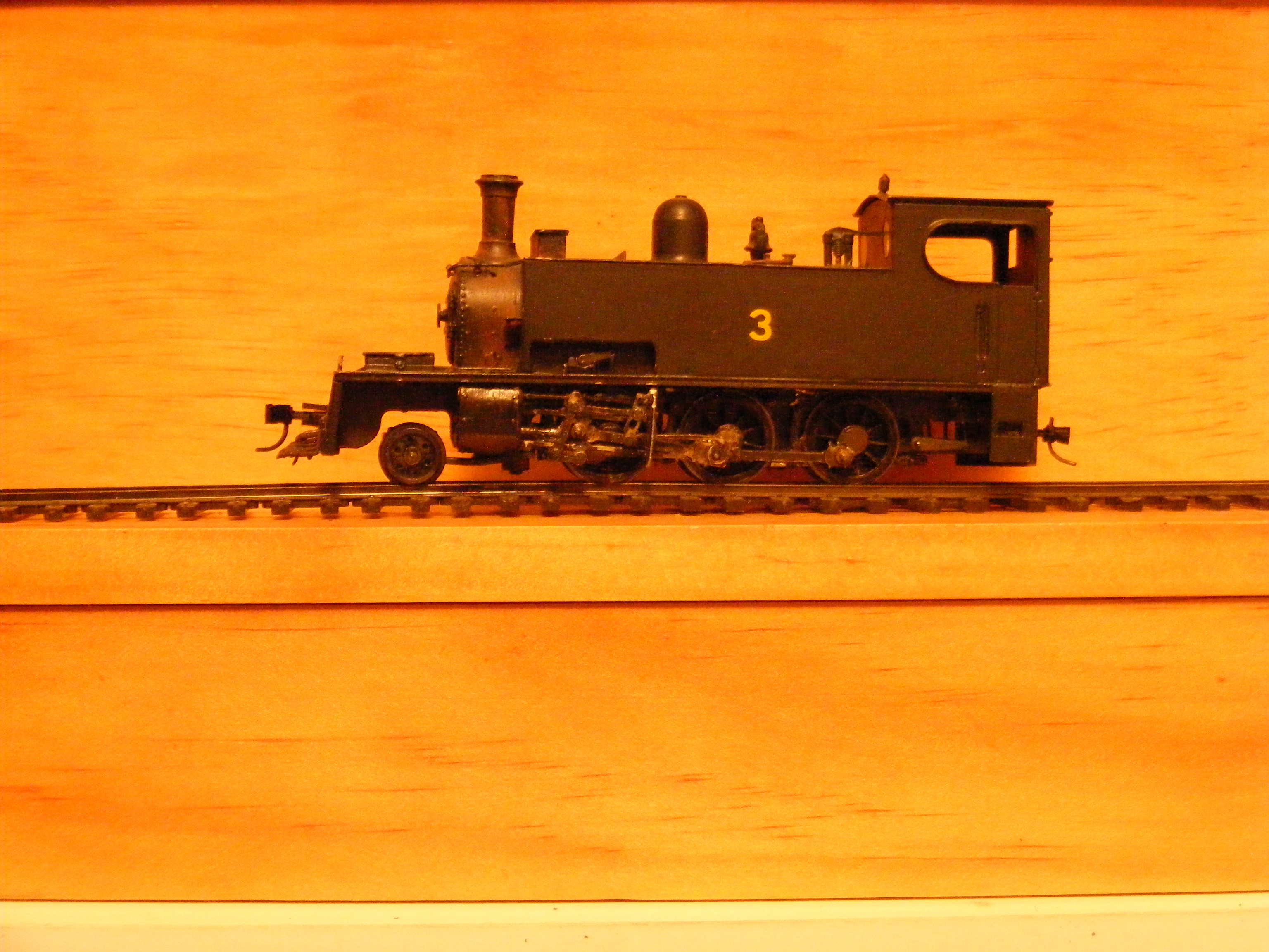
Snap. Very nice model as running on the Tralee & Dingle in GSR days. Same loco as running on the C&L in the late 1950s I need to do something with the front buffer beam pushed out by the Micro-Trains coupler pocket
-
The short loop in the goods yard almost seems to have been a standard feature at larger stations on the North Kerry & Burma Road possibly to speed up attaching tail traffic to passenger trains, perhaps the Cork-Waterford AEC railcar passenger attaching an insulated container on a 4 w flat from the local co-op or meat works with urgent traffic for the British Railways Waterford boat. The Dapol Prestwin chassis fitted with a wooden floor looks close enough to the flat wagons used during the early 60s for Guinness and general container traffic. =John
-
The 62'6" air braked wagons were converted to carry timber traffic. These wagons were used to carry container traffic on the Cork & Galway mail trains and became surplus to requirements for container traffic after mail traffic ceased in 1993-4. There was also a risk of of exceeding the axle load if 3X20' containers with a heavy product such as butter or milk powder were loaded on these wagons. The 62'6" wagons were in use in timber traffic by 1996 for traffic from the West of Ireland to Waterford & possibly Clonmel plants The 4 wheel wagons were a later conversion as timber traffic built up to serve the particle board plants at Bell View & Clonmel. The closure of the Ashai plant in Ballina and failure of Bell Lines in 2007 lead to a substantial drop in container traffic, that would have made most of the 4w flats surplus to requirements for container traffic. Timber traffic ceased completely around 2002-3 when IE suddenly discovered that it was un-profitable, traffic resumed from the west to Waterford when a new contract was negotiated with Coillte, though after 20 years IE & Coillte have not sorted out a rail connection to the log yard at the Waterford Plant, though I suppose it keeps the local hauliers happy
-
The building on the right looks suspiciously like it started life as a locomotive running shed and the line to the left of the A Class as a passenger station, which would have made sense as the Dundalk & Enniskillen would have had its own station, running shed and works before the GNR Works and Loco depot was established. http://www.geograph.ie/photo/1030219
-
Barrack Street Goods Yard. The connecting line to the Dundalk Newry & Greenore Quay St Station & Dundalk Port at upper left line to the Square Crossing Clones, Enniskillen, Omagh and junction with the GNR (Dundalk South Junction) main line bottom right. The yard was closed in the early 90s and freight traffic transferred to a new yard on the old Irish North Western connection at Dundalk Junction. Site now occupied by Civic Centre/Council offices. Interesting the "Fitting Shop" beside the DNGR connecting line was this part of the old Irish North Western works
-
A smoke box will weather differently to the boiler and smoke box cladding as its exposed to direct heat from the smoke from the fire and exhaust steam. So a rusty or burnt smoke box was quite prototypical on a hard worked loco.
-
The DLK log cradles were designed to fit over and straddle the 22'6" flats, the long channel visible in the photo is part of the cradle as opposed to part of the wagon chassis a fairly unusual arrangement.
-
Driving a government vehicle I was often been stopped for suspected speeding but never in my own private car. We work under a similar performance management system to the traffic police, so most cops have a fair idea we are not going to be difficult at being stopped unnecessarily by another public servant trying to reach their quotas and keep their boss and Government Minister happy. Though again I might just have been lucky .
-
I disagree: Both the Mayo and Sligo lines have a faster more frequent passenger service than they ever had, the Bus Eireannn service from Westport Castlebar to Sligo via Ballina is more direct and scenic than by rail through Claremorris The Burma Road (Sligo-Claremorris) closed to passenger services over 50 years ago was primarily intended for people travelling to Limerick, though in 1897 the 5:45 a.m. from Sligo connected into the MGWR down Limited Mail at Claremorris at 11:00 arriving in Claremorris at 11:36. At that time there appears to have been a morning and afternoon passenger service over the Burma road, the afternoon service was a mixed goods and passenger train or for a time machine! I am not sure if it was possible to travel by rail from Sligo to Castlebar by rail before the Burma Road closed to passenger traffic when the service was down to a single return Sligo-Limerick working
-
Beautiful drawing very old with handbrake on one side only and wooden centered wheels. The requirement for a handbrake on either side most likely came in after 1900. The East Downshire Steam Shipping Company operated out of Dundrum (Co Down!) and had a fleet of private owner wagons that operated on the County Down. The wagons apparently ended their days in internal use at Dundalk Port after the County Down Main line closed. Provincial Wagons once produced an East Downshire coal wagon http://www.provincialwagons.com/3.html I have a large scale drawing of the Irish "standard" wooden bodied open wagon used by the Great Northern & the Southern Companies from about 1916 onwards, if I find it I will scan it!!
-
Sidelined locos and freight cars (coal and oil tank cars!)were quite noticeable when we were on holidays in the States in 2016, there were articles about lay-offs and stored locos in the local papers in Western States. A lot of the locos in the UP video look like they were due for replacement/heavy overhaul.
-
Plywood Plywood and more Plywood
Mayner replied to GNRi1959's question in DCC, Electrics and Electronics
I can claim that I have used ply for baseboards in three different countries on two continents! Scandanavian birch ply is probably the best option, we had major problems with Canadian ply on an Irish site, most of our home produced ply in New Zealand is from Radiata Pine warpps and twists into wonderful shapes unless securely fixed down. I 1st used ply 9mm ply as a baseboard material on a 4mm shunting yard layout in the UK with an open top trackbed busing the technique in Barry Normans Landscape Modelling of fabricating the baseboard framing laminated from 75mm wide strips of ply laminated into "beams" X 75mm spacer blocks cut from 75X25 (nominal) softwood. The baseboards were very strong and stable despite using cheap ply, the main drawback was that the 9mm ply trackbed sagged between supports and noise with glued Woodlands Scenics ballast. I eventually fixed reinforcing strips under the track bed. I used 12mm ply for baseboard framing and top for an American N gauge layout in Ireland, the framing was simply 75mm strips of ply reinforced at the corners with 50X25 (nominal) stripwood. This was very strong and stable but again very noisy. Being from a building background I am not above using 18mm construction ply on 100X50 softwood framing for baseboard framing. I tried this on my 1st 21mm gauge layout in Ireland in Ireland, but was hardly portable to get out of an attic so the less said the better. The current incarnation is on a 1200X4800 permanent baseboard on timber piles in the garden all in CCA H3.2 treated timber. The ply is capped with a damp proof membrane with a drainage channel on either side to drain rain water, track and ballast (real stone) is glued down with dilute pva concrete bonding agent. Certainly strong enough to walk on no signs of delamination or decay after 3 years in a rainy extremly humid environment. This section of baseboard is slightly noisier than adjacent sections where track is laid on 250X45 softwood, main issue is water not draining away quickly and flooding the line after a heavy downpour.