Junctionmad
-
Posts
1,136 -
Joined
-
Last visited
-
Days Won
1
Content Type
Profiles
Forums
Events
Gallery
Blogs
Everything posted by Junctionmad
-
Prototype operation of models & layout design
Junctionmad replied to David Holman's topic in General Chat
SO you think a layout like Adavoyle Junction could be run just by stepping up to the controls. This was the type of layout I meant. A roundy roundy ( and I DO NOT mean anything disparaging ) layout merely exhibiting passing trains, has its uses, in that it doesnt require any particularly skilled operators and allows them to chat to the public, But as I have said , its not something " i like" -
Prototype operation of models & layout design
Junctionmad replied to David Holman's topic in General Chat
I did not comment on the " standard " , i.e. its construction , ( in fact by and large they were quite good, some even excellent) I merely pointed out the existence of layouts that were clearly designed for exhibitions use ONLY. these layouts often simply allowed a single or two train to circulate continuously on the grounds that that " movement " equalled interest These are not layouts that an ordinary railway modeller would build as one would very quickly tire of such a layout. furthermore I merely expressed my personal opinion, that I dont like these sorts of concepts, ( and I dont ). I prefer to see real layouts I wasn't slagging anyone off, merely pointing out my opinion , on the fallacy of " movement equals interest " layouts ( at exhibitions ). -
Prototype operation of models & layout design
Junctionmad replied to David Holman's topic in General Chat
My experiences were based on visiting Scalefour shows a few years ago. I got a chance to operate a layout there one year, and thats where my experiences were based. My own previous previous layout which I dismantled in the 2004 was also instructive in how people struggled to operate layouts that were based on a real life station (a GWR station based on Bodmin) for a person engaging in a new venture yourself, I suggest no-one throws stones here Richie. we all start a new layout/venture with nothing,( but the odd CAD drawing and an ideas eh:D) With three house moves in 4 years, my recent ability too start ( or restart) has been seriously compromised. No more then you have applied your diligence to your new venture, equally I have undertaking as meticulous a research of my chosen layout as I can ( as you have slagged me for ) . If it takes 10 years to build so what , the fun is in the doing (and the planning, research , experiments etc ) -
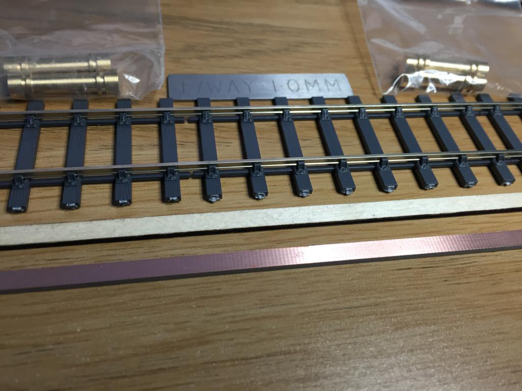
Im just building ( re building ) some test planks, in preparation for " Claremorris " next year. Ive been looking at C&L s new 00 flexi-track, which looked as if its based on its exactoscale fast track style bases. Its done in their new " HI-NI" high nickel content rail profile which they claim is more " white" then the typical " yellow" nickel sliver you sometimes see. ( I remain to be convinced ) . Note the good definition on the chairs due to newer moulds Hence its a full thickness track base ( 1.5 mm ) as opposed to their existing thin sleeper flex, Sleepers are 32mm long and 3.6mm wide ( 10 ") , which is the typical compromise C&L do for 00, spacing is at 10.3mm i.e. 2'6" which is fairly prototypical . Note that each track base is made up of an 8 sleeper panel connected by webs , which will have to be cut for curves. But the panel webs aid straight track deployment also the way the panel ends allows you to close up sleeper spacings at fishplates, but I dont think that was done in ireland as a lot of bullhead followed american practice post war, and had staggered joints ( comments ?) I'm ( fairly ) sure all the light weight FB track was staggered Some issues are the flash on the sleeper ends, and of course its a three bolt chair that wasn't used that much in ireland I also include by comparison , my current stock of prototype 14" wide ply and 12" wide copper clad turnout timbers, all nominally 1.5mm thickness, hence to line up the rail heads the rail will have to be lifted about 0.6mm from the sleeper. This is of course a major failing of PECO track in trying to represent bullhead rail. You can also see left from top left to right the new 00-SF gauges, track gauge ( 16.2mm) , crossing flange way 1mm shim and 15.2mm check rail gauge , my own view is the specs for these gauges make them very physical small but how in ever I also include a pic of C&L 4 bolt plain chair and slide chair , while not identical to GSWR/CIE chairs , they are at least a reasonable approximation note , annoying c&L have locator pips on the slide chairs , which always bugs me. not so on the plain chairs . The moulds for these chairs are now quite old and the definition is a little lacking my preferred method of construction is ( was) copper clad, with vero pins raising the track up 0.6mm and then applying plain and slide chairs cosmetically ( half chairs) , chopping up plain chairs as required to simulate more specialist crossing chairs etc. My test track however , will be built with a combination of functional chairs on ply with crossing, switch and closure rails on the turnouts strengthened by either ply and rivet ( or ply and vero pin) or copper clad and vero pin, copper clad strips are now so expensive that major use of them is prohibitive All the station track work will be retained at 00-SF 16.2mm ( 1mm flange way gap) flaring out in scenic sections to c&L flexi at 16.5mm, no radius in under 3' so gauge widening is not required. The 16.2mm gauge in the station area, greatly aids shunting and propelling . It further allows both RP25/110 wheel types and also everything short of S4 and US P87 wheels to be properly supported while running through the common crossing I will also be using code 55 flat-bottomed rail to represent the lighter laid sidings in claremorris and ballinrobe , I havent seen a good method of representing Irish FB chairs of the period, so at present this will be just soldered onto copper clad. It might be worth doing a custom etched fret to try and simulate the peculiar low chair that was common ( and is still there today ) but we'll see. currently I notice that the only code 55 FB rail is in steel , Ive no experience of steel rails , anyone seen code 55 FB in nickel silver ?. ( mind you steel does have advantages ) Over the next two months , Ill try and describe my various building methods and experiments in this area. I have several ideas to try out including CNC machined switch blades , new servo based turnout operating units , fibreglass PCB based stretcher/tiebars stay tuned Dave

-
Prototype operation of models & layout design
Junctionmad replied to David Holman's topic in General Chat
actually no they weren't . what they had was a series of movements that repeated over days weeks, months and years and hence became common place. to the casual observer , it looked like a puzzle being solved on the spot, to the railwaymen, it was simply what they did yesterday as well. -
Prototype operation of models & layout design
Junctionmad replied to David Holman's topic in General Chat
I agree with Davids ( OP) post entirely, In Ireland especially we are rapidly loosing the race memory of how a loco hauled freight orientated network operated, far quicker then in the UK. We are also loosing things like correct semaphore signalling protocols and operation, How many times do you see a proper signalled irish layout operated correctly. yet we have lost in the last ten years a huge amount of prototype situations, even in the UK quite large semaphore setups for example still exist For those that believe they are " modelling railways " and not trains , it behooves us to try and operate our layouts as close as we can to real prototype operations, especially for nut jobs like me that tend to focus on a real station during a fairly narrow time period ( with some modellers license of course) I hate " exhibition layouts " build to just run roundy roundy trains on the basis of " simple things for simple folk". its the ultimate fob off for railway modellers. I see these increasing at irish events and Im not happy !. People need to study WTTs etc and build " layout time table tables: or at least a sequence of written down operations, in the prototype basically everything a loco did was timetabled and scheduled. The more we emulate the prototype the more we retain the race memory for example shunting loose couple ( or fitted freight) was not a random series of shunts, trains had to be built, under the control of the guard . to minimise further shunting along the route. Goods trains didn't in general randomly set off around the country , they were carefully time tabled and " pathed" MY own layout will be capable of being exhibited,in that the layout is " portable " albeit , it will take up a fair space , but whether I will or not is another question. To operate a layout like " Claremorris & Ballinrobe " with a regular train movement schedule, on a fully signalled layout tends to require several skilled operators, who actually understand how the prototype was operated , this is my experience is difficult to find On a final point , Noel, in real life shunting was a " job" and one that had to be completed in typical irish conditions like p!ssing rain etc, No-one hung around and these locos tended to push stock at well above walking speeds , engine run rounds etc were often at 15mph . I think any large layout , operated to its potential , particularly at an exhibition, , needs a "layout" timetable , other wise you just get chaos Dave -
There is curtain rail designed for boats and caravans that is about 6-8 mm c section. Personally I'd just route out a Channel in the timber and use the strips of self adhesive LEDs.
-
I use trax3 , any rail , I find trac3 easier to use. Runs under parallels n a Mac. Both my Limerick junction and claremorris layouts were initially designed in it. The only drawback of these programs is they restrict you to set track configurations. Ultimately I put the whole things into Templot as its the only program I believe in regards dimensional accuracy Using a pencil for layout design is a bad idea as you are always inclined to squeeze turnouts and radius into spaces that When using a proper design tool, turn out to be impossible. A case of wishful thinking. Dave
-
Complex track work is an anathema to modern rail companies and especially IE. Modern tamping machines. Etc also dictate the use of simple track work and modern turnouts are pre fabricated virtually like hornby set track. The bridge was singled in the 1920s when the centre arch was replaced. I presume that the signalling merely treated guantletted track as n a similar way to the current arrangement, with a one train in section approach
-
The term guard rails and check rails are interchangeable , with " guard" rail being primarily US rail terminology.
-
Love the video , but that signal omg. !! I would not build a roundy roundy in 3ft wide baseboards. Way too confining a radius. Do a terminus or even a through station with sector plates at each end
-
What was the story behind cies palvans, where they a post 1970s freight modernisation idea. ?
-
I'm am so looking forward to start track laying on this layout next year. It's a fascinating station. Who needs a fiddle yard when you can justify putting trains everywhere. !!!!
-
Yes that's exactly the advantage
-
2 x Mk4 sets leaving Heuston
Junctionmad replied to Noel's topic in What's happening on the network?
I agree with Noel , being a big lad, the seating on the ICR is AWFUL , sore ar$e after an hour. The sa,me nonsense jseating is visited on us, in modern darts And Dublin bus. No seat springing., just a sort thin foam pad and " indvidual " seat shapes designed to accommodate midgets Give me the big bench of a Park Royal or laminate any day, nice sprung seats and tall backs. Heaven. Remember the days when you could spread across a bench designed to sit three and comfortably snooze the journey away to the huge excessive steam heating to your feet while a gale Blew around your heads from the open windows ! Ah bliss I agree with others re air con. I remember being on the first mk2s , I was disgusted to find the Windows didn't open. ( at least you could hang out the door Windows ) [ranton] When you build a rail system solely around saving money , you end up with this type of nonsense [/rantoff] -
It looked more like a check rail , then gauntlet track work. That's why I asked.
-
That lighting has all the taste of a seaside arcade By the way , is the track work still gaunt, or now conventional
-
Limerick Junction track layout/ signalling plan 1975-85
Junctionmad replied to Junctionmad's question in Questions & Answers
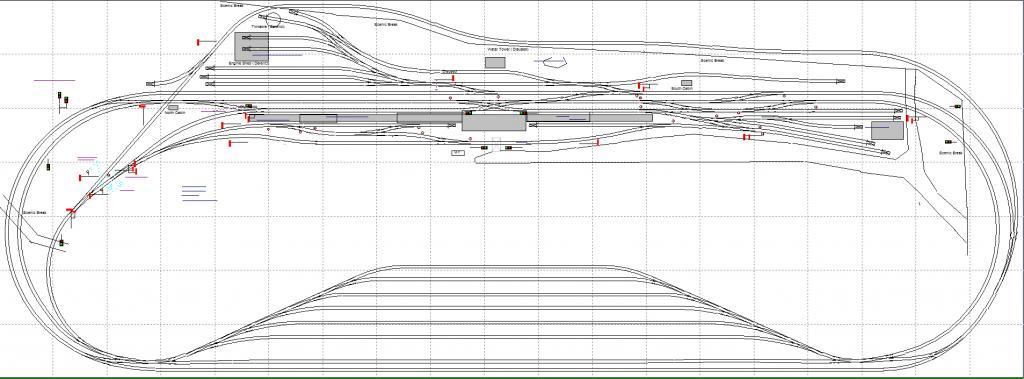
heres my interpretation of LJ that I decided not to proceed with, the curves are too to tight for the space and it needed 20 feet
-
Limerick Junction track layout/ signalling plan 1975-85
Junctionmad replied to Junctionmad's question in Questions & Answers
well places like waterford were even busier, but waterford is effectively "un-modelable" given the overall length -
Limerick Junction track layout/ signalling plan 1975-85
Junctionmad replied to Junctionmad's question in Questions & Answers
sure. I have another visit booked there in January to speak with Dolores and talk to a few auld buffers!.. I also have to bring my measuring stick as I forgot it the last time , duh Im on a quest to understand what happened to the men toilet roof !. ( Ill be the wierdo looking up ) Ill publish all the cad here, everything for the community -
Yes I suspecta trial is useful in model form its easier to drive two axles together , so BO-BO or AA1 rather then A1A , thats what I will be doing for DCC I prefer mashima indeed, but a plastic worm held in a gearbox is not a bad alternative and you get great reduction sorry slip of keyboard I meant USA P87 , which is their P4 yes, I was referring to the GM wheels gears are a bit behind me as yet. simple turning and boring, and I have no index table anyway
-
Southern Yard, brill photos , if you have any more I would be delighted , engines sand trains stuck up every siding I wonder what they did when the burma and ennis lines were in service any dates on those photos , looks early 80s ? latex 70s, it was before the lowered the platform starter i see
-
As I mentioned , I'm working on a similar idea for my Sulzer model. I currently just finished the gearbox and frame CAD so I can use my proxxon MF 50 CNC milling machine to mill out. I will be trying the " Varney " derivative of continuous sprung beam suspension , which produces an adjustable suspension system. I'm still not sure about secondary Springing of the bolster , I wonder if it's needed. Obviously track undulations over the length of the loco could exceed the 1mm total springing travel available added across both bogies ( each horn block has +- .5 mm travel ) , this would cause wheel lift. I'm going to try split axle power collection, hence a dead frame. Failing that, the fall back is live alternative bogies, which is typically what the US models use. , I'd be very interested in your experience with the penbit chassis I'm plan to do the gearbox in delrin with a plastic two stage gear wheels with a final worm , and then carden shafts to the motor ( I'm waiting for DCC concepts ball joints to arrive ) What are you gong to use to motorised the penbits bogies/ chassis. As an aside. I've noticed it's very difficult to source 40 " diesel driving wheels from UK sources as it was never used on their locos. ( even on class 68 etc ) but. Just realised that H0 (3.5mm ) 45 " wheels scale almost perfectly to 40" in 4mm , there are available from NSWL in the US and I've ordered a dozen for future projects ( spung 121 141 bogies ! ). These are 25/110 profiles so way too coarse for p4. They are also available in code 88 which is close to p4 , ( n fact a little finer then p4 ) If it's successful, I may offer it as a kit to interested parties. ( some assembly required, batteries not included ). The idea would be to do ABC class bogies first. Delrin gearbox, delrin hornblocks, with brass bushes. , brass frames. , ultimately I could convert most of the brass into etched components. It's all in the minds eye at present. The gearbox will be roughed out over Christmas break, assuming my rebuild of the Cnc controller gets finished My Seig lathe is coming n the new year so that will help ( I delayed my iPad pro purchase instead !!!! )
-
I'll begin to post track construction workbenches in the new year. Progress will be slow !
-
Wouldn't it just , they must of hidden them up trees. ( well actually they just pushed them all up the ballinrobe branch. Basically they used every piece of track possible. Then they reassembled all the trains again for the return journey in the evening ( they were on Sunday's usually ) 9-10 carraige trains came from everywhere in Ireland , msny using the limerick line even when it no longer supported timetabled traffic. Trains would come from all major railhead towns across the country, often arriving within minutes of one another.