.png.c363cdf5c3fb7955cd92a55eb6dbbae0.png)


Paul 34F
-
Posts
102 -
Joined
-
Last visited
Paul 34F's Achievements






-
Lovely photo. Middle top is the old Loco shed, before Adelaide opened. A very interesting mixture of rolling stock with useful roof details for six wheelers. Paul
-
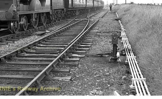
David, I took a closer look at the Ground Signal, you mentioned. It is not operated from the point stretcher bar, instead the rodding operates the slide detector, in association with the stretcher bar, which automatically controls if the Ground Signal can be cleared or not. (The slide detector confirms the switch rail is in the reverse position on the point.) The signal operating wire can be seen coming from under the counter weight and heading towards the photographer. Paul

-
National Museum of Ireland, railway collection
Paul 34F replied to cheesy_peas's topic in General Chat
Just had a look. Discovered a GA diagram for Sprite, the tiny 0-4-0t and attached pay carriage. The interior of the carriage is shown. One for Mr Holman Paul -
Dear All, The following link appeared in my YouTube feed a few days ago. It is the debate in the Northern Ireland, on the proposals to close the lines in the west and featuring other sections already closed. Some interesting footage on the NCC, BCDR, CDRJC (Derry-Strabane), GNRI and the SLNCR. Enjoy https://youtu.be/Xz0s7C7oq-M?is=sEA7W_OEEF7kJkKP Paul
- 2 replies
-
- 1
-

-
- northern ireland
- rail bus
- (and 6 more)
-
Interesting to note the K15 at Bundoran with Belfast - Dublin carriage boards. Paul
-
A certain scene with Father Ted comes to mind! Paul
-
This device could useful at exhibitions to get rid of those less Savoury Characters, that have a habit of visiting shows. Just got to remember to deploy a more pleasant smell to attract the general crowd back to the layout, afterwards!!!!! Paul
-
Leslie, I had a look at the link. It’s wonderful to see it as it now is. It’s 69 years since the last train passed! Paul
-
My personal view is, the original junction was double track. The bridge was constructed for double track and what became the siding, opposite the Bundoran platform, actually terminated under the bridge. I wonder if there was a platform under the vegetation adjacent the siding? The arrangement is an example of cost cutting. The service demands don’t require a double junction and the simple solution is the removal of one point, moving a facing point lock, and adding a buffer stop. The result, trains to Bundoran from Enniskillen diverge right to then go left. Which to those unaware of the actual situation will look very odd! Paul
-
A wonderful shot of Bundoran Junction. It would make an interesting layout, due to the arrangement accessing the Bundoran line, plus the associated shunting and splitting of trains. Paul
-
David, Hope your house move goes smoothly. I’m still plodding along with the U class drawings. Summer maintenance is taking up all of my time at the moment. Paul
-
I can sympathise with Mol_PMB, I too was trained in the world of 2D drawing, (both hand drawing and early CAD systems) and have the ability to visualise 3D objects. It is a steep learning curve, however, I’m following tutorials on the internet and I’m able to recreate the item in the video. I have to rewatch the footage several times over, due to trying to keep up with the speed of the operator. Bullet_Wanderer, your recreation of a J26 is impressive. If you were to split it down further, consider separating the cab/bunker and probably the chimney. It would allow different versions to be created. One question, what wall thickness have you selected? Kind regards Paul
-
It has already dawned on me, there are two distinct paths to follow here, which represent most members of the railway modelling community. This affects how a vehicle should be produced. It is a reflection of the situation with white metal kits 60 odd years ago. So the two choices are, one piece complete body shells or a kit of parts to assemble. Either can be designed to suit RTR chassis or printed chassis can be provided. Whilst a one piece shell is attractive for those who feel they may not be able to assemble a kit, a set of parts maybe more practical to allow for variations within a class of vehicle. The latter would dependent on the quality of the design and the tolerances of the printer used. As Rob has shown, not everything already available is correct. This is a reflection on the Designer and what this person believes is correct. As for the time required to print, it seems slow, but I appreciate, you can go off and do something else. The newest printers have a built in camera, so you can always keep an eye on the process via a smartphone. I have pondered whether you could print off a set of masters to make a mould, or you could just print a mould and cast items from this. The options and possibilities seem endless. I really need to get some equipment and give it a try. Paul
-
I’m sure George Glover would have known Gresley. Most Locomotive Engineers were members of one Institute or another. Paul
-
With regard to acquiring the Artwork from Allen. The drawings for the photo tools were in a digital format over 20 years ago. He produced the digital diagrams for the CDRJC Class 5 in 15mm scale from my original hand drawn effort. Paul