KMCE
-
Posts
540 -
Joined
-
Last visited
-
Days Won
29
Content Type
Profiles
Forums
Resource Library
Events
Gallery
Blogs
Store
Community Map
Everything posted by KMCE
-
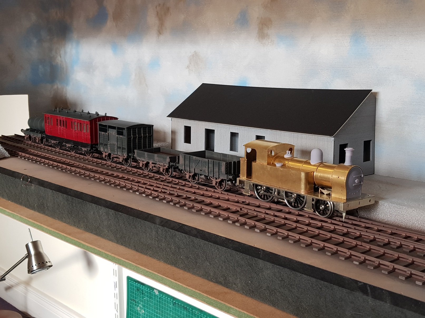
Got some painting done on the wagons. I think in need to tone down the Cattle Brake as it's a bit glossy - perhaps a little matt varnish would help. A touch of bleed through with the black on the corner, but that should clean up easily - the body paint is tough paint (rattle can RAL 3004). Lettering and numbering to follow, but quite pleased how they have turned out. They do take quite a bit of paint given the size - will need to order some more air brush paint! And an overall view; DSER branch train with loco..... Anyway, all for now, and for those going, I'll have this on display in Bray. Ken

- 379 replies
-
- 12
-

-
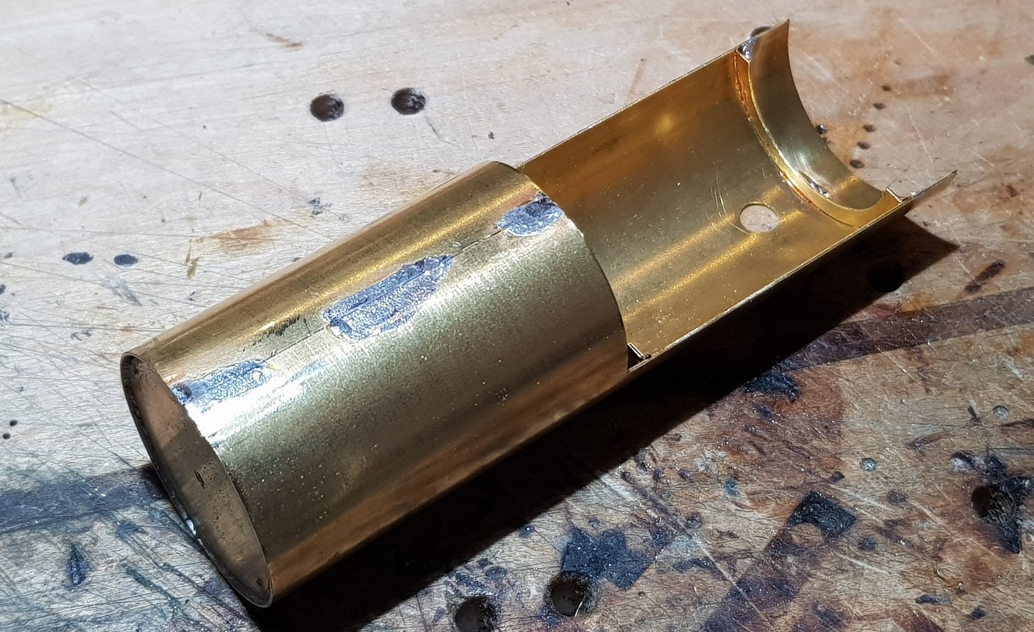
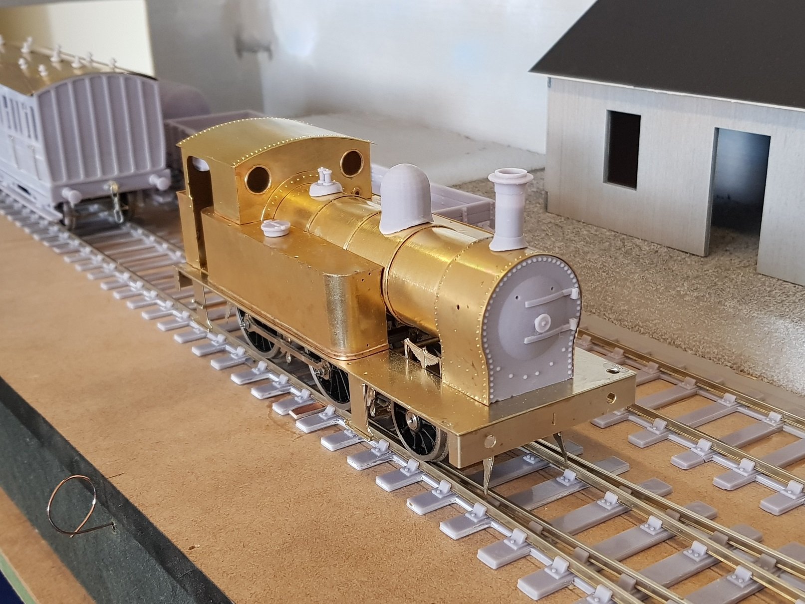
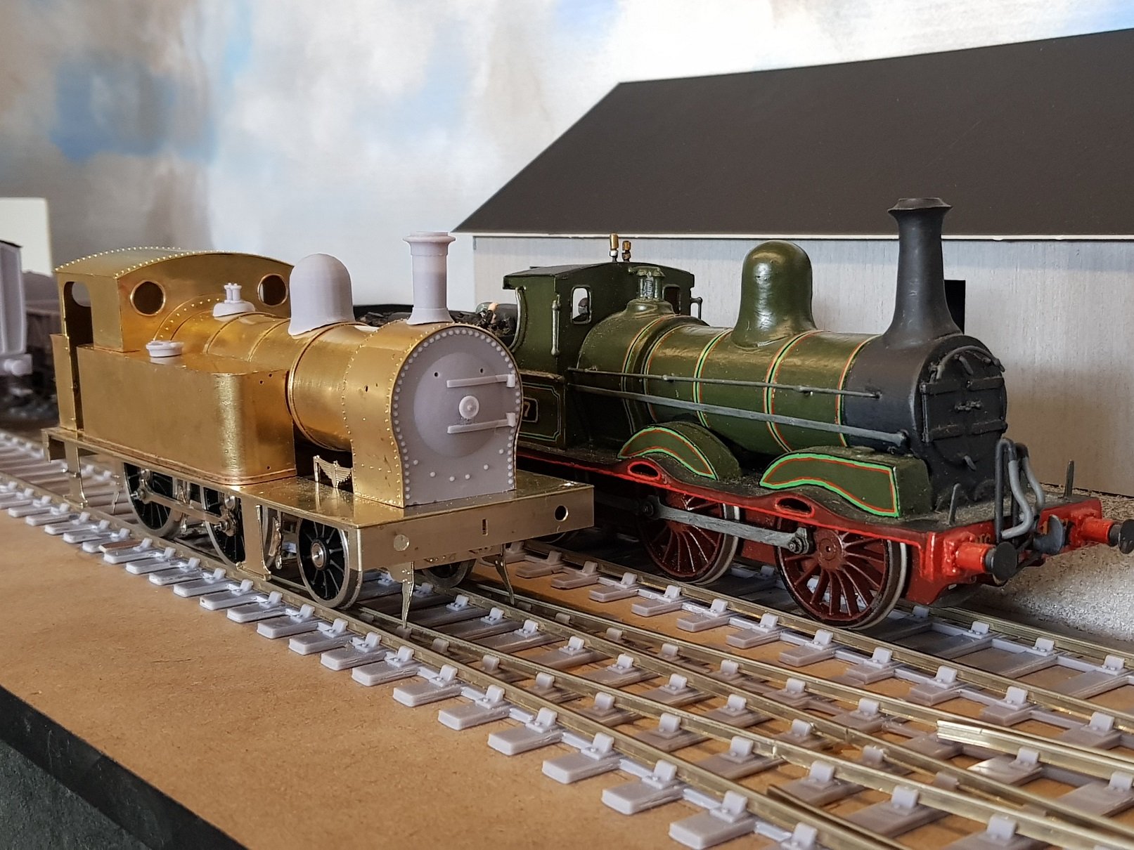
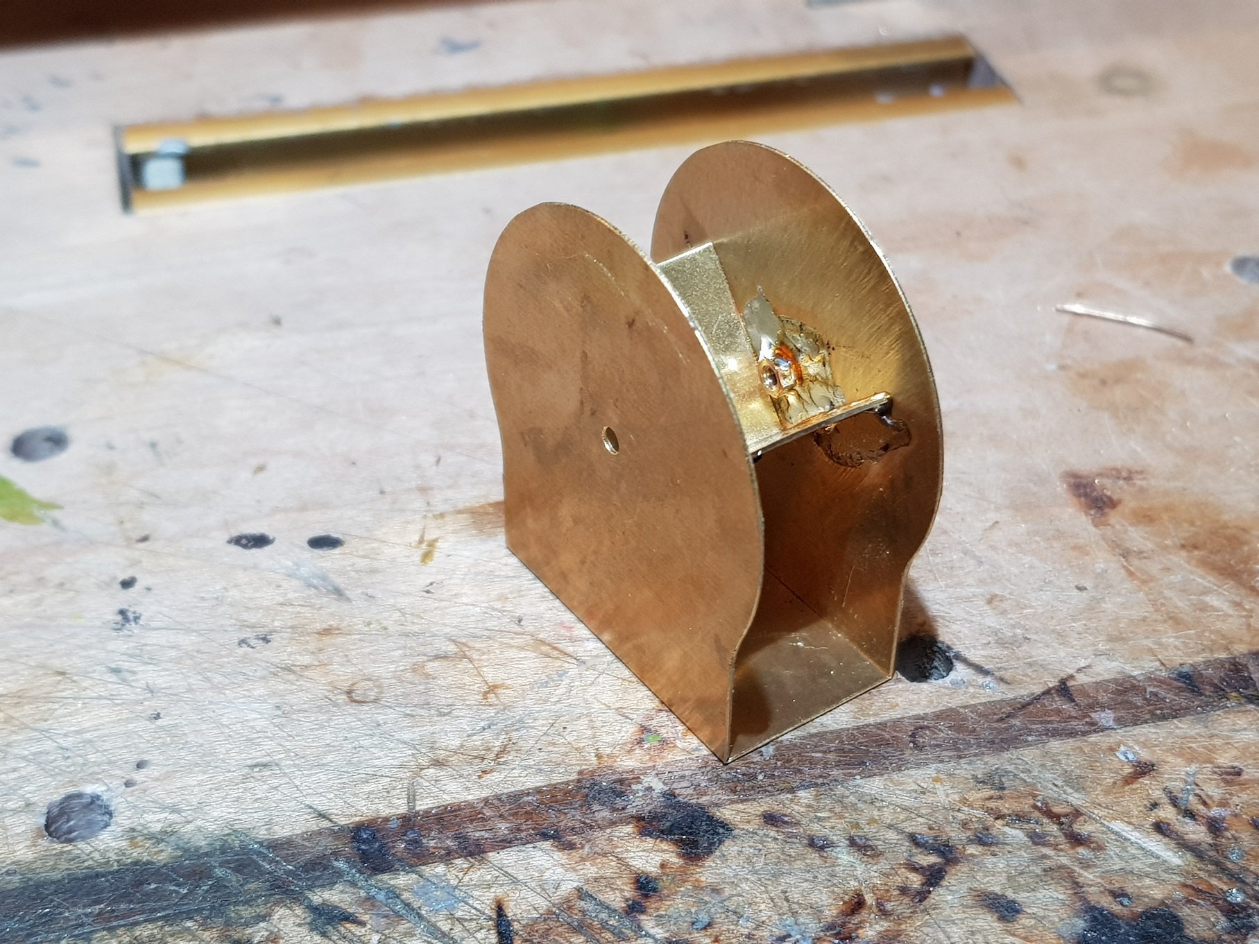
Following on from the last work, the next phase was boiler and smoke box. Me being me, I once again forgot to take interim pictures - once I get focused on an element, I forget to take photos. What I have got does show the smoke box former and boiler being formed, so I'll have to fill in the gaps with text. Boiler was rolled and the small semi-circular formers and front disc were used to get the shape correct. The etch was to include a forming ring in the Nickel Steel element which slips over the boiler and helps to keep the shape when soldering - this ring also is used as the first step down ring from the smokebox to the boiler, so serves two functions. Sadly this did not etch properly & so I had to make do with what I had. The two semi circular sections help to keep the cut away section to the correct shape - I find the rolling only will not get and keep the shape in this section, so these elements help to keep the shape, but leave clear space for any internal motor & gearbox arrangement. Boiler seam soldered up nicely, but dimension are probably 1mm out as there was a slight gap when fitting the disc; I can change this in the etch for the final version. Smokebox was up next and this was created in the usual fashion of a smokebox former with the outer wrapper sweated on. Alas, this is where the photos stopped. The smokebox wrapper needed to be annealed to soften it as the metal thickness was too much for immediate installation. The design is for the wrapper to sail past the former which creates a pocket to allow the installation of the 3D printed smokebox front. I found this method worked well on the other locos I built and followed the process here. Again some dimensioning issues here; smoke box wrapper was c. 2mm long while the former stands c. 1mm to low. The recess created is also a little too deep, so the smokebox front is packed out with some scrap brass from the fret to get things lining up again. To resolve the heights issues, the former is packed up with an off cut from the etch, while the bottom of the sides have been filed back to fit - not ideal, as this brings the rivets very close to the footplate. All these issues can be picked up during the final design pass for the kit - they are not major issues, but once found it will be good to get them sorted. I had not included any boiler bands in the kit, and not having any 1.5mm strip, I cut strips from spare brass in the kit & made up the bands - quite a bit of work & I think I'll include boiler bands in the etch to make it easier on the next builder. So, bringing it all together with some of the 3D printed parts we get: It has come together quite well even with the few kit issues. These were not major but the did add to the build time whilst workarounds were sought. Looking good so far, but that's the easy bit done - now for the tough bit......all the detailing. I find detailing can take almost as long as the basic build, and while it feels you a working for an age without progress, it does make the difference in developing the model. I'll probably pause the build for now, take a break and work on some other parts of the project. I took a photo of the loco next to @Northroader excellent J15 and was quite surprised at the size difference. I my mind I had always seen the 423 locos as small, but they are of considerable size next to the J15 - no wonder they were so capable and ran on the system almost to the end of steam. Nice comparison. Anyway, all for now. I'm off to work on some other bits for a change. More as time permits. Ken
- 379 replies
-
- 15
-
-

-
What I find helps is marking the the outline of the cab onto the roof with a felt pen when you're happy with the fit, then scribe in 1mm from that line. These lines act as guides to where to bend the wire & get a rough fit for the roof. You can just make out the scribe marks in the photo above. Ken
-
No problem. Quite simple in that there are only 4 wire springs, however the tricky bit is getting them sufficiently tensioned to keep the roof on and centralised. Hope that helps. Ken
-
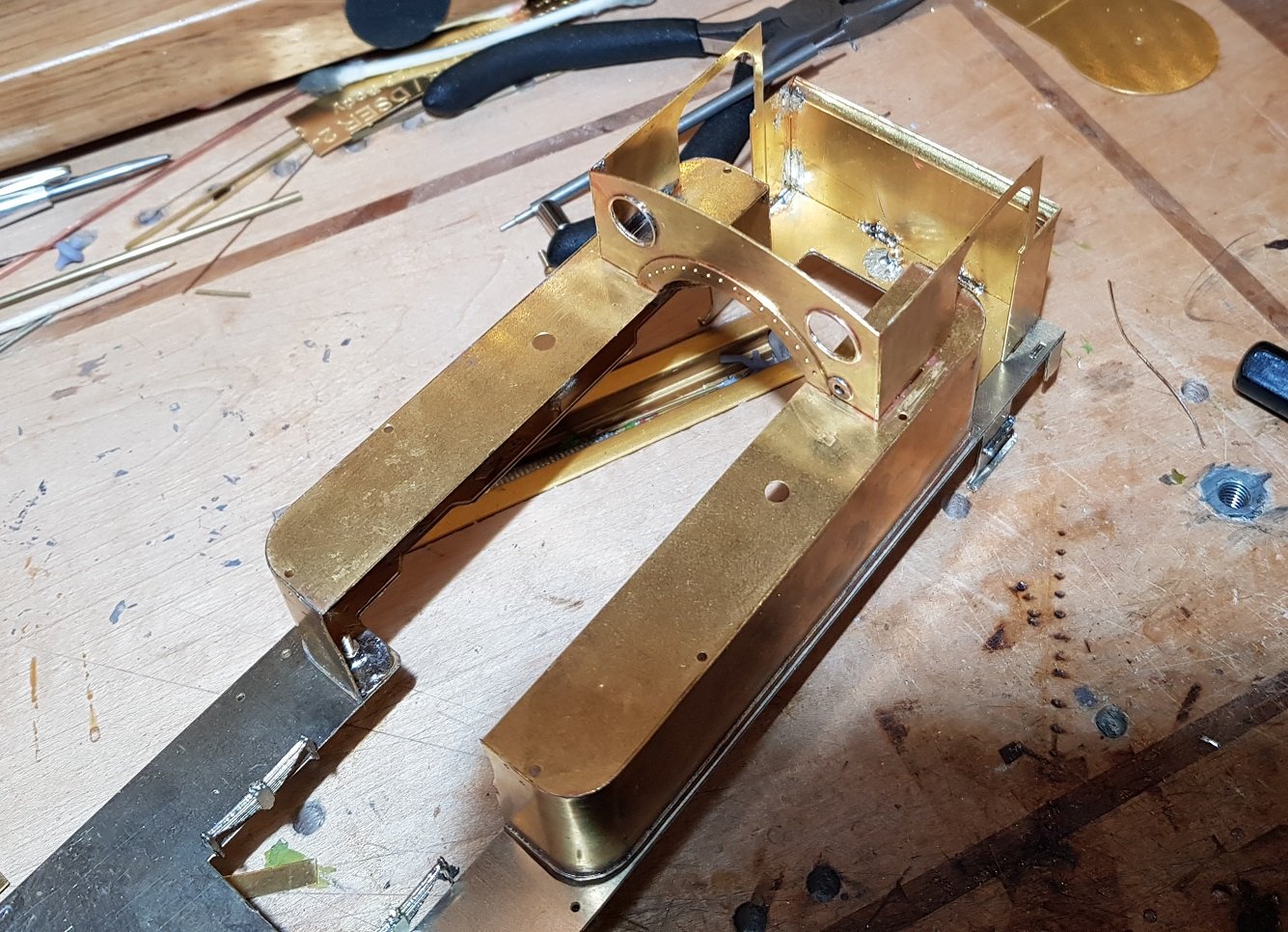
Moving along, cab is up next. Cab sides are mated to the bunker rear on the bench and then offered up to the lower tank former and tanks. Forgot to take photos as I was working, so most was assembled before I remembered to take any. Cab front was then dressed with the additional detail. One detail which did not make it through the etching process was the spectacle detail - outer ring was formed but the centre didn't etch out, so I had to use some half round brass to provide the detail. Fiddly to execute, but hopefully in the final kit version, this should only take minutes to sweat them on. These locos also had a distinctive riveted arch over the boiler which is allowed for. Rivets are half etched on the rear of the sheet and need pushing out; given the thickness of metal, I used the rivet punch to complete the job. Same issue with the cab rear for the spectacle plates, but once done the cab rear slides down the etched guides into place for a nice clean fit. Dimensioning of parts in the kit has worked out well for these elements and they have come together quite nicely. All that's left is to add the roof - in this instance I used phosphor bronze wire to create springs in the corners so the roof can be taken off should I want to do any internal detail. Back onto the chassis to get an overall look at how it's coming together. All for now. Ken
- 379 replies
-
- 14
-
-
-
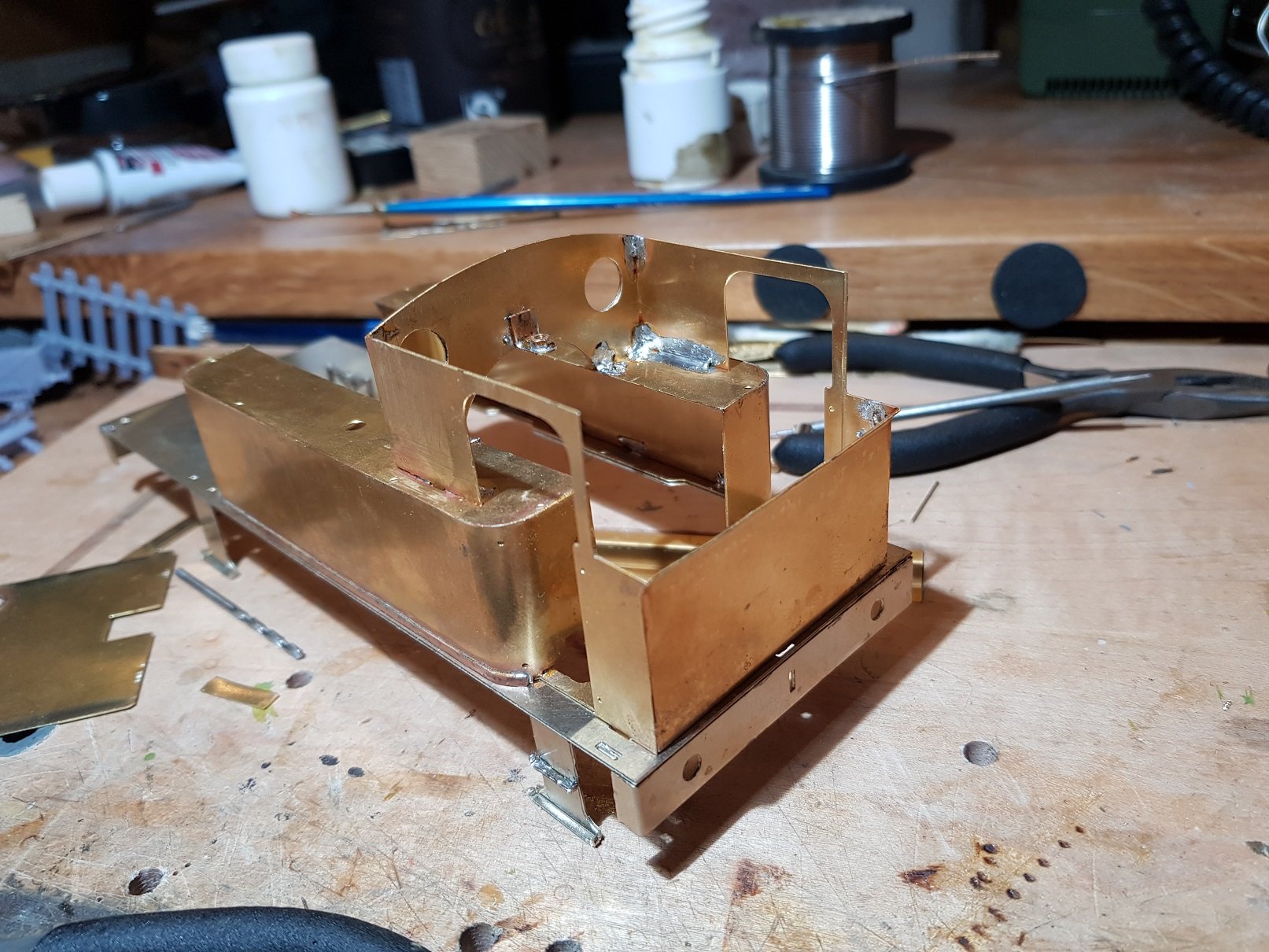
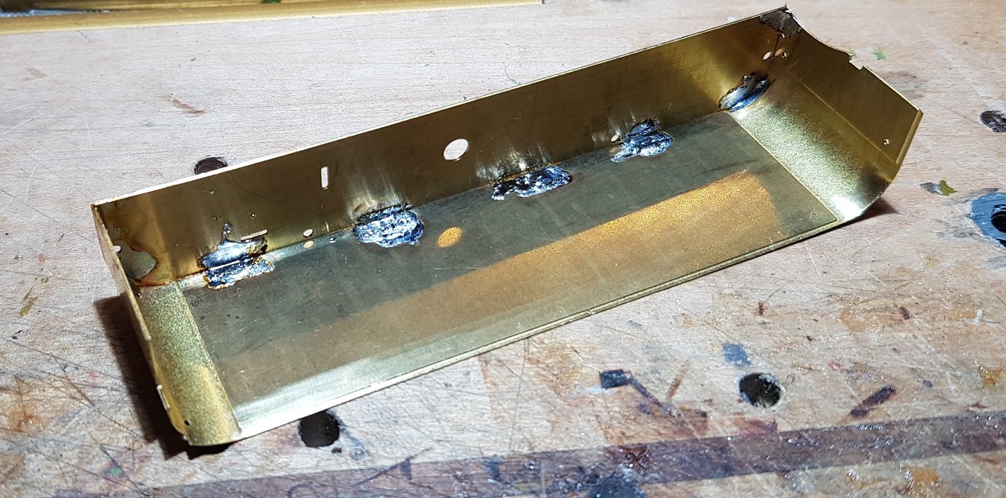
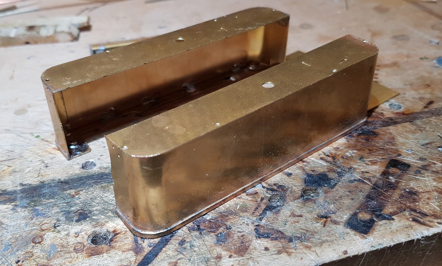
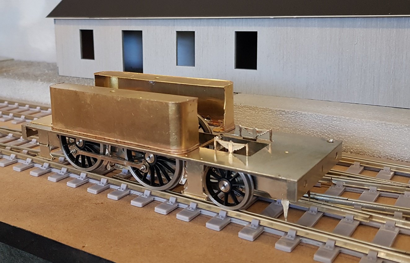
Back to the loco for a spell. Upper body is dominated by the tanks on these locos and they take some time to get right. The kit is designed with both a tank top and tank bottom formers to help form the sides with minimal distortion. Tank side wrapped around the top former. Then fixed to the lower former to help fix the shape. The lower tank former also acts as a means to hold the body down on the chassis, so captive nuts soldered in place. Second tank side added. This kit needed a separate lower trim detail - in the P4 version this detail is part of the side and back folded up. Metal at 7mm is too thick which would have made the corners very difficult to form, so a separate strip provided which is sweated into place. And tanks on the chassis for context. Whilst visually and descriptively this does not appear to be much work, I can assure there is a lot to it, and one of those jobs I'm glad to get done. Can move on with cab and boiler next. Anyway, all for now. More as time and energy permits. Ken
- 379 replies
-
- 14
-
-

-
-
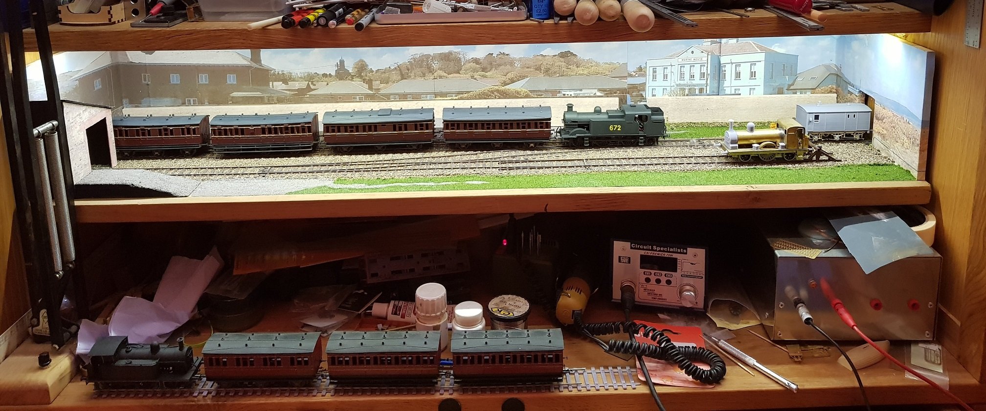
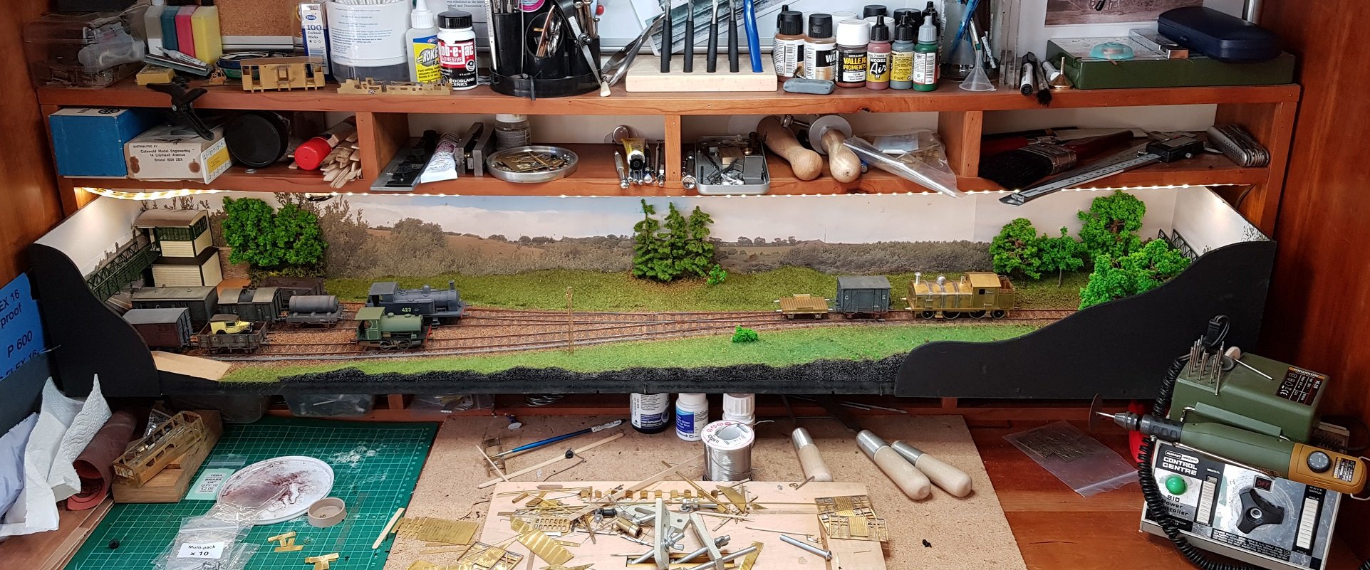
I find test tracks to be useful, and have built one for my work areas. They provide a nice backdrop for running, photos, and just appreciate work done to date. First one was built for my old work area and has subsequently been incorporated into the Coat's Bridge layout. Many models ran for the first time on this layout and photos posted here at the time. When I built my current workspace, the layout above was too big to fit into the space available so a new mini layout was built. This one represents a section of the Murrough Station looking from the sea side. Not hugely developed in scenic terms & I had intended to put in some trees etc - still waiting for that to happen! Ah maybe one day. I'm not in a position to put in a shuttle system as my models are all RC, so unless I sit there with the controllers, they aren't going anywhere. Still nice to see them when you are working away, although, it can remind you of what you haven't completed.... Well worth doing if you have the space.
- 10 replies
-
- 17
-
-
You can't beat a small pot!!
-
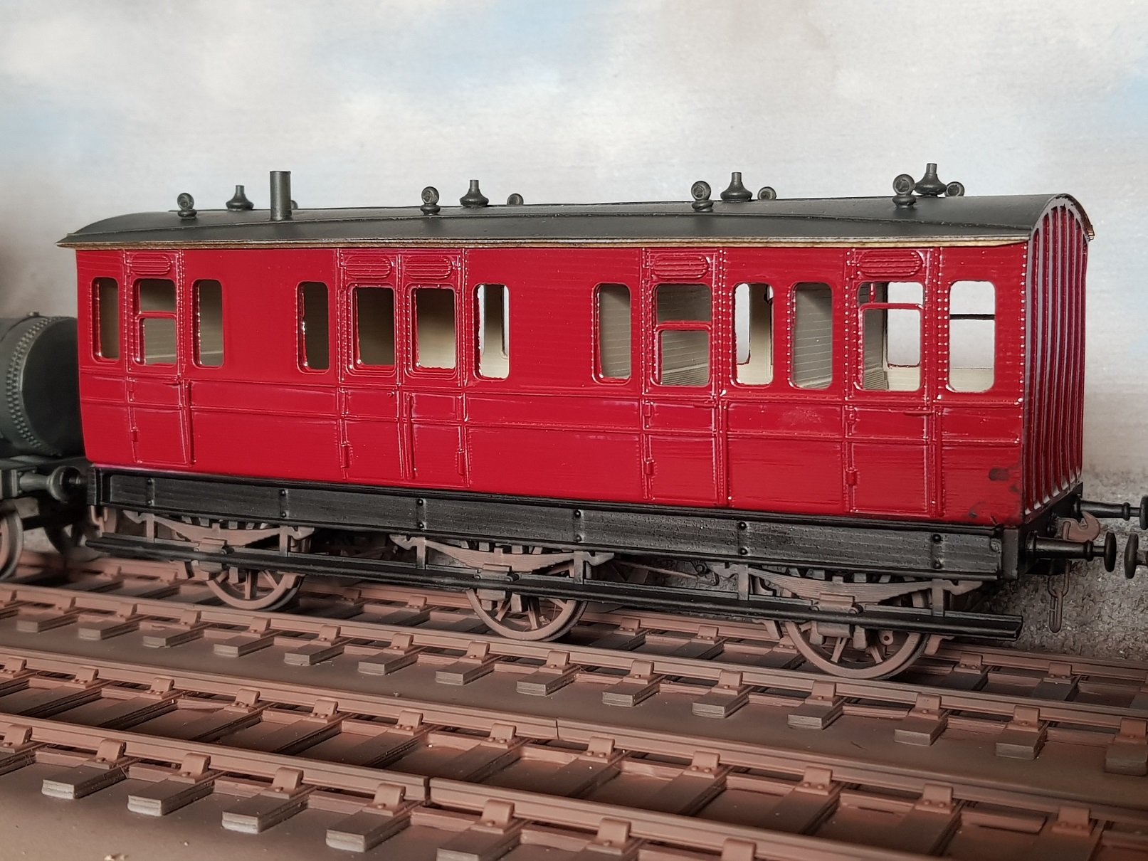
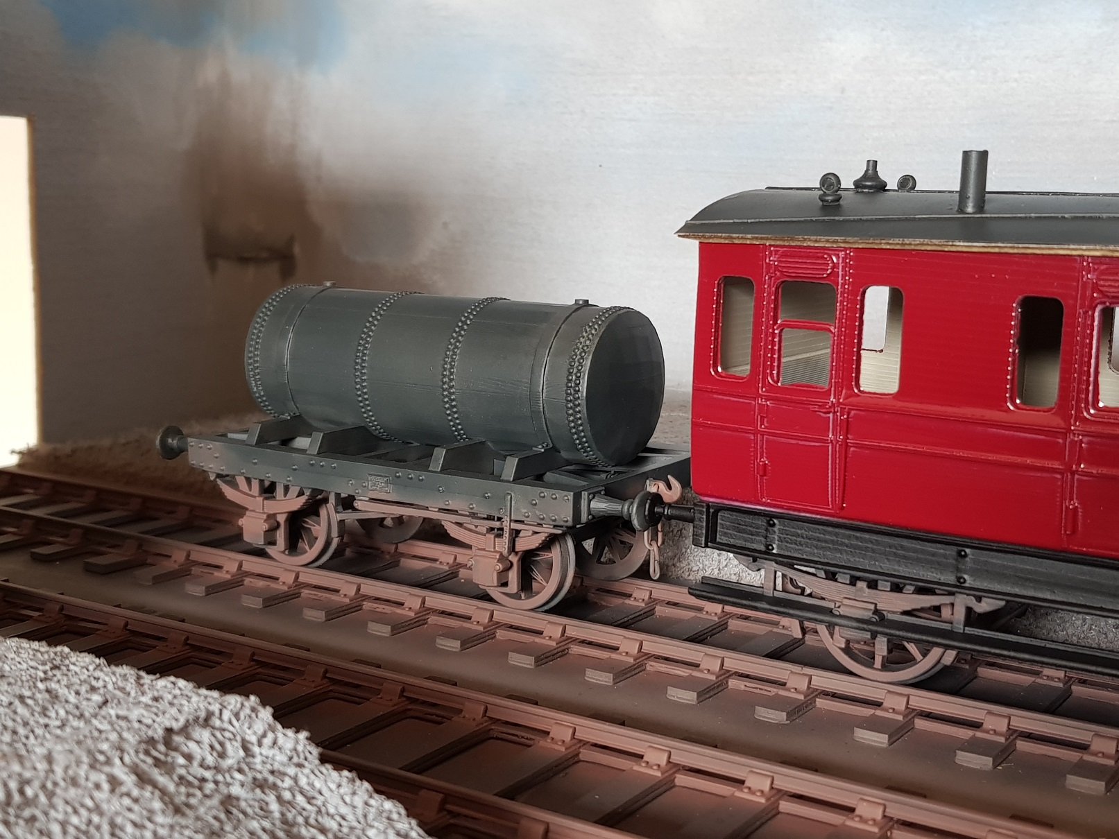
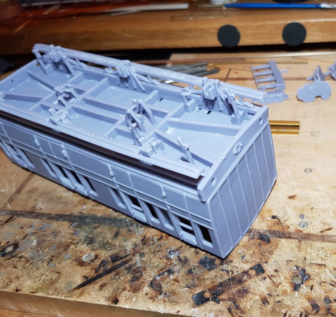
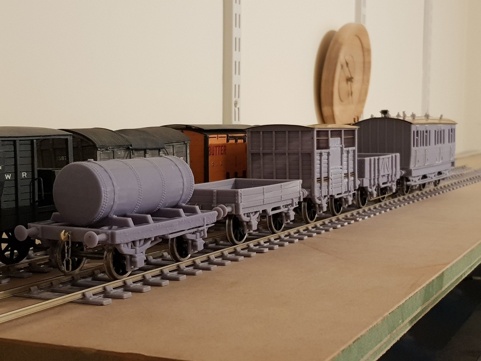
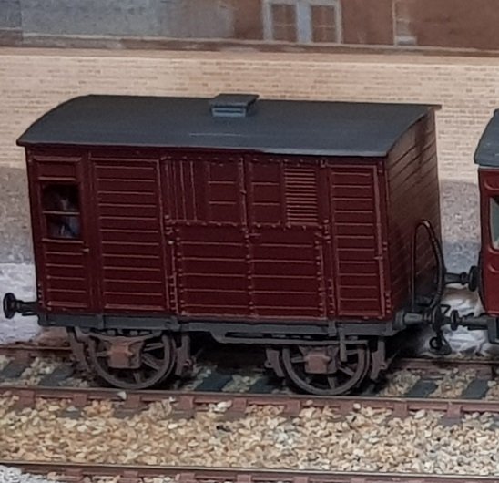
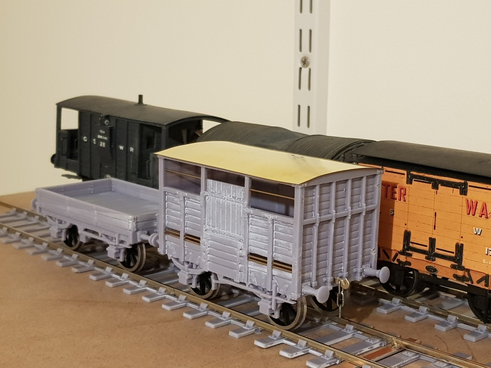
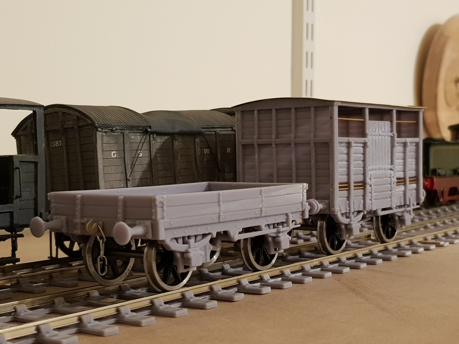
Wagon production has continued and given I needed a brake van or similar for the train, I decided to upscale the Cattle Brake. The thought process is to paint this in un-lined coach colour with number and class lettering on the doors - the cattle brakes were initially part of the coaching stock and were only transferred to the wagon stock post 1913, so coach livery will bring a bit of colour to the train. The model was tweaked to make it more accurate for 7mm. The coach without buffers just barely fit on the build plate of the printer which led to its own problems. Not all 3D printing goes to plan, and the supports for the end of the coach were compromised given the size which caused some sagging in the buffer beam. This was replaced by printing a new beam cutting out the misprinted part. Other issues were misprinted brake hangers and some problems with the axleboxes - again some re-printed parts were substituted to make good the problems. Brake hangars have always proved to be a problem with 3D printing as they are quite fragile and prone to breakage so I decided to cut some brass re-inforcing strips which were epoxied to the inside of the hangars which then allowed brake rigging to be installed. The bake rigging is removable which will help with painting and access to wheels as necessary. Following the underbody works, attention turned to the roof and body. I decided to use brass for the roof with 3D printed gas lamps and louvres - this allowed installation of rainstrips and gas pipework by soldering on some brass wire. A chimney was also added to keep the guard warm, but this needs to be tweaked as it's a bit askew. Door handles and grab handles added - I figured as this was a goods type brake, there is a greater chance of drovers and guard climbing aboard from ground level rather that platform, so a longer grab handles was added. This is my interpretation of a cattle brake - sadly no photos and very little information remains, so this is a result of much information gathering and interpolation of other coaches being constructed around the same time. Hopefully it's a reasonable representation. Another wagon added was the early 3-plank mineral wagon from the 1860's. Again this model was tweaked for 7mm and I also updated the buffers to the original style more in keeping with these early wagons. To close out the train I tweaked the gas tank to accept the 3 hook coupling so it can run with the other wagons. All for now - more as time and energy permits. Ken
- 379 replies
-
- 21
-
-
-
That locomotive has real presence and looks well in-situ; when seen with other stock and on the rails, it gives an indication of how big it was for a narrow gauge loco. Lovely project! The sequence of photos from image, to sheet, to wagon is impressive, and does have a "ta-da" feel to it. As to the couplings, I rather like the idea of the barrier wagon - the S&W couplings I use are handed, so you end up in bind if you turn the loco, as you said "Cunning plan Baldrick!"
-
That's a damn fine project - nicely done! I feel your pain with the rods, I've been there many times - I'm sure someone somewhere will create a tee shirt for it....
-
Superb! And knowing the work that went into it, there is great sense of achievement getting to the painting stage. Well done, Sir.
-
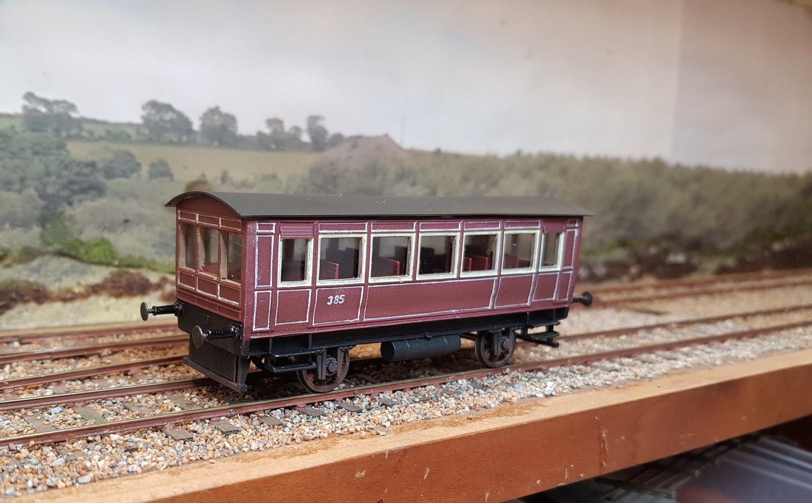
Worsley Works do an etch for the narrow gauge version of the railcar, however you only really get the sides and ends and is not really up to developing into the broad gauge version, I did my best but eventually gave up. I did want a model of the railcar though, so decided to go down the 3D printed route. It was reasonably successful, however these are quite small railcars, the prototype coming in at 23' 6" over headstocks & to put that in context, the DSER 6-wheel goods brake van is 20' over headstock. Being mainly windows and seats they don't lend themselves well for motorisation. This one runs with a 3V motor, High Level Gearbox, RC decoder & a small LIPO battery - given the wheels are only 10mm, it gives an idea of the limited space. Never got round to finishing the brakes though!! Ken
- 16 replies
-
- 10
-
-
Hello MauricJ, Great photo and I would agree that they are two horse boxes, however they are different from the model I have researched thus far. Photos of DWWR / DSER horseboxes are rare despite the RDS sidings clearly on the network and one would expect more photos given its popularity. The NLI photo is excellent and is from the DWWR period as the logos are visible on the semi and mineral wagons - It could also be dated by the oil lamps on the coaches, which means it predates 1885. If the published date of 1865 is to be believed, this was taken not long after the line was opened - the line didn't open to Shillelagh until May 1965. It could be that early as the goods shed has not been built yet (not sure when it was), however the open mineral wagon looks like the 1872 wagon built for carriage of copper ore from the Avoca mines, so perhaps a little later Loco looks like a 2-2-2 WT or a very early 2-4-0T (pity the wall is in the way), but good information nonetheless. Thanks for posting. Ken
-
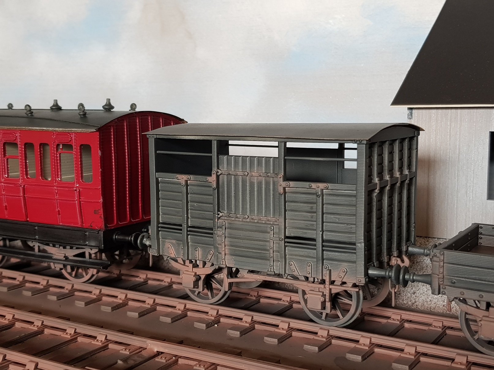
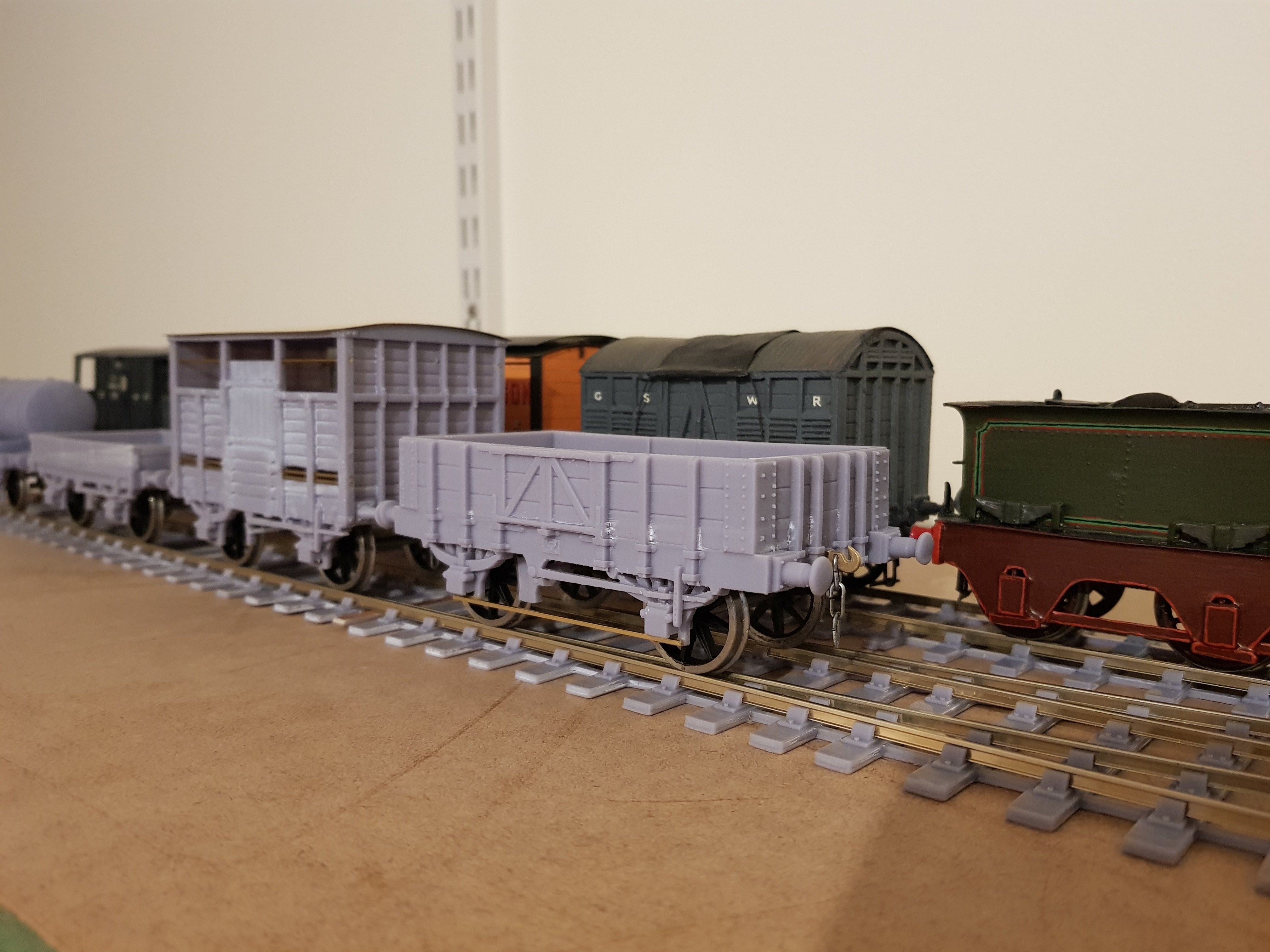
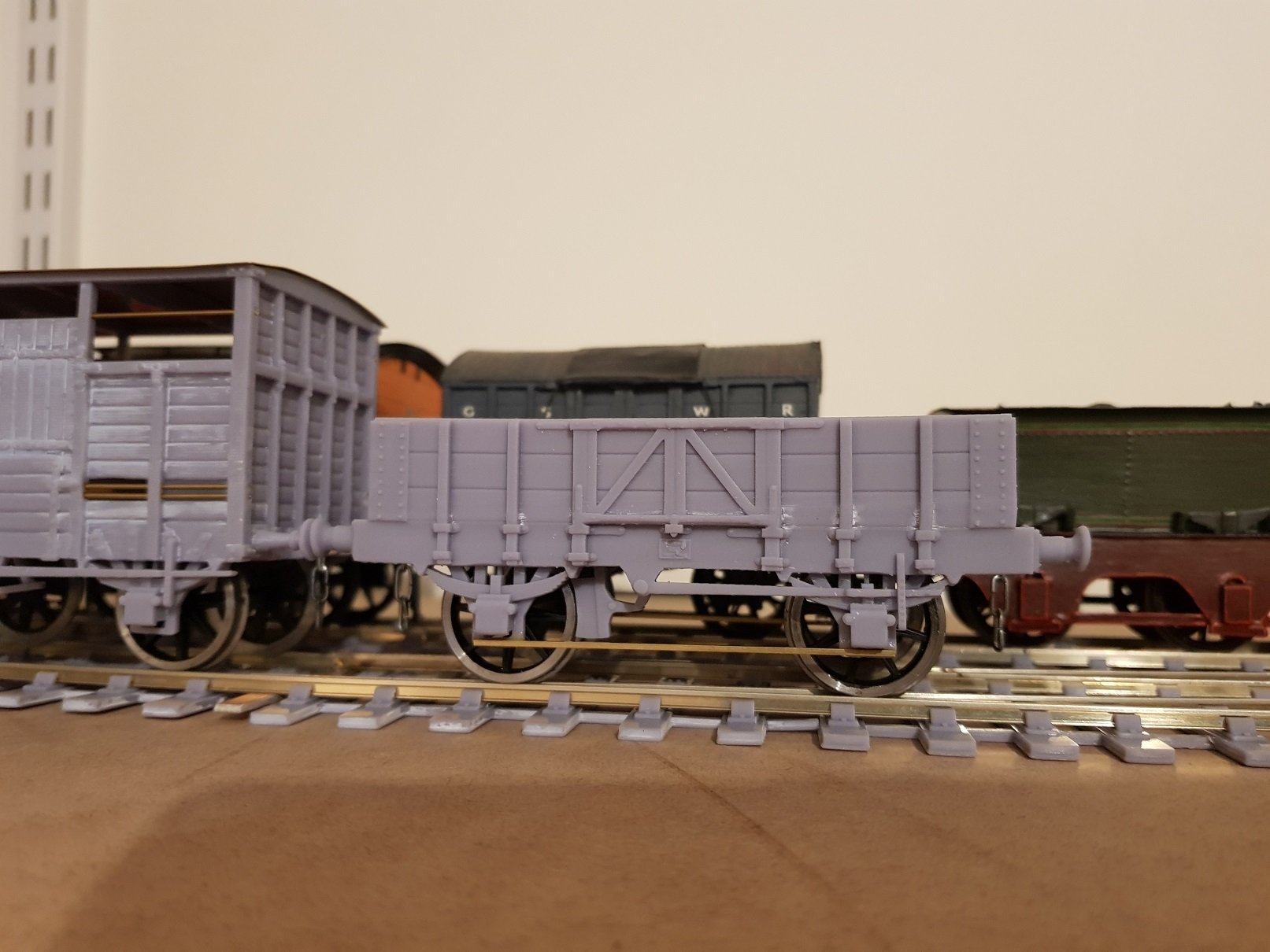
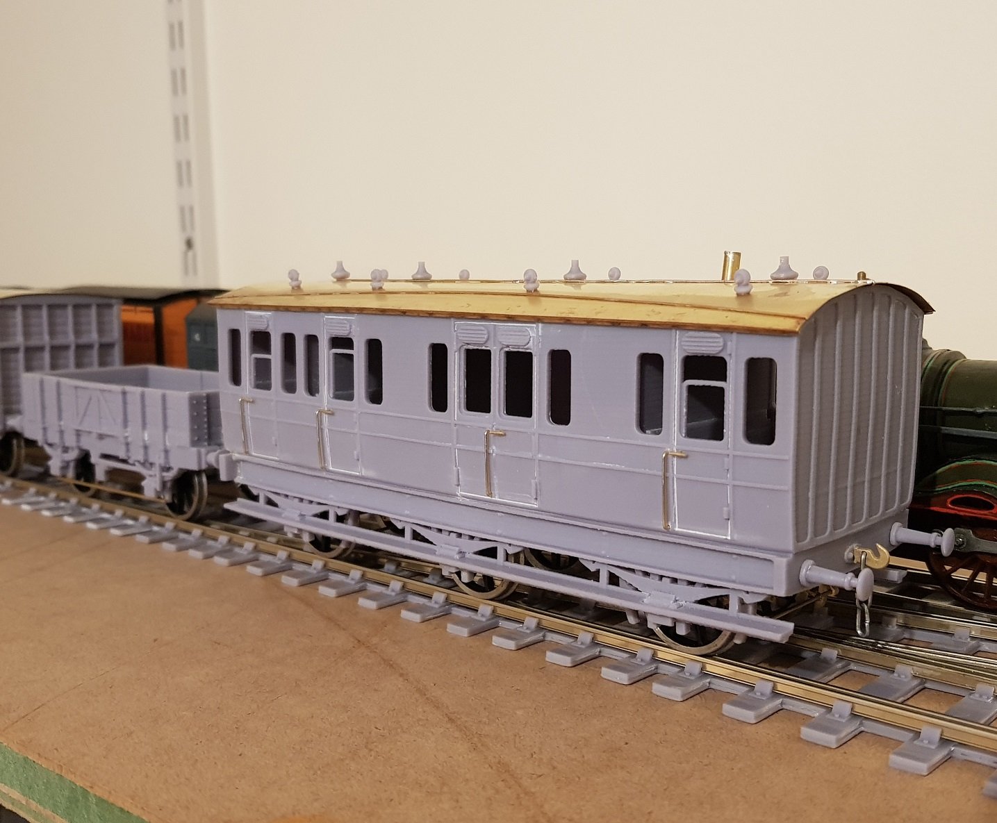
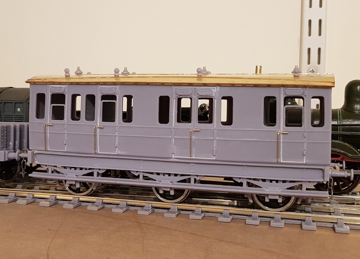
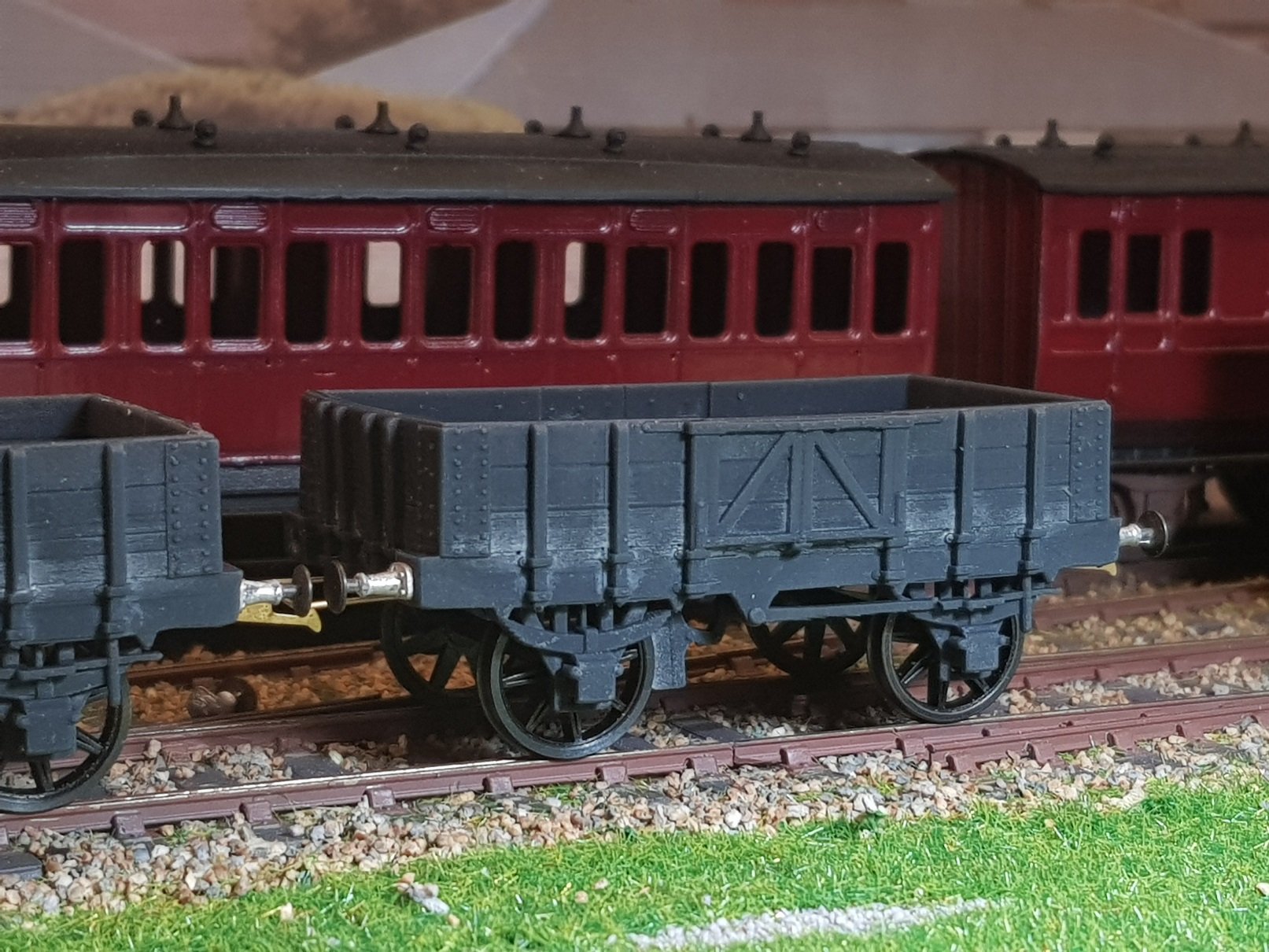
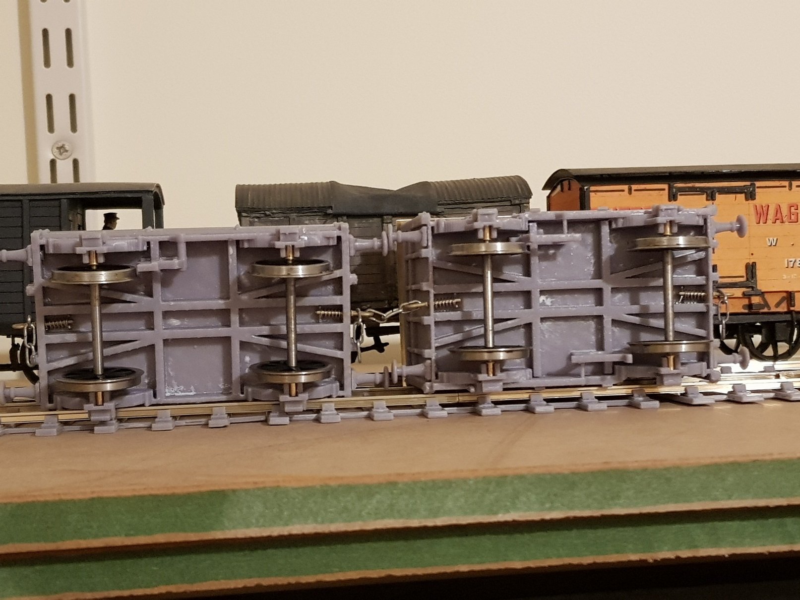
Some DSER rolling stock to go with the loco. These are a scaled up version of my 4mm models with some mods to improve the look - a basic scale up version can look a bit chunky. The 4mm models are designed for 21mm gauge, so some tweaks were required to the axle boxes to take the slaters bearings. The 3D printed roof on the cattle wagon was a bit heavy, so I went with a basic model and added a brass roof - I will probably add some fine sandpaper to represent the canvas covered roof. Slaters sprung 3 link couplings were added - I'm not going to bother with auto de-coulpling as this will be more of a display type layout than operational, so I'm happy with the "great hand in the sky". I decided to include a more prototypical under frame, albeit tweaked to allow for the 32mm gauge - this helped to reduce the floor thickness and thus printing weight. The axlebox extensions can be seen with the bearings inserted - no adhesive needed as these are a tight press fit. The underframe did make the clip on the coupling hook interesting to insert, but I got there. All in all a nice addition and will need some paint to finish them off, but they stand well with Bob's @Northroader wagons. Cheers, Ken
- 379 replies
-
- 13
-
-
-
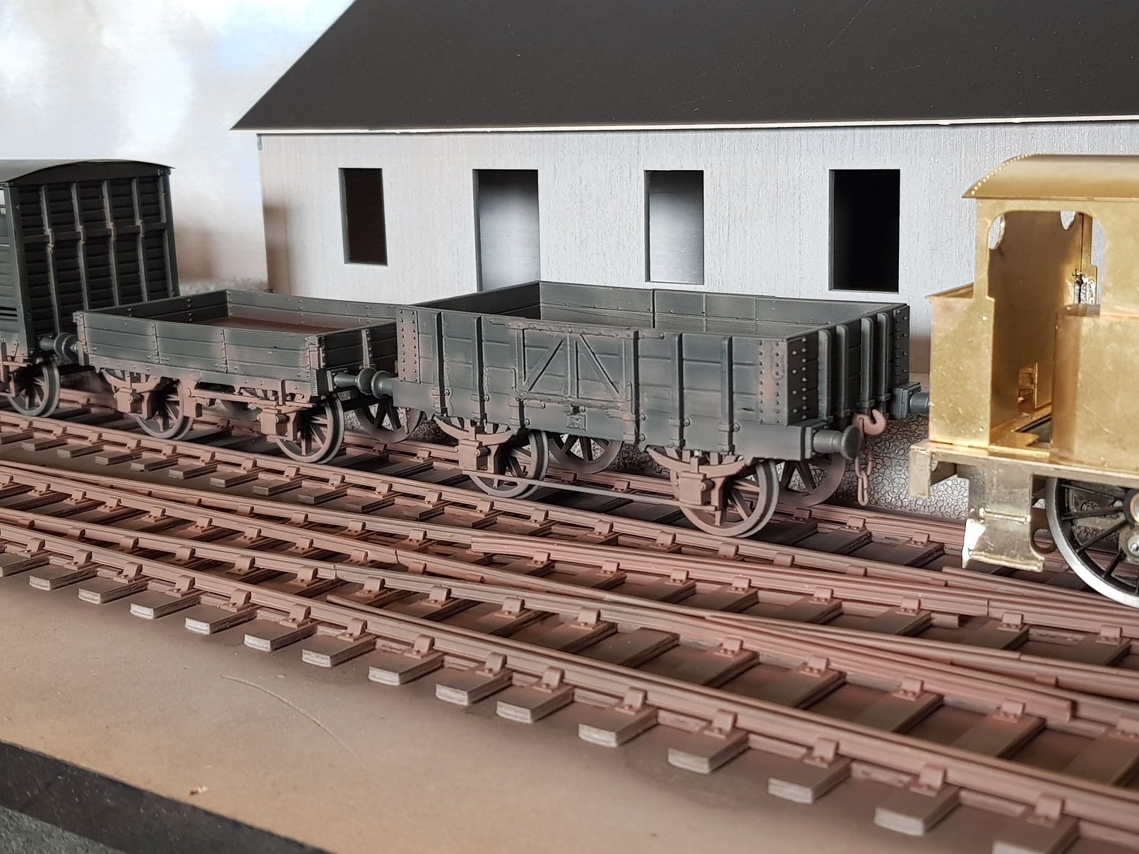
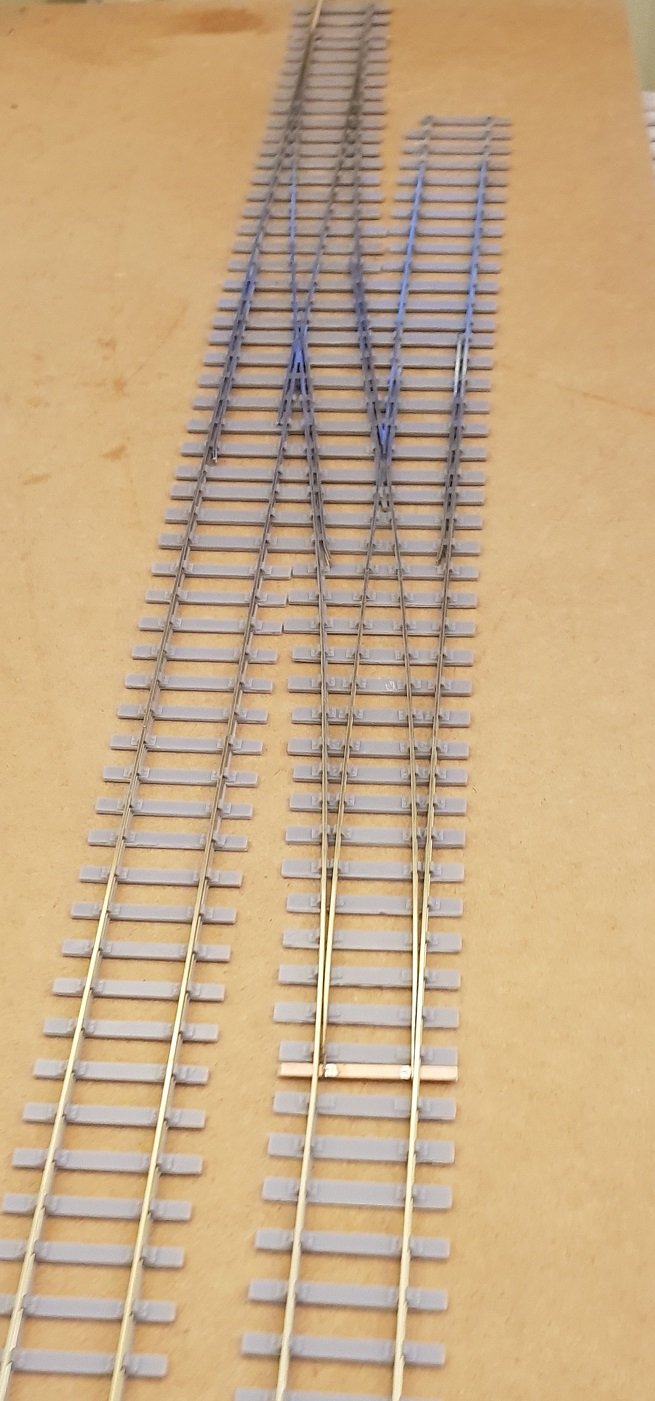
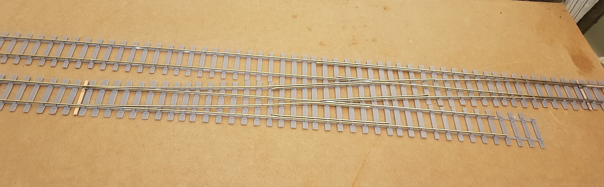
Moved slightly sidewise on the O-Gauge project. This loco, and the GSWR train already in stock, will need something to run / display on, so I decided to put some track together. A little bit of a shock when I saw the prices of points in O-Gauge, so I figured I already had some track developed for P4 which could be rescaled to O-Gauge. Simples, right? Well, it took a little more work than that but nothing excessive. So with some 3D printing and code 124 rail from Hattons it was possible to build a crossover. Experience with P4 point building helped considerably, however given the limitations of the build plate of the printer, it takes quite some to print out the parts. That said, this cost a fraction of commercial systems, so worth the effort. The thought process is to use this track in a simple layout; probably Chapel Station which was located between Macmine Junction and Palace East thus allowing for GSWR and DSER stock to appear in the same station. A very basic station with a single crossover to serve the goods shed and a headshunt to serve the cattle pens. A road bridge provides a nice scene block, and both the station and goods shed are still in existence which will help develop the model. Well, that's the plan - as things develop I will create a new thread in the layouts section. All for now.
- 379 replies
-
- 12
-
-
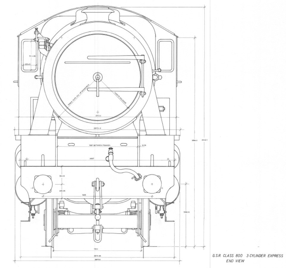
 This may help to give an idea of how the loco was constructed to maximise the loading gauge of the time. Overall dimension from railhead to top of chimney is 13' 5 1/2" or 4.1m, so this can be compared to current bridge clearance to get an idea of accessibility. Hope this helps Ken
-
I've been following this one with interest and the work you're putting in David is quite exceptional. To say the Worsley Works etches are scratch aid I think is being kind to them! After trying a few of them, I found the amount of time required to make the mods required to get to the desired end would probably equal to the time needed to scratch build the elements in the first place. Your perseverance is inspirational. More power to your elbow!!
-
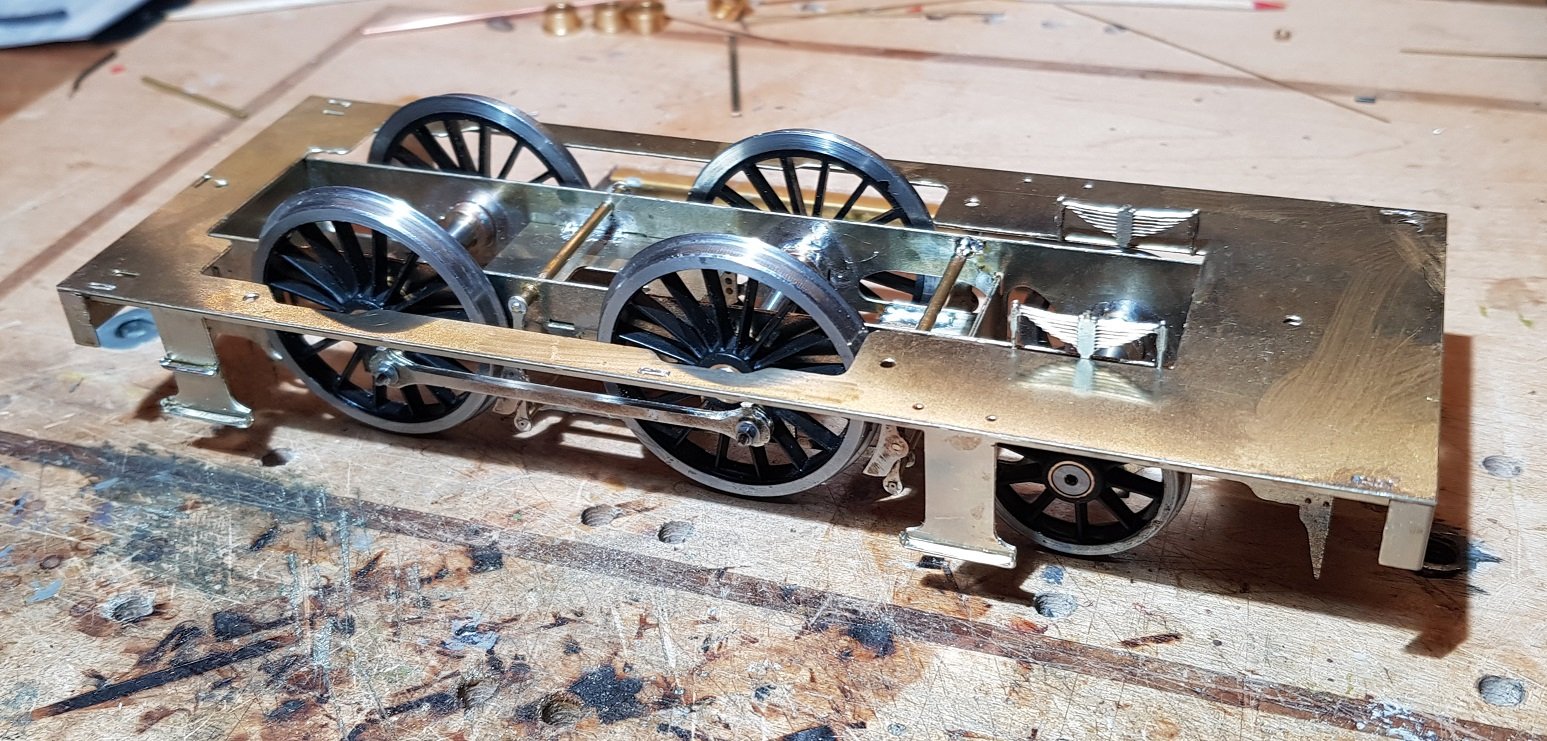
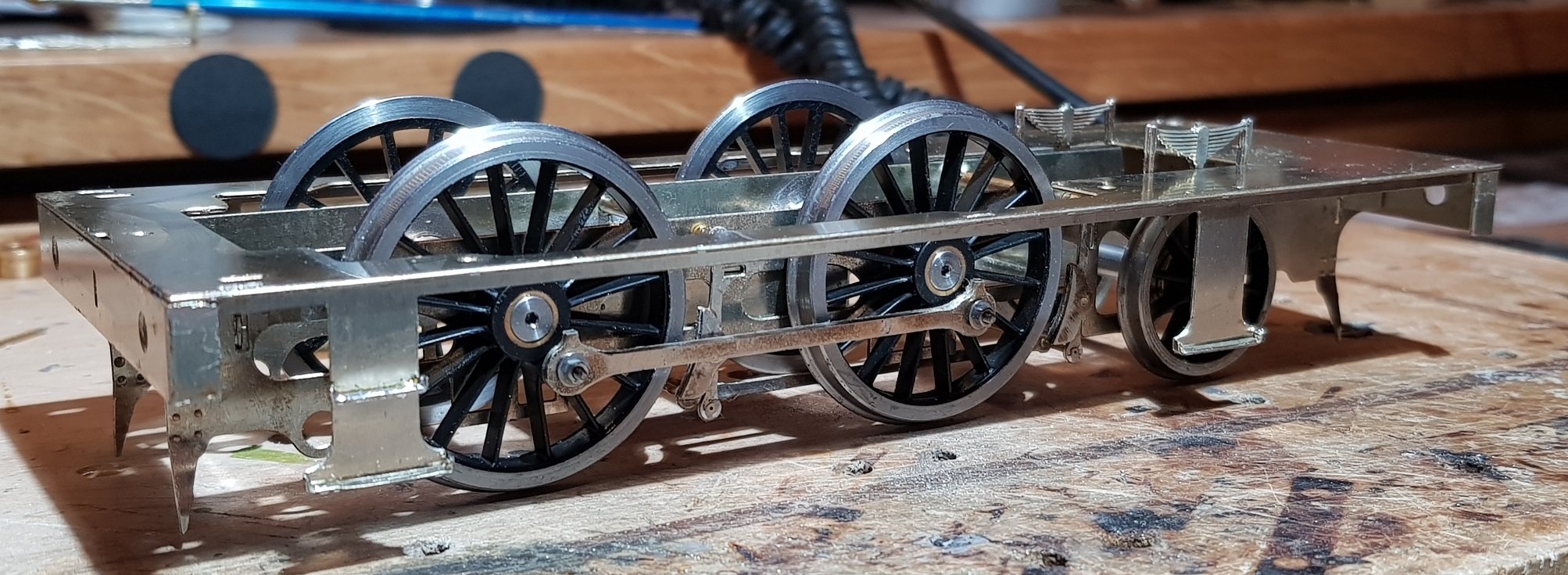
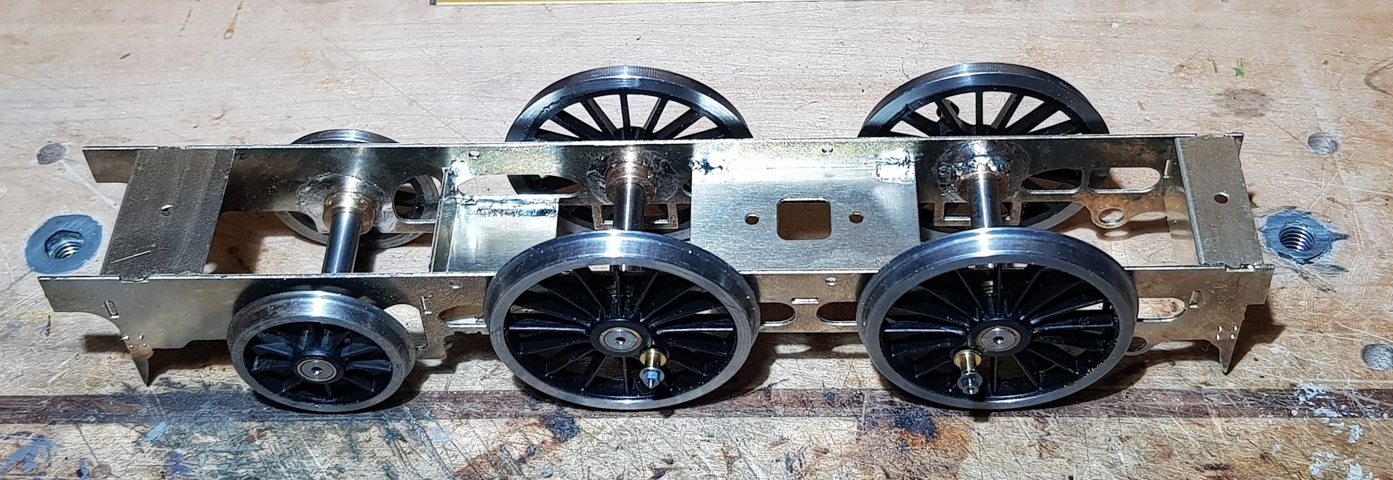
Thanks for the comments and likes guys, they are much appreciated. Agreed. Given it was the first railway and third largest railway company on the Island, it does not appear to garner much interest. Their passenger volumes were huge and freight conveyance included the usual materials, but also copper ore and cut stone materials; there is a fascinating amount of material to cover in the model world. Yes - the plan is to prepare a basic model for 32mm but provide an extra small fret with 36.75 spacers for those that would like them. Good point - the holes in the frames are designed to take the bearings accurately and I propose to allow for some movement by fettling of the leading axle bearing which would hopefully provide the necessary float. On with the build. Brakes, faux firebox sides, and con-rods were added. Con-rods were sweated together using the bushes provided with the wheels and came together rather well. Once made up and reamed slightly to ensure a free fit on the bearings they were added to the wheels. No binding and chassis rolls freely first time - first time for me also, as this work normally involves lots of tweaking to the quartering and con-rod holes to get a good fit, but this time things went well. Brake hangars and shoes were sweated together using 1mm rod to centre them. The frames were designed to take 2mm hollow tube with a 1mm inner diameter which took the 1mm rod through the brake hanger. In this way the brakes are detachable for painting and maintenance. Brake pull rods were added to set the distances between front and rear brakes and also hold the position relative to the wheels - all in all a fiddly but worthwhile exercise. Thus ends the work on the rolling chassis. On with the footplate works.... Springs were in two etches which were sweated together to provide some depth and detail on both sides. The buffer beams are designed to wrap around to provide buffer depth and soldered in under the footplate with a snug fit to the ends of the frames. The steps were half etched to allow turning up both the step and ends, and looking at them now, perhaps the step depth could be a little deeper - they look a little thin. Once steps were fixed, the valances were soldered into the slots in the footplate with the front slots needing some solder to fill the hole - the rear slots will be hidden by the tanks. So completes the Nickel Silver work and we are up to footplate level - onwards with the brass work to provide a body. All for now. Ken
- 379 replies
-
- 10
-
-
-
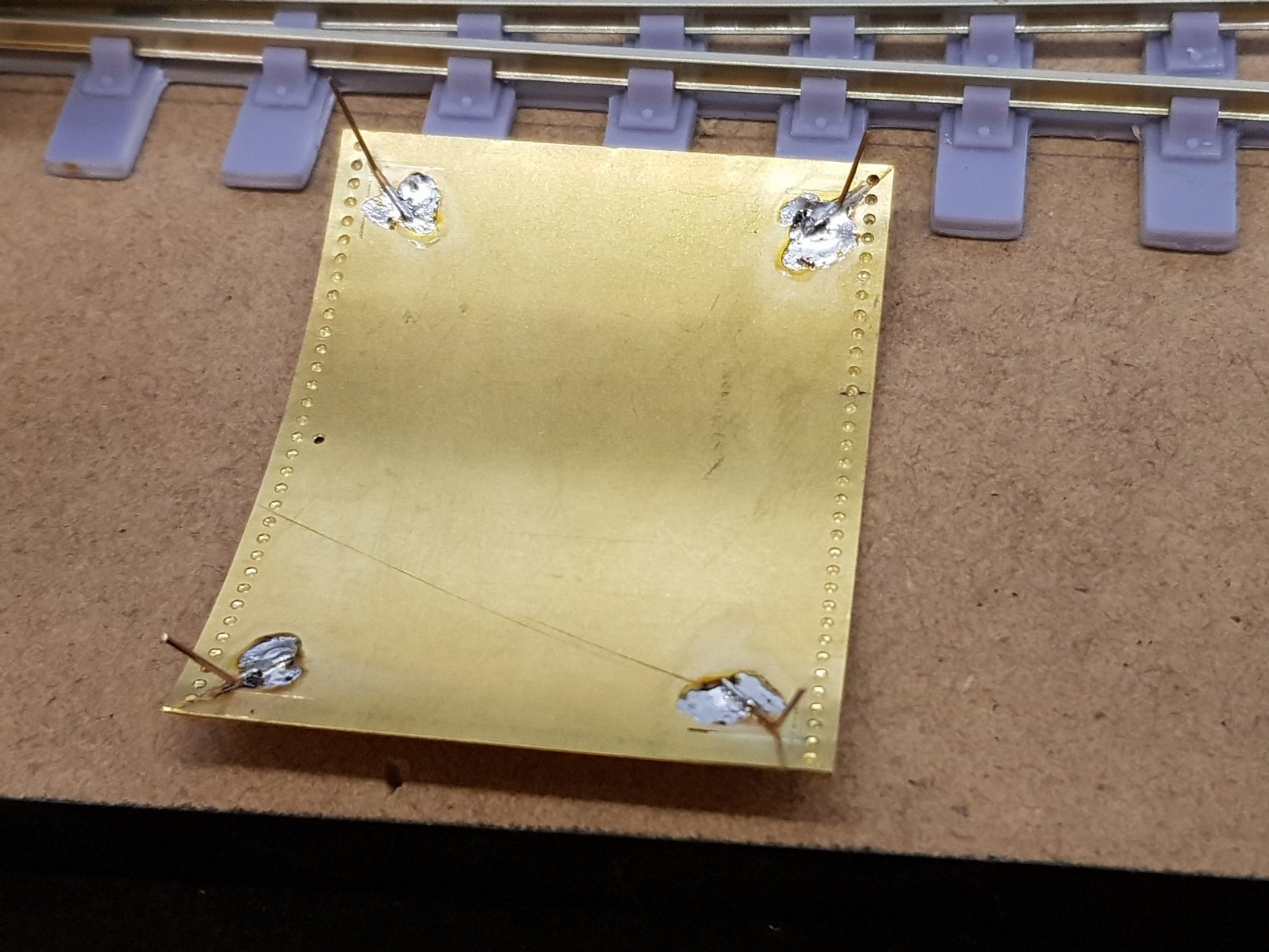
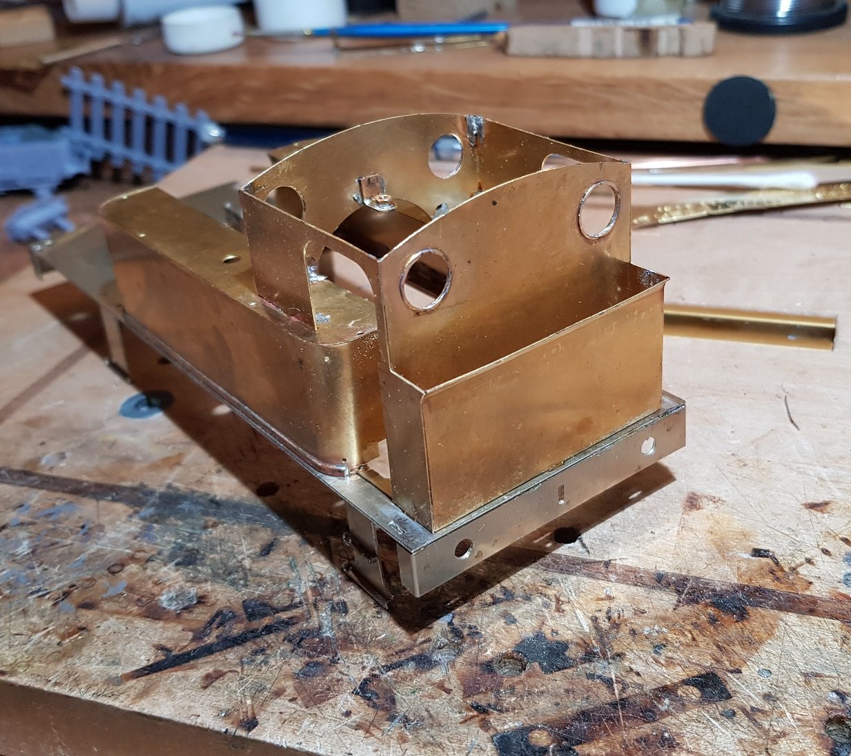
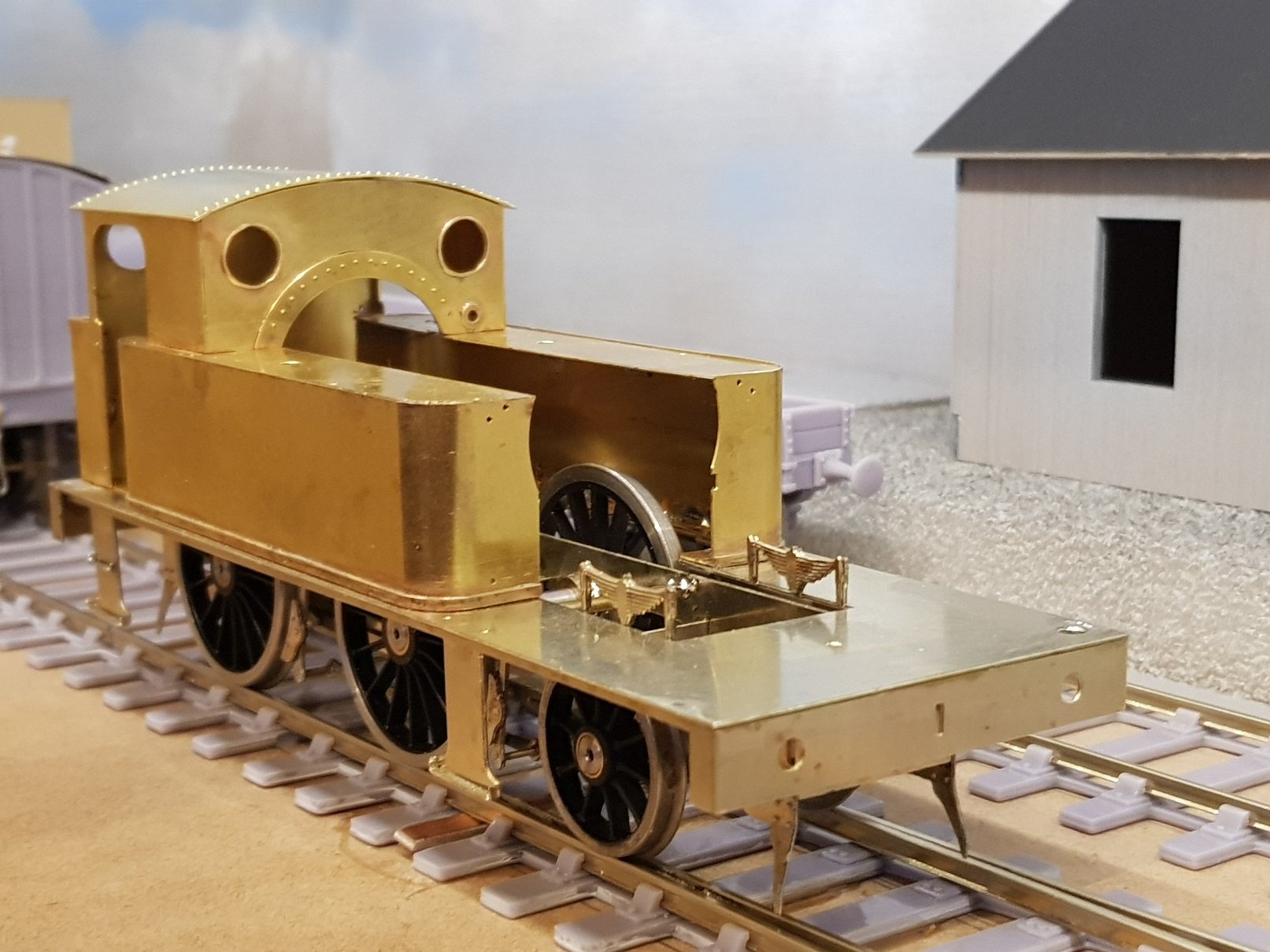
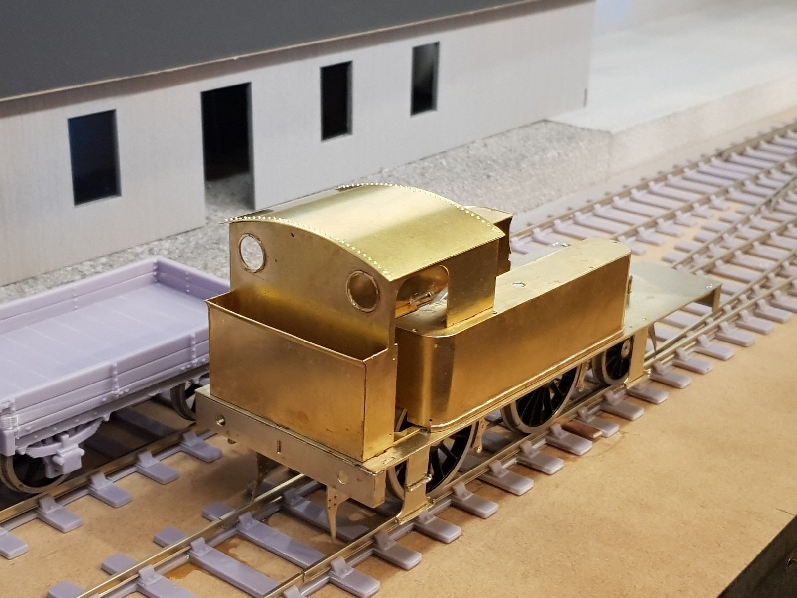
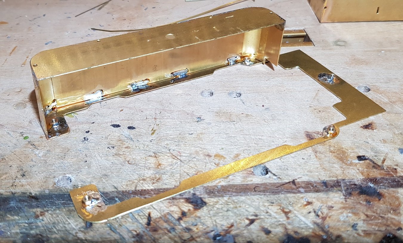
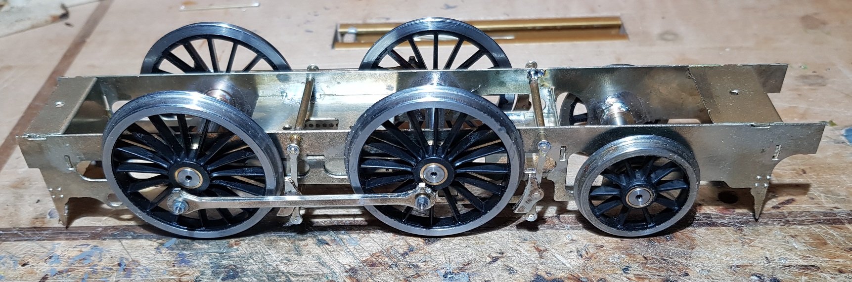
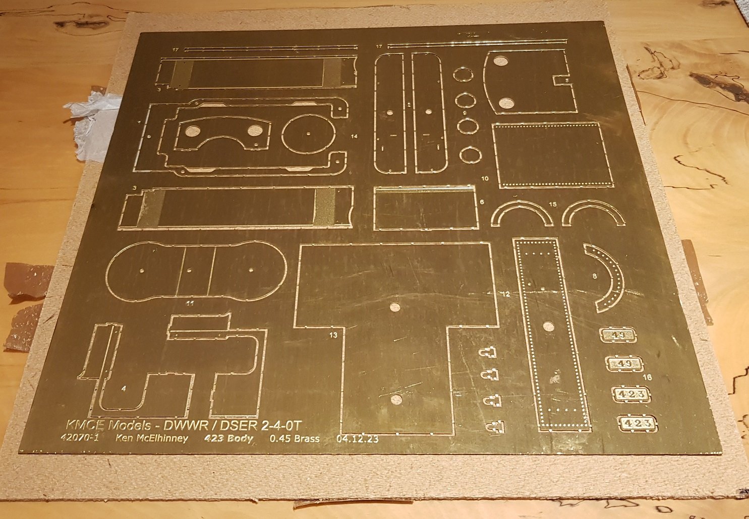
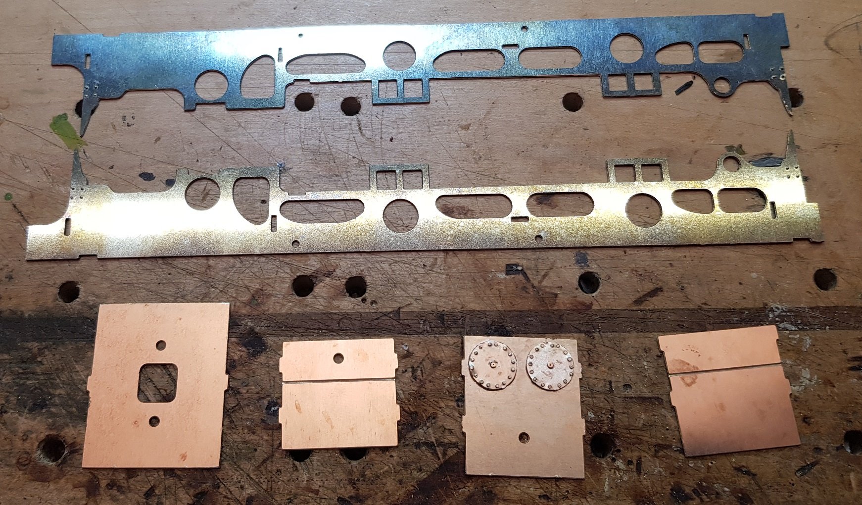
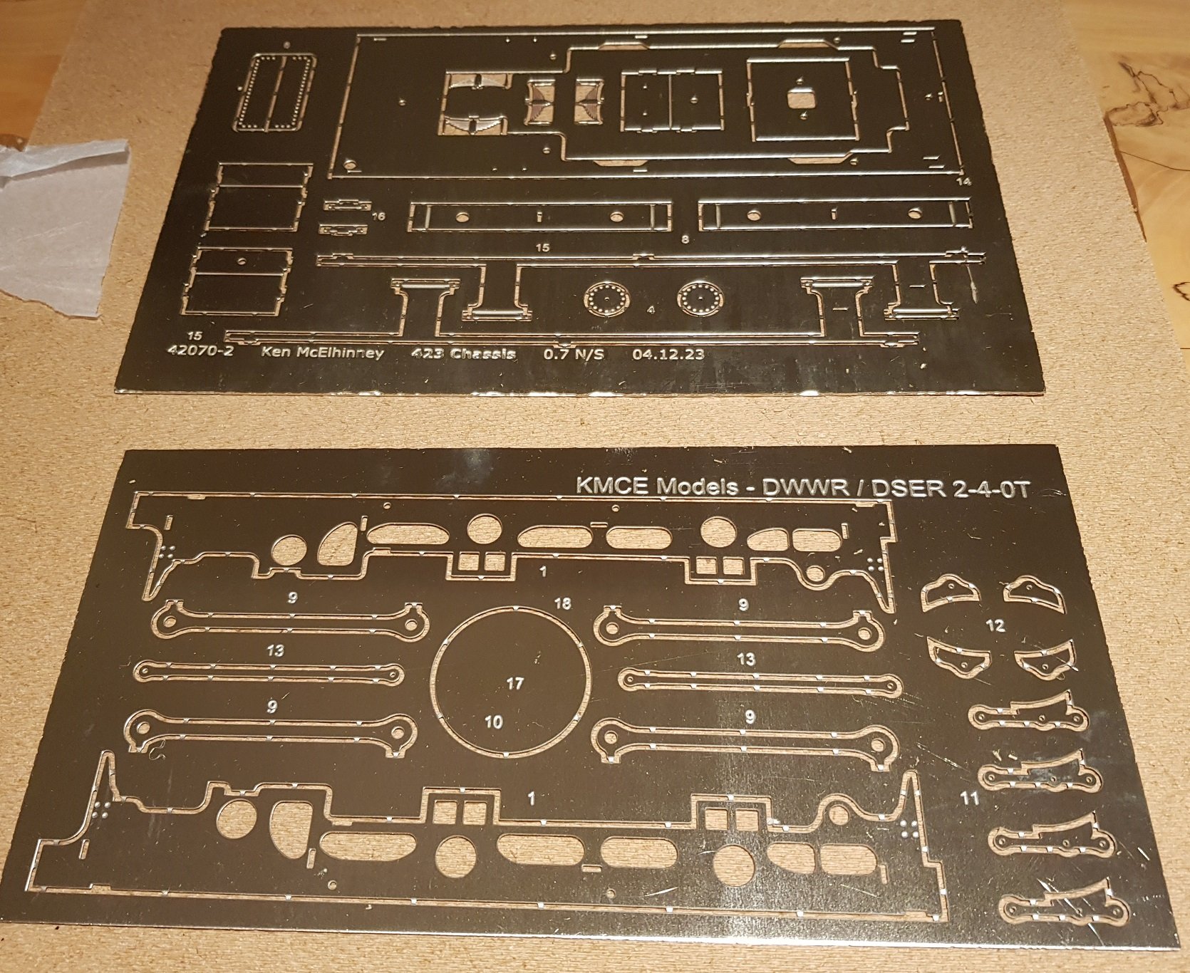
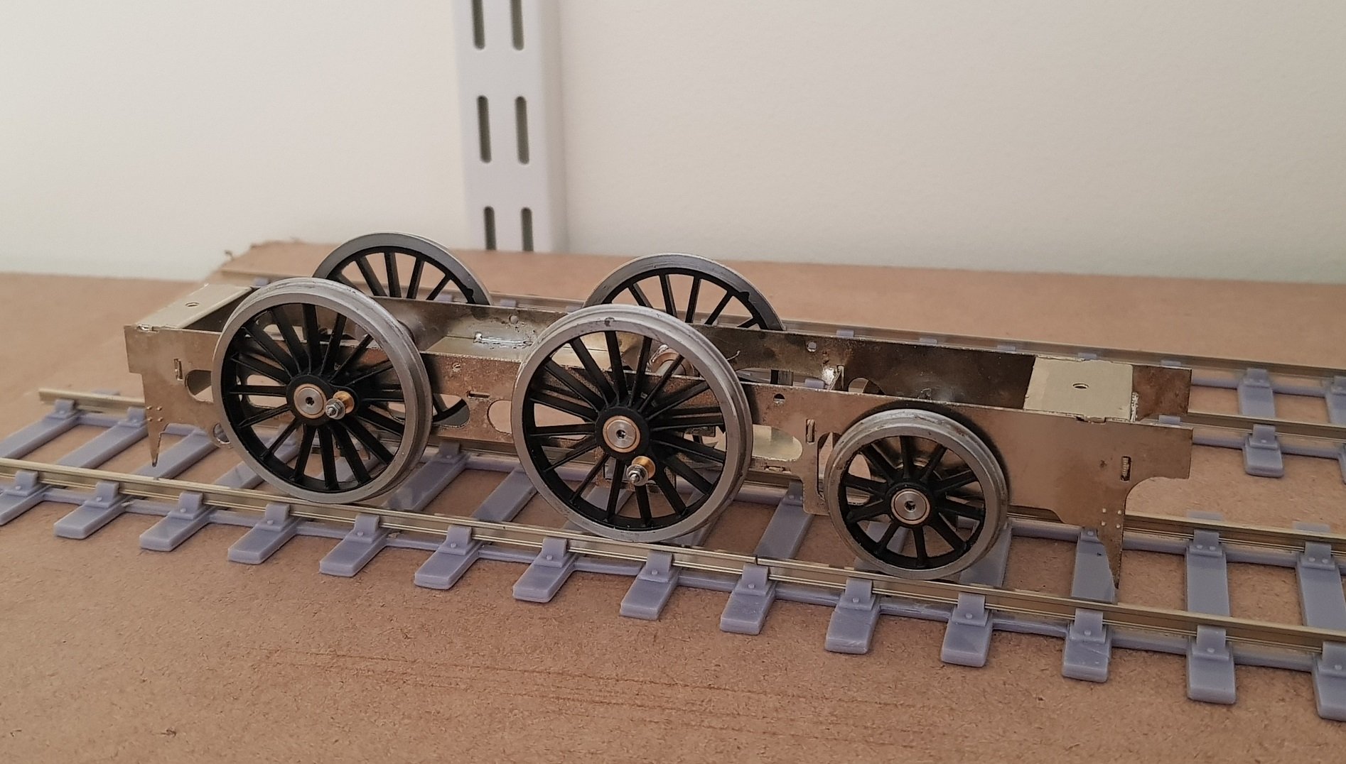
And now for something completely different! I have been asked by quite a few people if I could develop the 423 Class locomotive for 7mm O-Gauge, and naively said "sure - no problem". Well it wasn't quite as easy as just scaling the 4mm kit to 7mm and sending off to the etchers. Metal thickness changes needed some tweaks to dimensions, and even at that some tabs are not lining up - but that's getting ahead of myself. It took some time to develop the etches as I had no bearings, couplings, etc to properly dimension the chassis etc, and a spat between An Post and Royal Mail meant an order with all those parts got stuck in Dublin for c. 10 Weeks - luckily Slaters sent it by courier the second time and it arrived. Some frantic work and a push with the etching company (PPD) meant I got the etches before Christmas. Great - a nice pressie for me!! Brass fret in one piece - lesson No. 1: Need to break this down into two. It measures nearly 300 x 300mm so probably would be better as two frets. Not the only problem - the etching didn't quite go to plan - the 4 disks to the top RHS should be spectacle rings for the openings in the cab. Guess I'll just have to use soft brass wire to make them on the prototype. I will be in touch with PPD regarding this and other errors, as they appear to be issues on their side - when I checked the artwork, it should have etched properly. Then Nickel Silver fret for the chassis (0.7mm) was in one piece, again a little large at c. 250 x 250mm, however PPD split this over two frets which makes more sense. Another error is the parts labelled 10, 17 & 18. 10 & 17 make up the reversing lever detail, while 18 should be a ring which helps keep the boiler at the correct external dimensions whilst soldering the seam. It's the best way I have found to solder a boiler without resorting to wire & clips etc. Again all good on the artwork, so I'll get in touch with PPD to discuss. In fairness to them, they have responded very well to issues in the past with other kits, so I don't expect a major fuss. Anyway the purpose of all this is to make a 7mm O-Gauge prototype of the DSER 423 Class loco. First up, chassis parts and spacers. Faux cylinder heads were etched and the rivets popped out (with a rivet press due to metal thickness) and fixed to the front spacer. Spacers were folded as necessary, however the spacer on the very left was too wide. Essentially the kit was scaled up from 4mm (21mm Gauge) and spacers adjusted accordingly, however this one appeared to slip through the process - a quick snip with the shears got it down to size. The chassis has been developed to take fixed bearings and has no compensation allowed for - I have noted (perhaps incorrectly) that most 7mm modellers prefer to use fixed bearings, so this is the route I have taken. Some standard brass bearings were fitted to the frames and frame spacers fixed to one side. Again, another gotcha - due to the metal thickness and the bend, some of the tabs did not line up properly which needed an element of filing to get them right. This can be amended for the Mk 2 version along with other minor errors. Using the axles it was possible to solder up the second frame to the spacers and all checked for squareness and flatness - thankfully this came together quite well and didn't require much work. A small amount of fettling was needed to ensure the axles ran free, but once wheels were on, everything lined up perfectly and all wheels are even on the rails - no rocking! One thing I am finding is that this is big! As I was building it, I was convinced (more than once) that I had got the dimensions wrong and oversized everything. Putting it on the track and comparing to the loco and wagons I have shows it is correct - guess I am tuned to 4mm? Anyway, all for now. Next up, faux firebox sides, connecting rods, and brakes to get a finished chassis, but so far, so good. Ken
- 379 replies
-
- 13
-
-
-
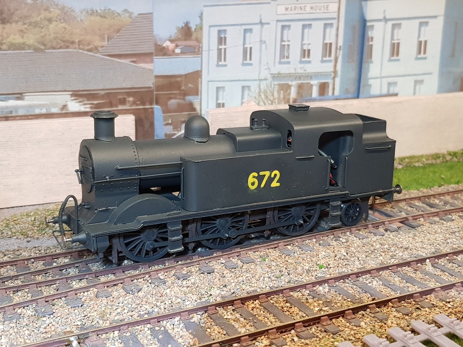
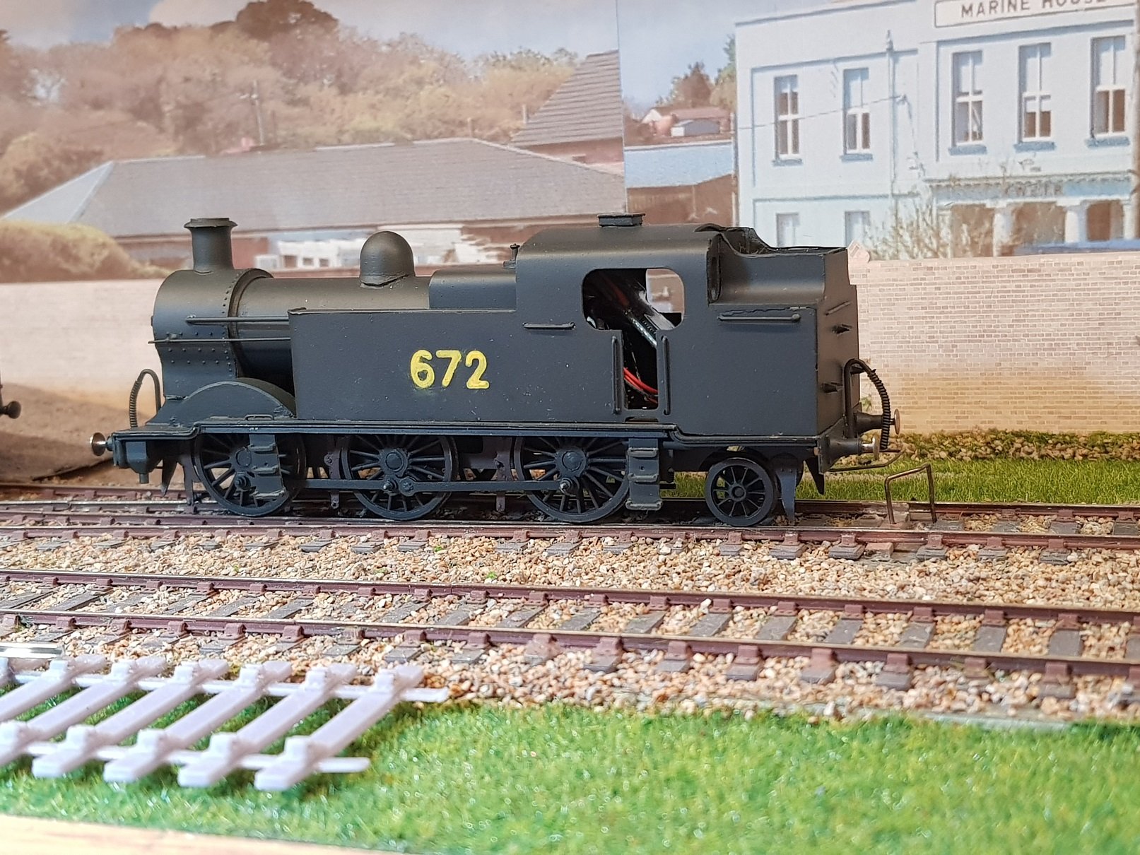
So, a quick update on the 670 class. The problem child has finally grown up and but for a few snags is ready to join the fleet. The coat of paint helped to blend in the harsh elements and bring things together. Still a few elements to tidy up - a bit of filler needed on the steam dome and the numbering needs tidying up. A touch of paint on the buffer beams would help too. Not withstanding those bits, it has come together rather well given the problems. Electrical elements need to be tidied up as well - I had the chips taped to the underside of the roof which worked before, so will probably do that again. Quite a lump of a locomotive and considerably bigger that the earlier 423 and 428 classes, so easy to see why they ended up with a train of bogey coaches running on the Bray line. Anyway, enough of that for the moment - I'll get back to it at some point to do the snagging. Ken
- 379 replies
-
- 17
-
-
-
I feel your pain David. Having built quite a few of those High Level gearboxes, they are both fiddly and exceptionally well designed. Once put together successfully they are bulletproof - key is getting them together properly. If found that the gearbox sides must be absolutely square - I know it sounds simple and straightforward, but even a small amount out of square can cause running problems. The additional small strap in the fret fits across the back of the gearbox opposite the motor side; those tiny pips on the fret are not etching issues, they help locate the small strap. The strap helps to stabilise the sides of the gearbox but also provides space for an additional bearing to support the motor shaft which helps hold the worm gear firmly in place. I would hazard a guess that the reason your first gear was stripped was due to the motor not fixing tightly to the gearbox and/or lack of bearing supporting the end of the motor shaft after the worm gear. I have had problems in the past with this, but I'm only trying to move 4mm chassis - moving a 7mm chassis & later body will probably need the motor shaft bearing. The hole in the small strap is quite big, so if the motor shaft is not long enough, it may be possible to extend it with brass tube through the strap, thus securing the worm gear firmly to the first gear? Hope this is of help. Ken
-
Some very tasty work, Sir. Nicely done!
-
Now, they look well. Nicely done Sir.
-
Frustrating when it turns out to be something "relatively" simple. You then think of all the work you did and quietly reach for your handy book of expletives.......