KMCE
-
Posts
540 -
Joined
-
Last visited
-
Days Won
29
Content Type
Profiles
Forums
Events
Gallery
Blogs
Everything posted by KMCE
-
Nice work on the carriage - it has that aged, lived in look. Excellent weathering! Agree with the comments on the etches - been there and still have the tee shirts....
-
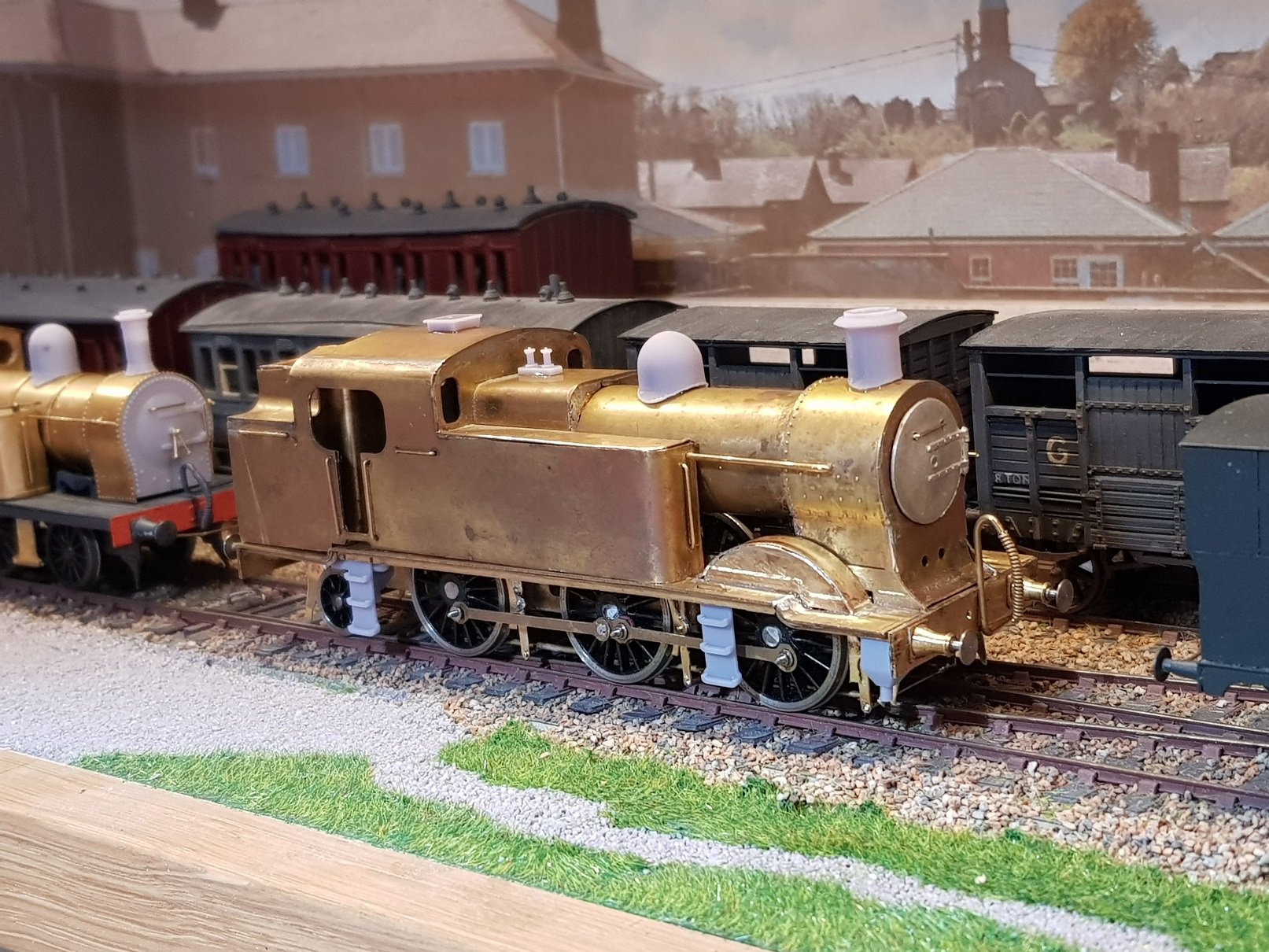
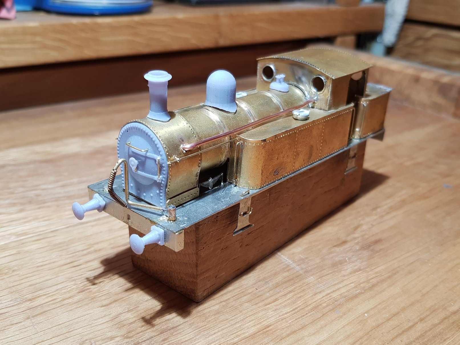
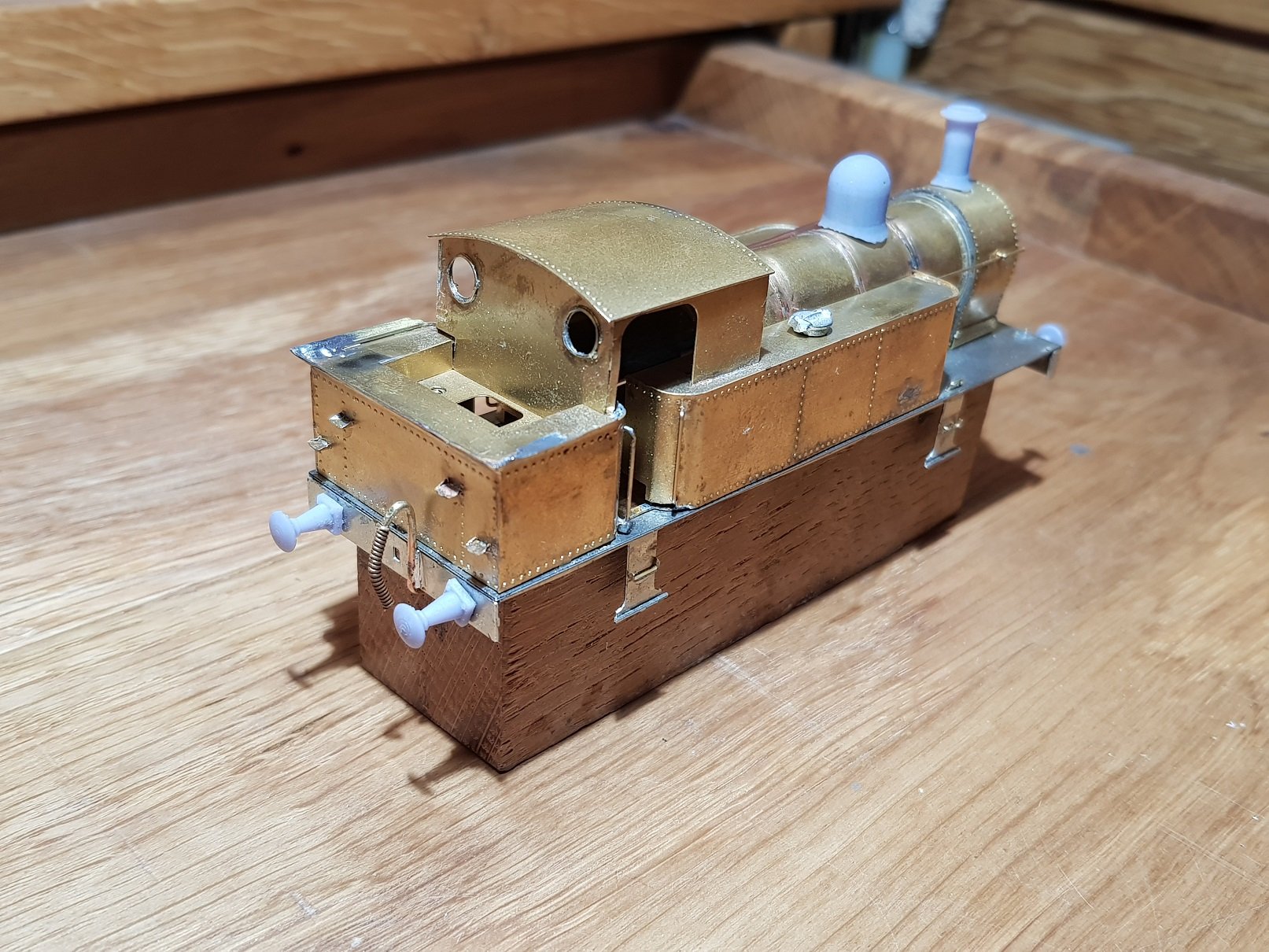
So, I started this 670 Class loco in Nov 2018 (yes 5 years ago!!) - this one being a real problem child, in every sense; on and off the workbench many times. Chassis was built twice, brakes probably 3 times, and front splashers, I've lost track. However in a concerted effort to get it finished, I spent some time recently to try and get it completed. There are still some issues to be worked on, well quite a few issues, but I'm getting closer. The 3D printed parts help reduce the workload as those steps proved almost impossible in brass. Front steps will need some brass reinforcement as they are wandering a little too much, and I think I will need some additional fixings to hold the body down to the footplate at the rear, etc, etc. Getting closer & I'll post more as progress permits

- 379 replies
-
- 13
-

-
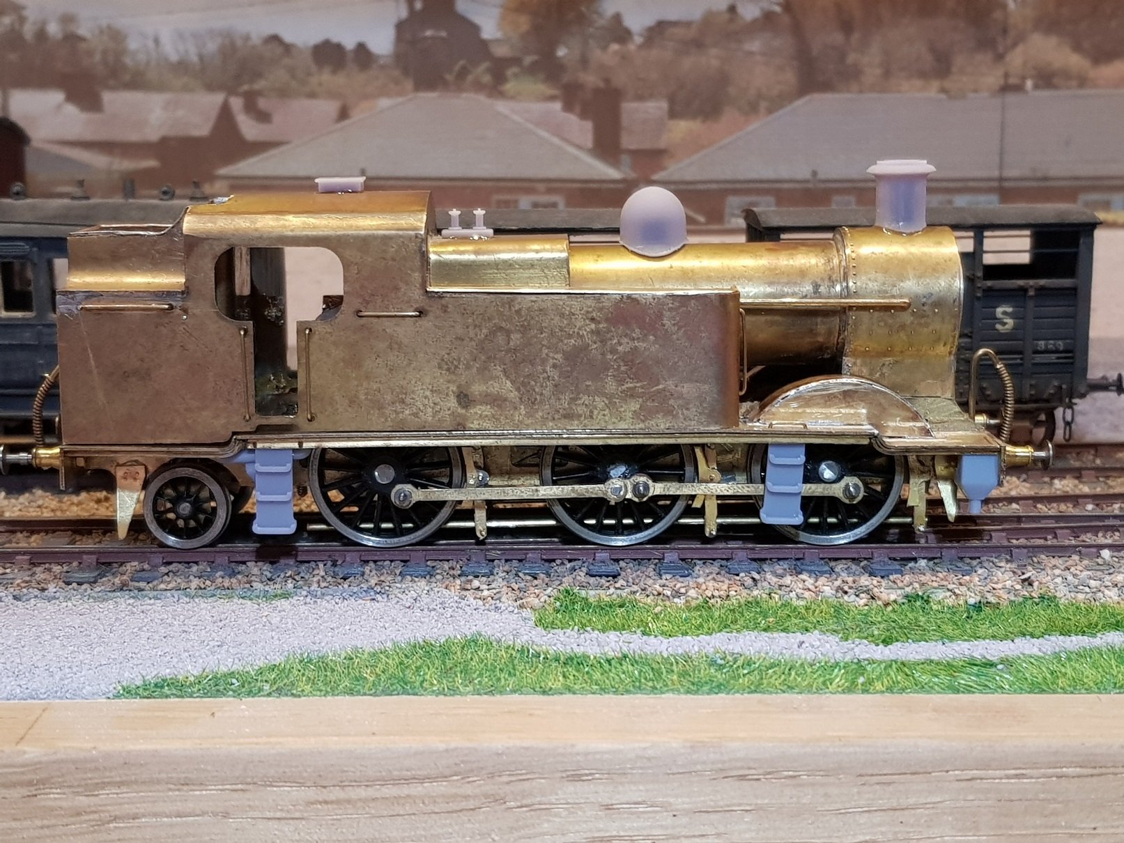
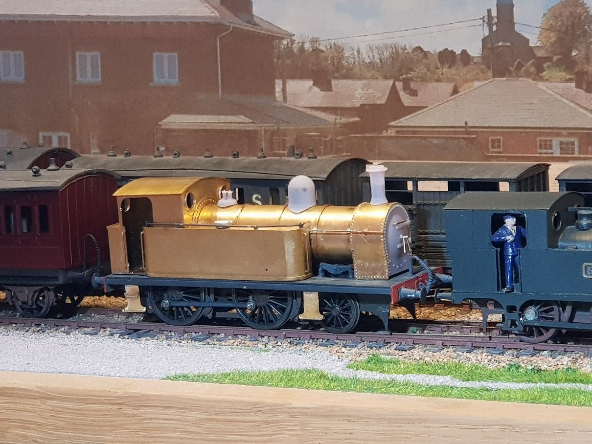
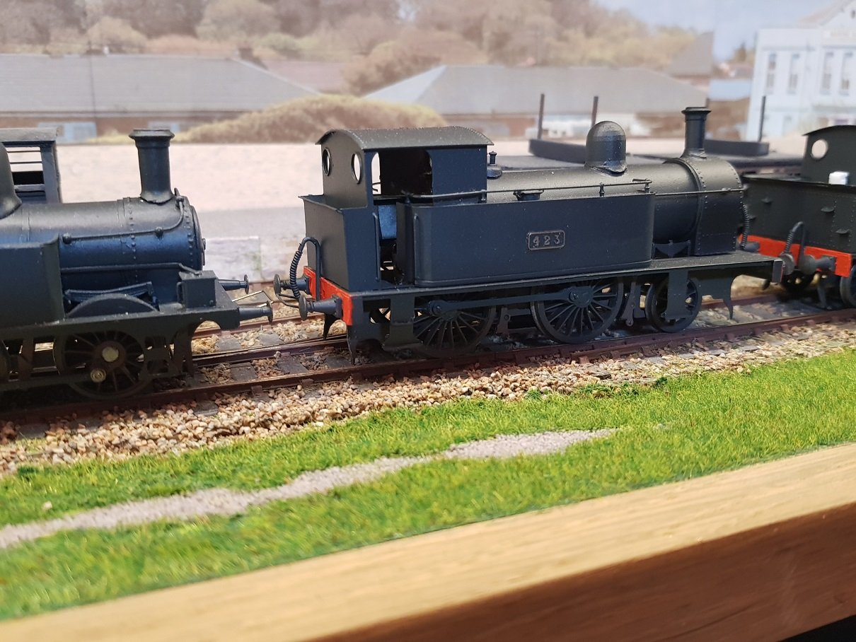
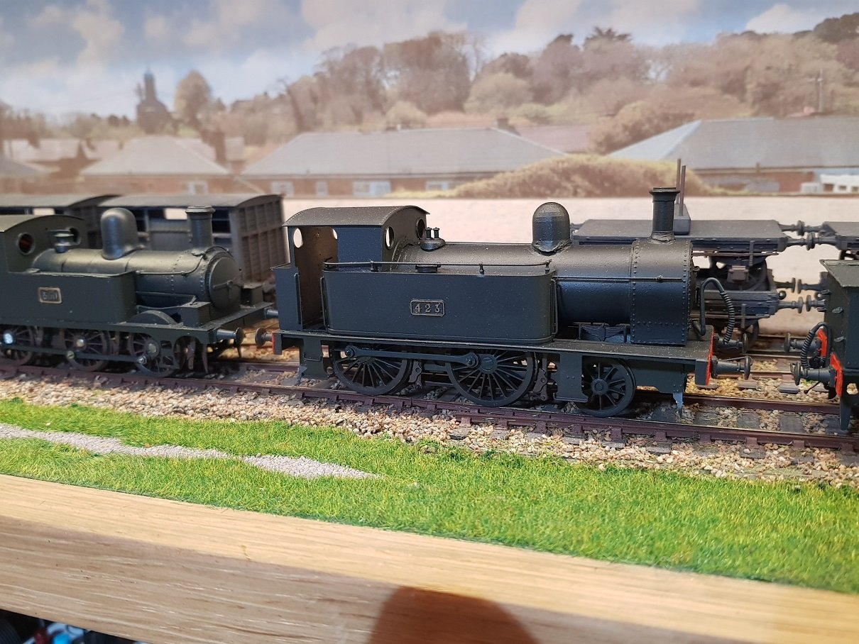
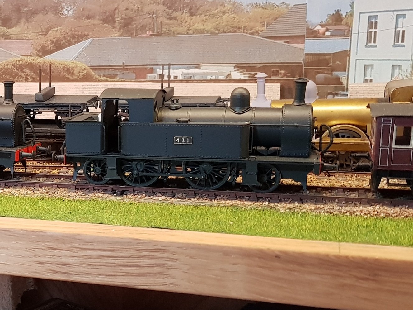
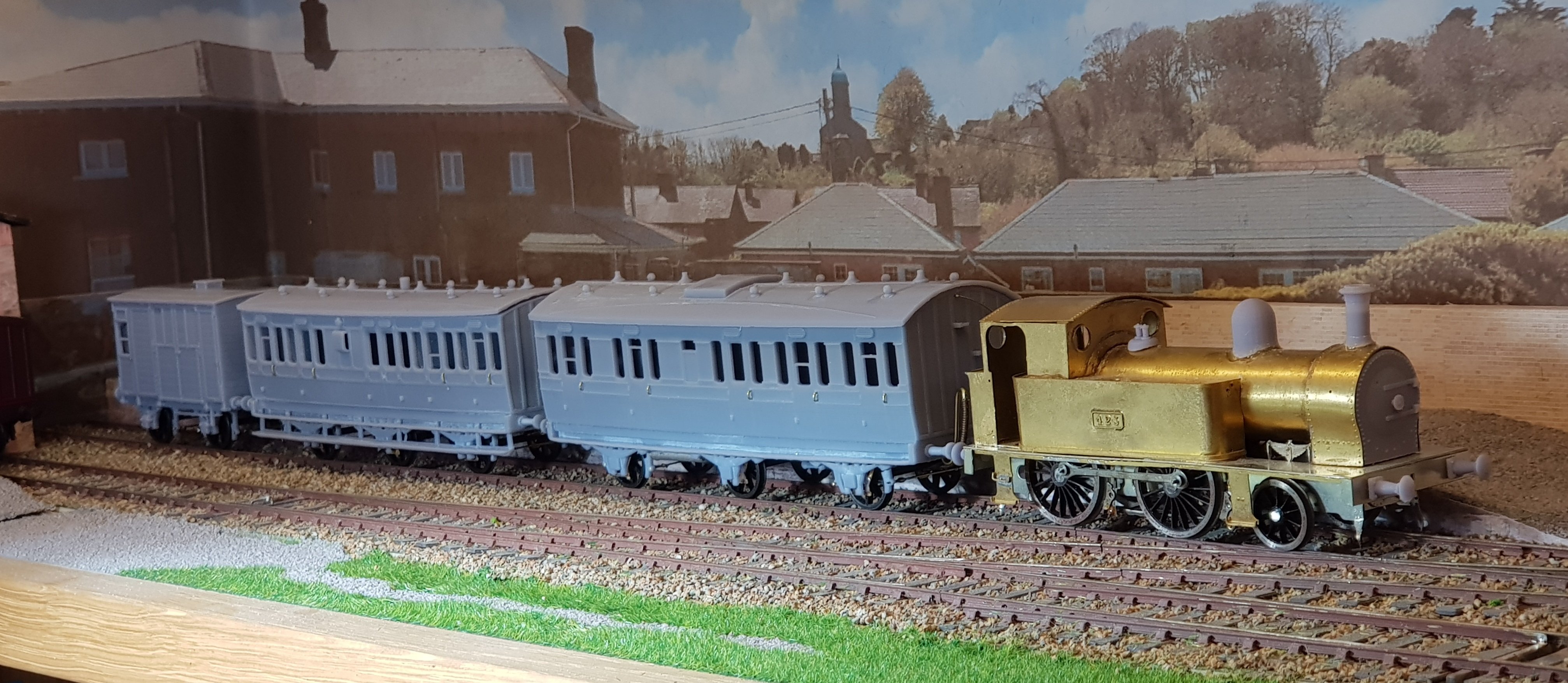
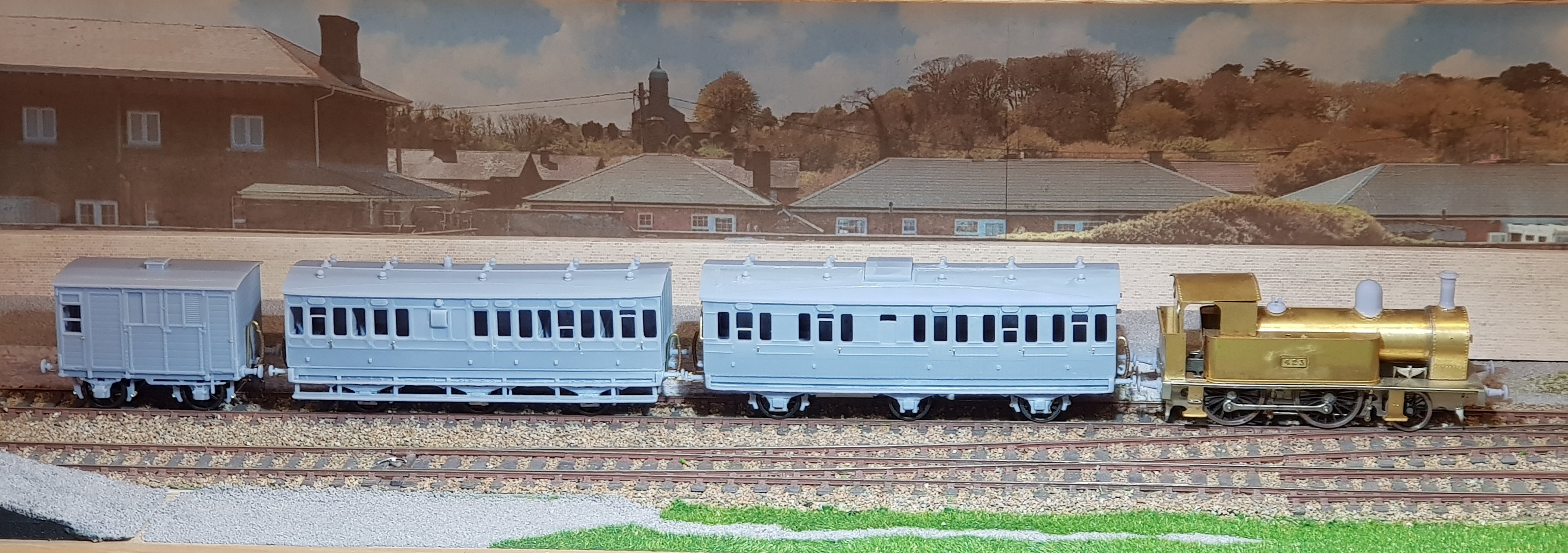
Some additional loco work has been underway recently. The 428 class loco got a number plate - 431 in this case as it works with designations on my RC controller. The 423 class kit was finally completed and painted - some tidying up needed, but it has turned out rather well. This was the MK1 kit which required some mods to fix minor errors. The original scratchbuilt 423 got a new superstructure courtesy of a MK2 kit spare etch - this corrected some errors from the Mk1 but has been further refined for the Mk3 kit, again minor tweaks, but I prefer to fix the errors as I find it quite annoying when assembling a kit to discover errors that need fixing. 428 Class with number plate added, but some weathering needed to finish. The new 423 with light weathering - I think a heavier belt with the weathering brush will be needed. Old 423 with new superstructure with the old chassis. The plan is to paint this in DSER black with lining to go with some DSER stock (about time I hear you cry)!! Finally a quick line up outside the work: All for now... Ken
- 379 replies
-
- 17
-
-

-
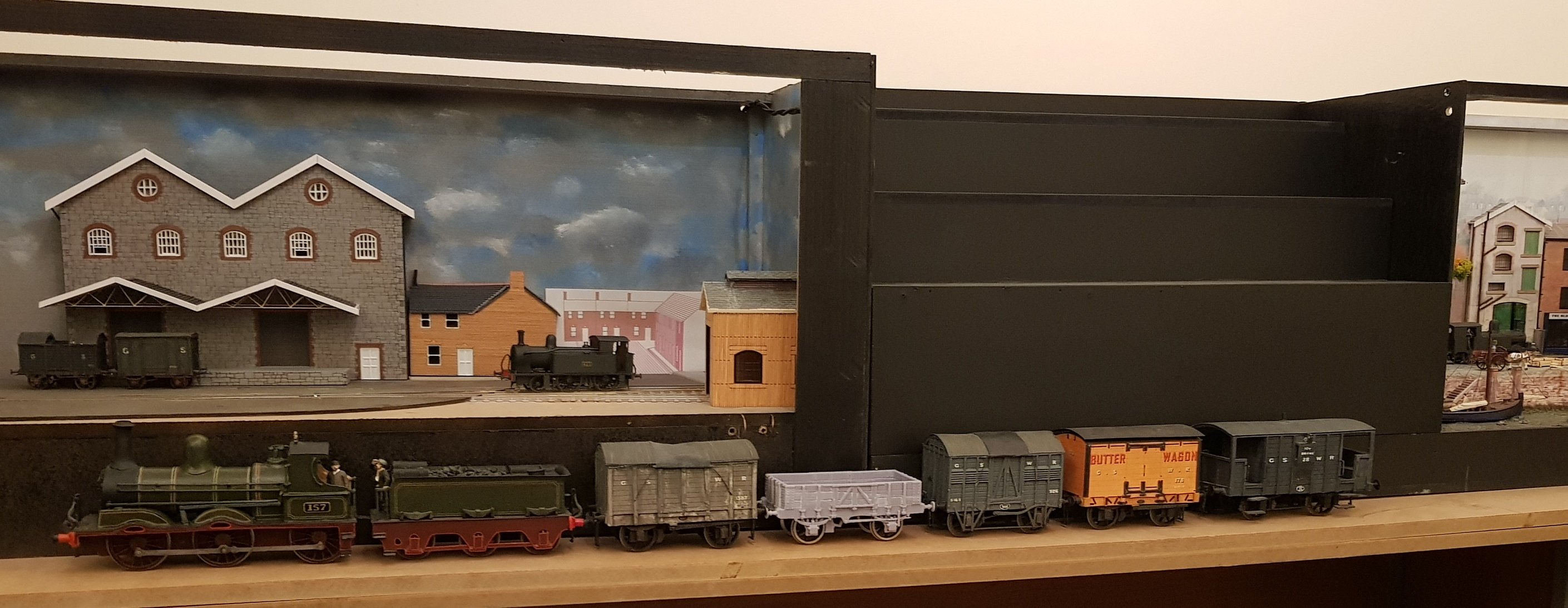
Thanks Leslie for "transacting the deed" and once again, many thanks Bob for the opportunity to bring the train to its new home where it will be treasured. A quick photo in front of the current P4 Layouts: It may have some stable-mates soon......... Watch this space! Ken
-
That is looking excellent. It clearly takes a level of patience that I would not be able to demonstrate - give me CAD any day!! Ken
-
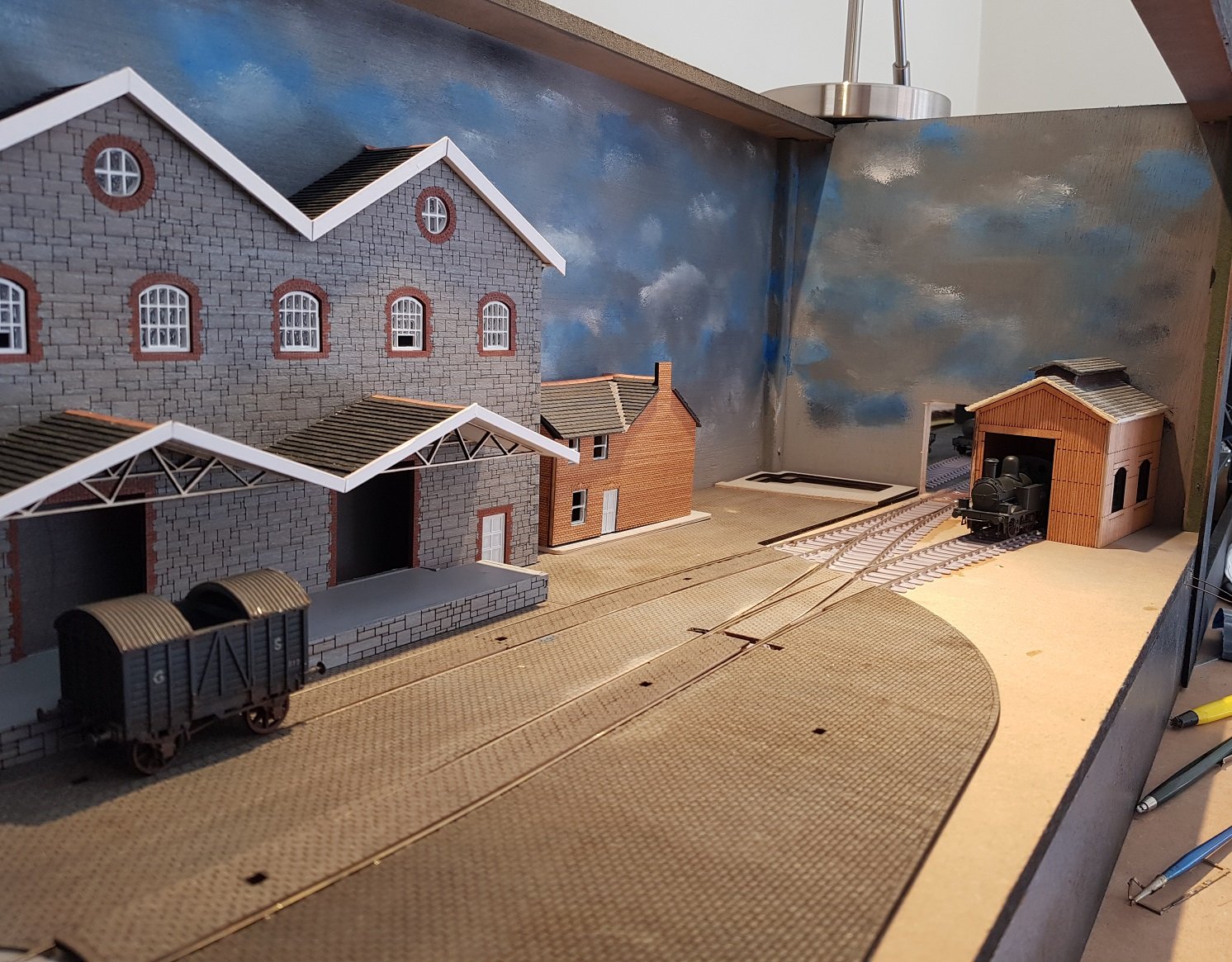
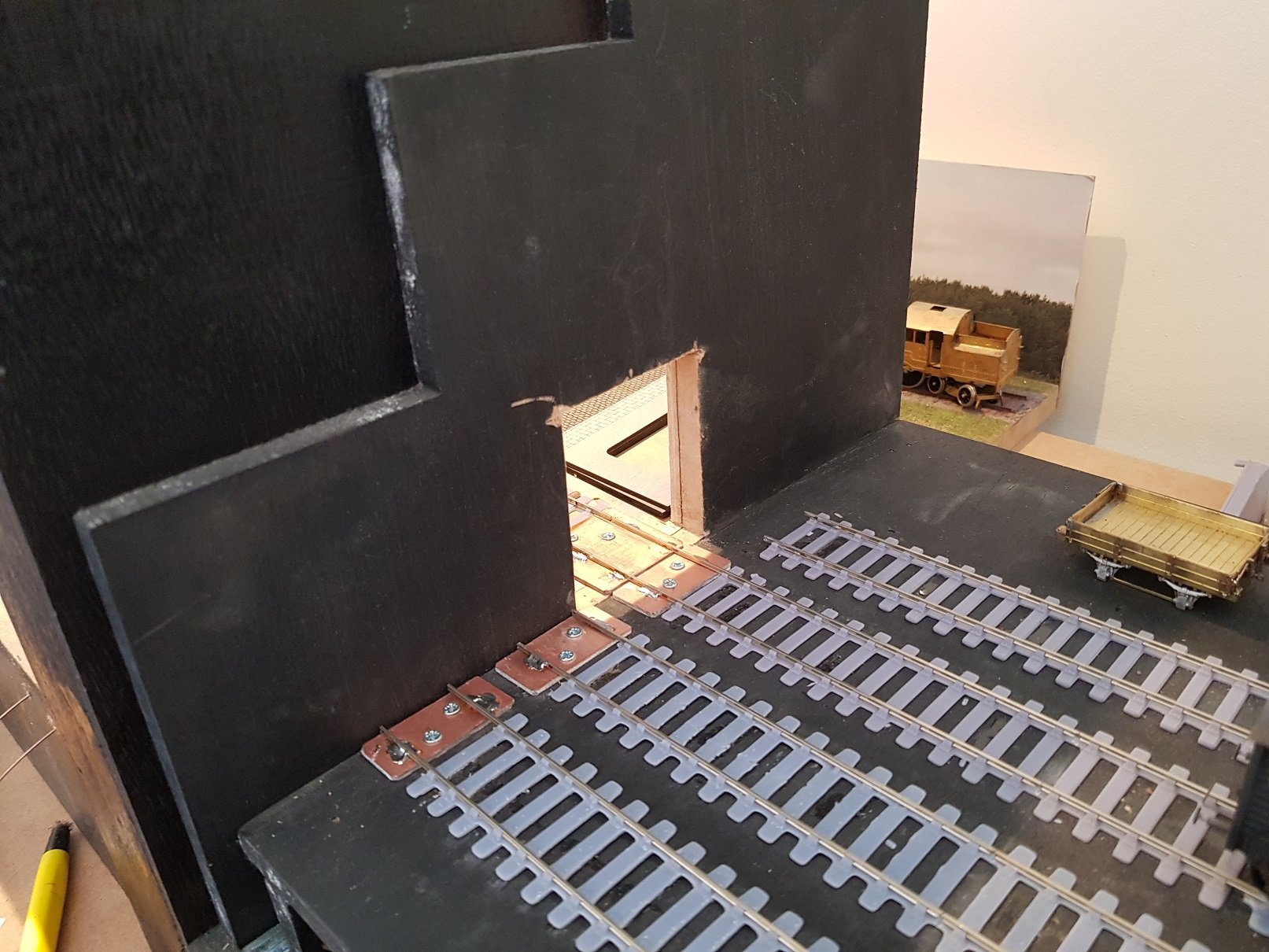
So, lots of work done on the layout. The laser cut cobblestones turned out quite well - this also helped to set the track into position. Cobbles outside the tracks has be glued into position whilst infill sections are just loose for the moment. Turntables are fixed down with some work to be done to settle the tops into place - the 3D printing has left the underside of the tops quite rough which will need some tidying up to get them to set down properly. Keg fab building has a corrugated roof which will be painted down to represent asbestos. Keg building has the roof added, platform and canopies located, however steel uprights need to be added. A view looking back towards the loco shed and scene entry - space in the corner will be filled by housing and a wall to separate the track from the street. The space outside the cobbles will be dressed as waste / unused ground which will help bring some greenery to the scene. Incoming track will be ballasted, whilst the track to the loco shed will be mainly ash. Some other work includes connection of point operating levers and copperclad connections between traverser and incoming track. Some sky painting done, but it looks a bit dark in these photos - I may lighten it up... The traverser will only provide three line connections whilst the port has access to all four - it will not be possible to run directly from one scene to another; the traverser will need to move by one line to allow a train move from one scene to another. Lighting has been added in the form of strip LED under the front valance, but was not installed for these photos. For those going, the layout will be in Bray tomorrow, so hope to see you there. All for now, Ken
- 16 replies
-
- 21
-
-
-
Very nice indeed - level of detail, paint and weathering is excellent. I trust your client is happy!
-
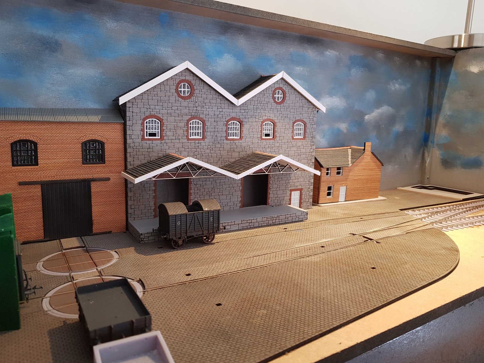
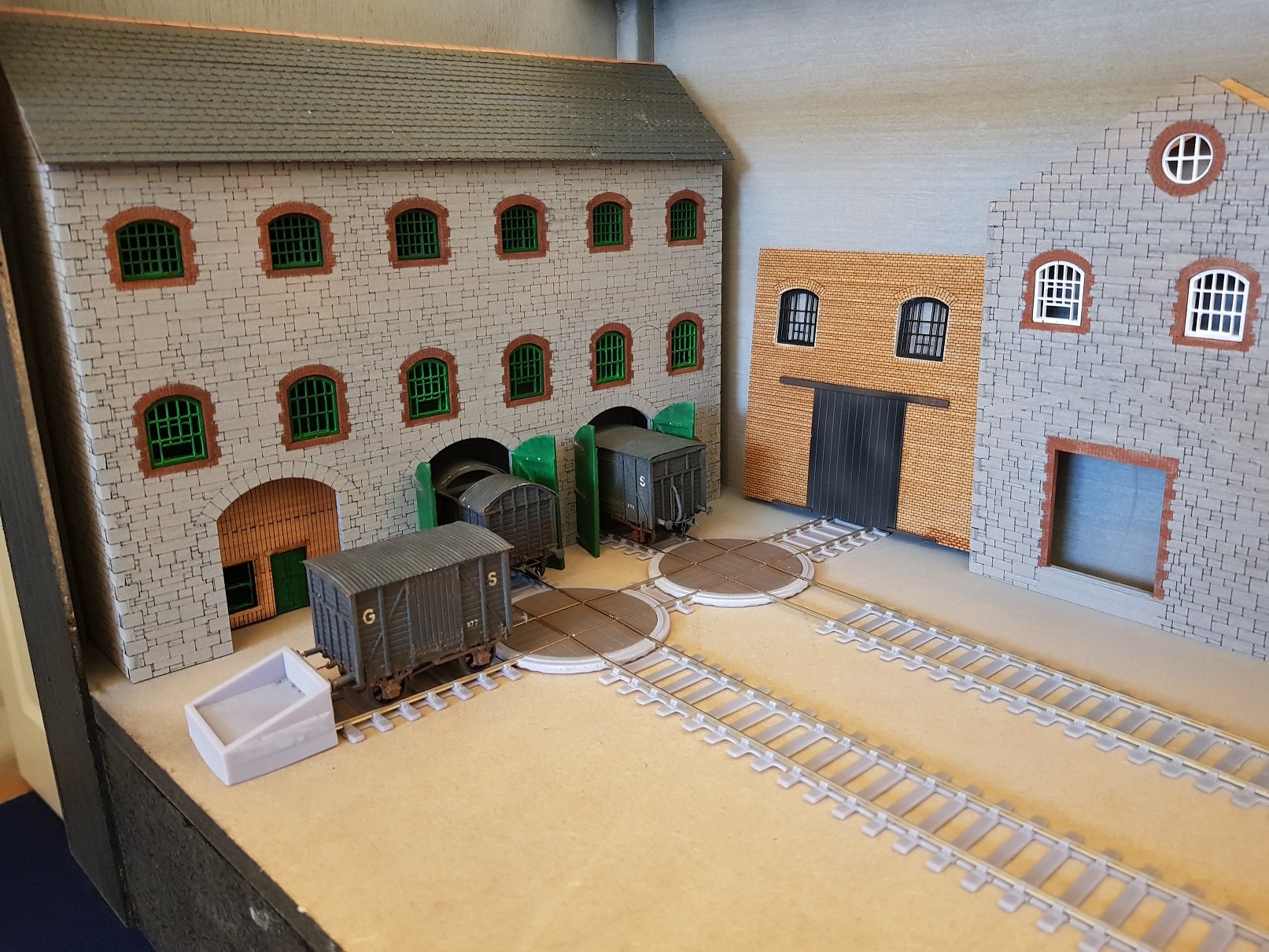
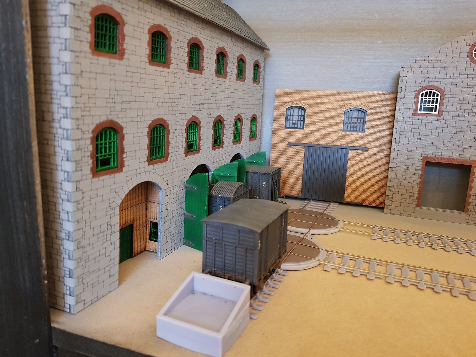
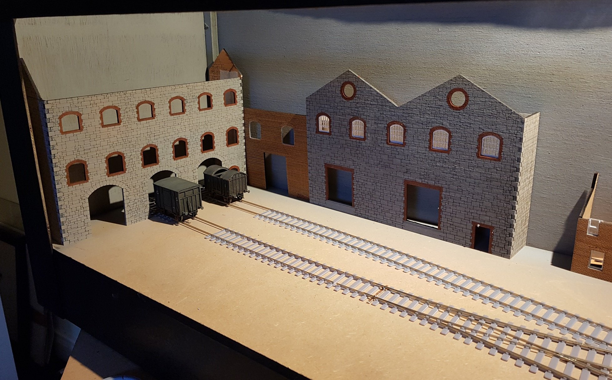
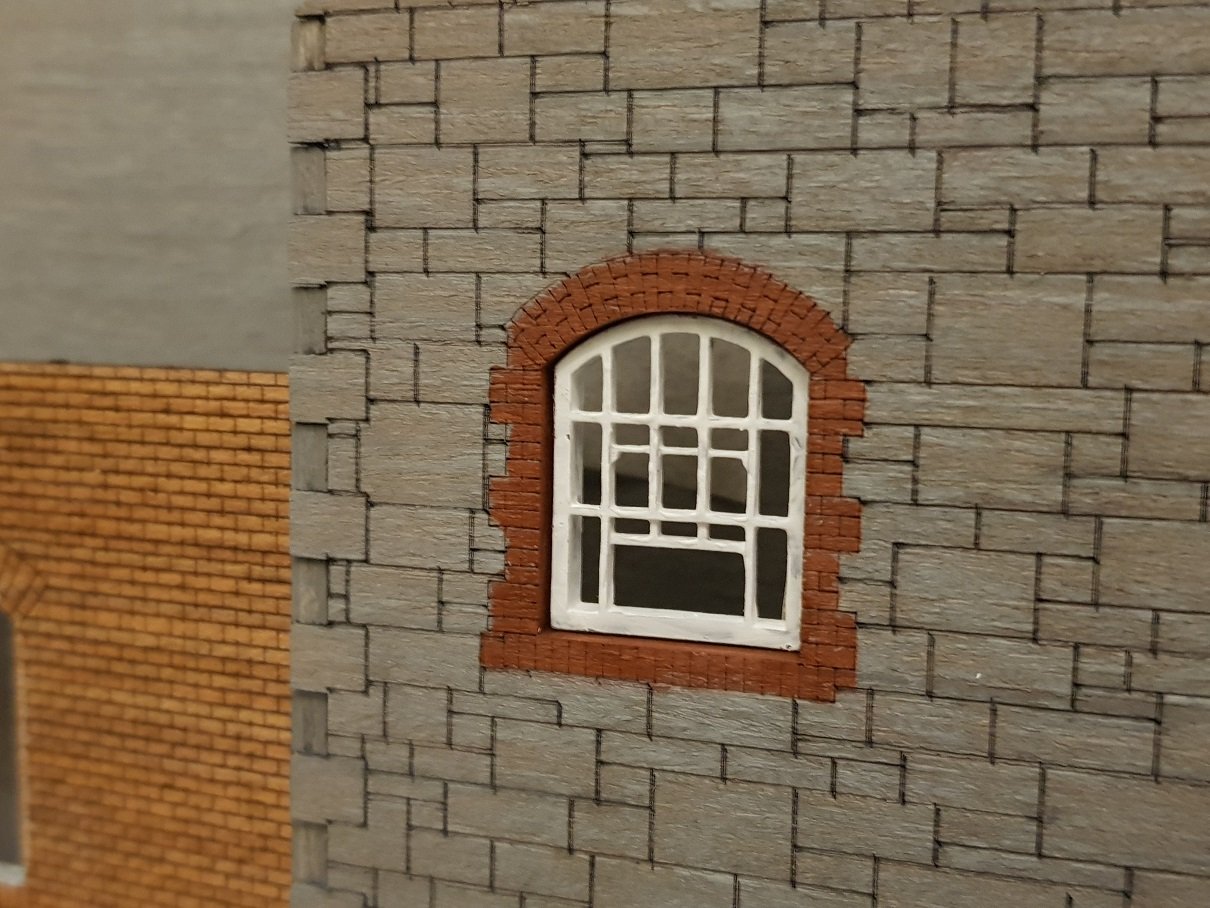
Thanks for the comments guys, much appreciated. Some good progress made on both the buildings and installing the turntables. Holes were drilled in the baseboards to take the turntables and also to allow point control - pipes and wires have been installed for point control, but the final connections need to be made. Turntables home, but not fixed yet; I want to use the cobbles to set the final positions prior to fixing down. All rails connected and wagons run in both directions, which was a pleasant surprise given the amount of time in design and construction. Windows and doors have been printed, painted and installed in the buildings - I still need to fill the panes with glue n glaze; this works well for these windows as they are quite small. The roof tiles are made from light card, painted and then cut into strips using the laser - strips then glued on in rows. I included a brewery office in the third arch - inspiration taken from a similar building in Guinness's brewery and provides a small focal point of interest. I may need to re-make the keg fab building (red brick building) as it is not quite filing the gap properly - it also needs some supports to ensure it stands on its own feet. Turntable base is slightly high, but this will improve once fixed down properly - there is also a slight ramp up onto the turntable deck, again a function of the base not sitting level. Keg store has got window and door, however I still need to get to the roof. The plan with this building is to have a platform in front with a roof over - the lines on the building indicate the position of the future roof. The main office building has got a roof - that valley at the roof intersection took some time, but turned out reasonably well. This roof used the same tiles as the main brewery building stepped to make the valley joint. I re-cut the loco shed as I felt the boards on the original were too wide; the revised cut looks a bit more realistic. Windows have been added while fascias need to be added to finish the roof. I plan to paint/dry brush this building to give a hint of paint and lots of wear with the boards & joints showing through. Anyway, all for now - more as progress warrants. Ken
- 16 replies
-
- 14
-
-
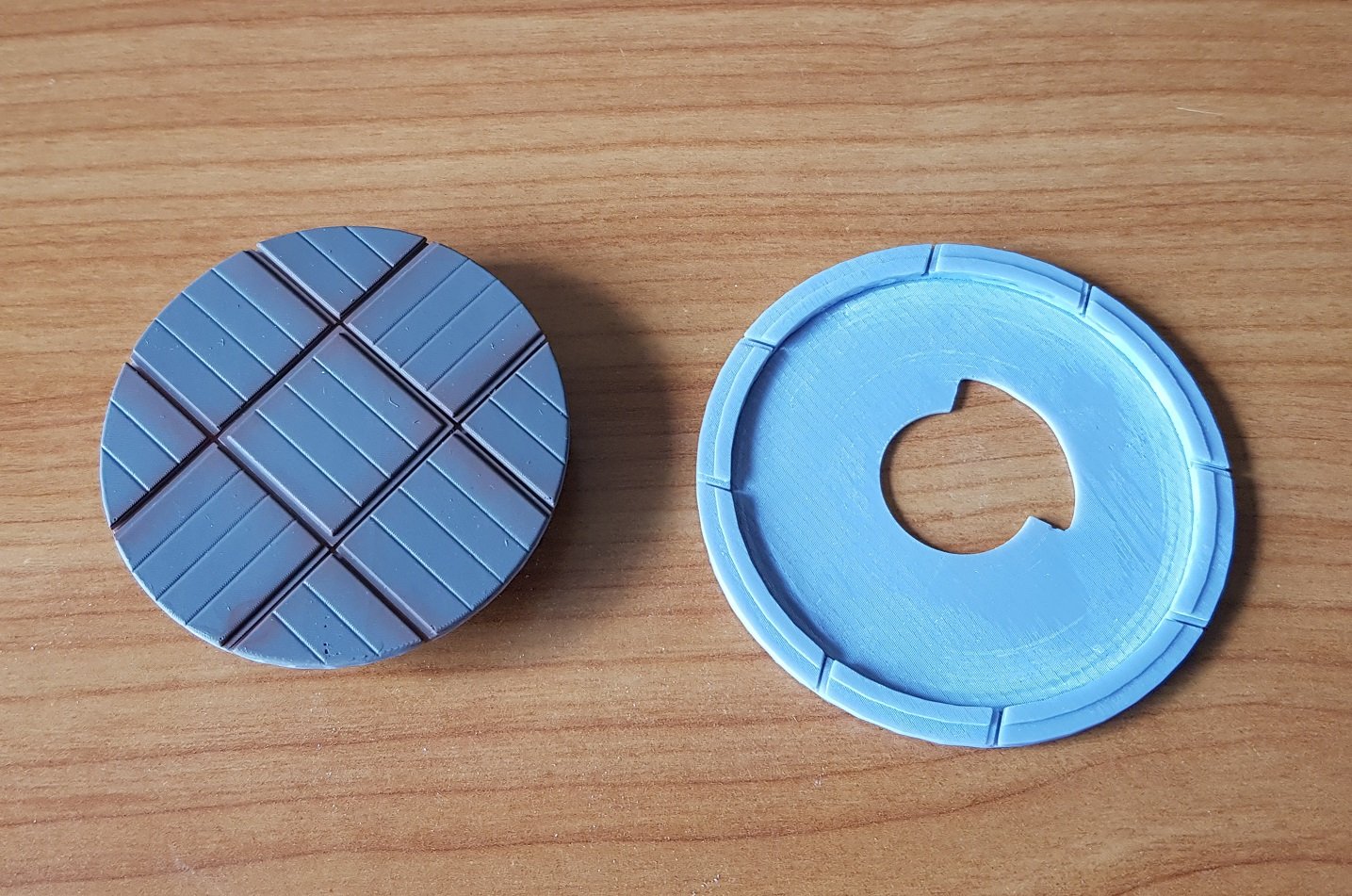
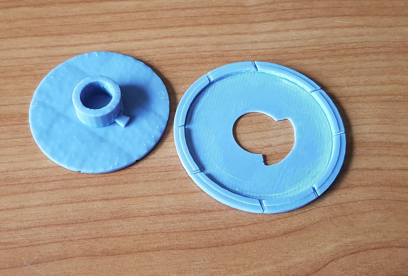
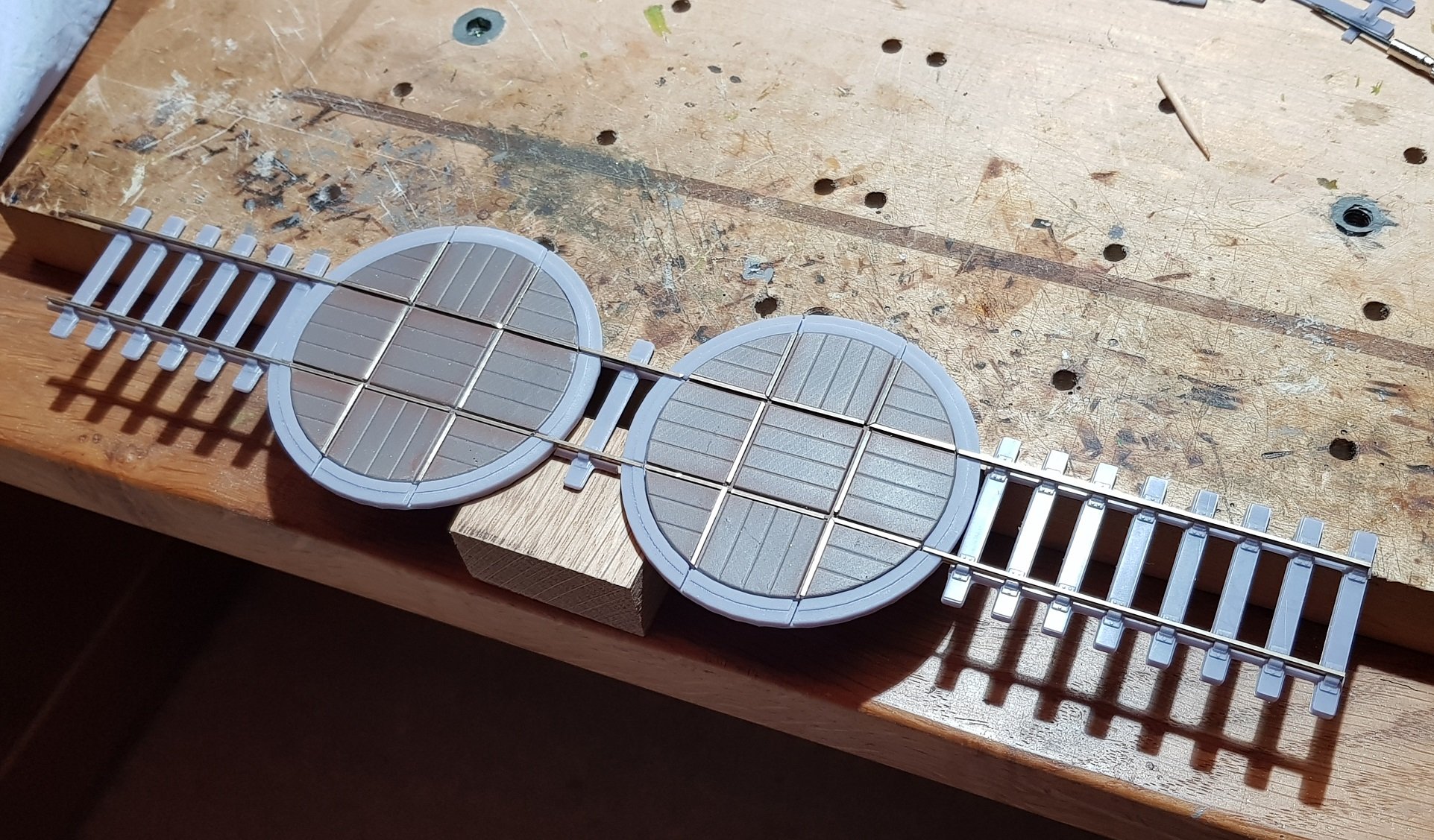
Finally got the printing of the turntables sorted, so I'll continue with two as originally planned. Tolerances are quite tight & material thickness is quite slim but with some fettling they appear to be working. The design allows for 90 deg turn only to be easier to control and get track to line up - what will be more difficult is how I can remotely turn them, but that's a problem for later. The column below the table will allow extension below the baseboard thus allowing connection for remote control. Underside of turntable deck needs a bit of tidying up to remove the printing supports while the cut out in base needed some minor filing to ensure turntable operates smoothly. Lots of track cutting and filing to get to the finished deck and track laid in one direction. I need to drill holes in the baseboard to inset these into the layout which will allow track connection in the other direction. I'll follow up with some more photos as I make progress. All for now.... Ken
- 16 replies
-
- 12
-
-
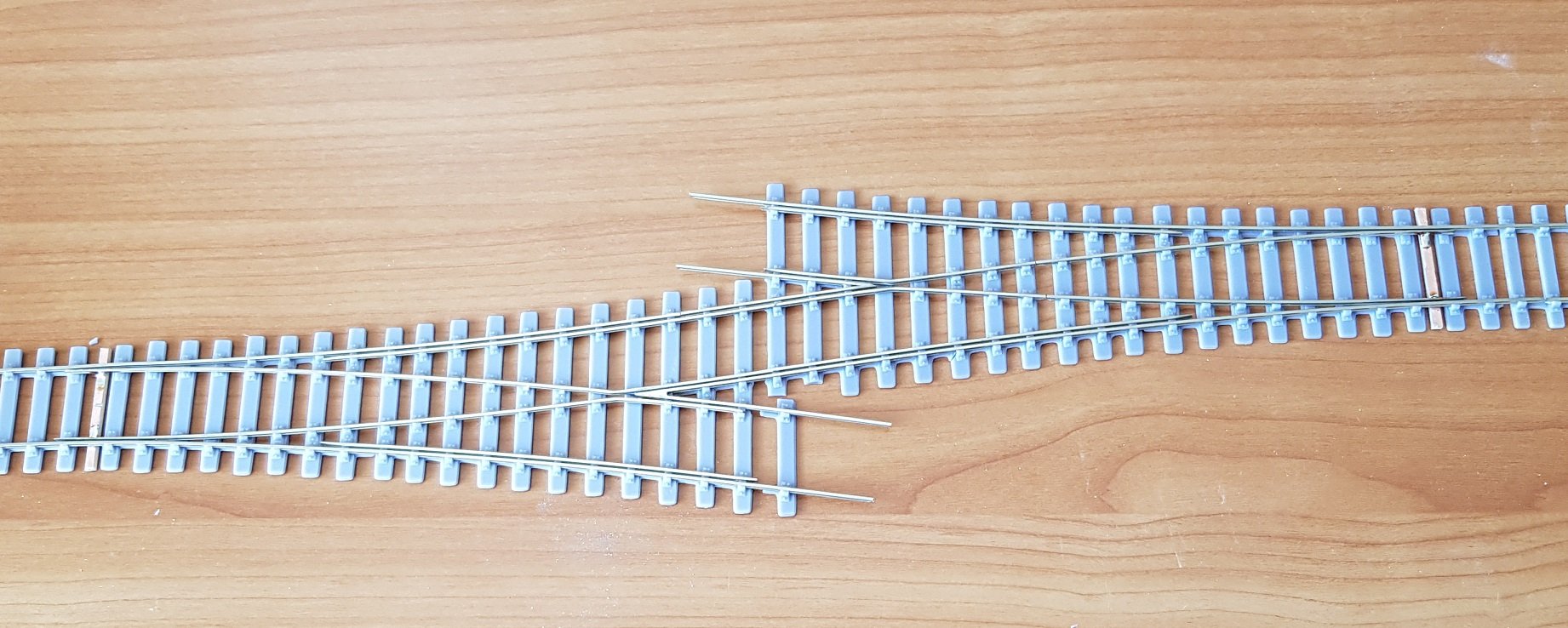
So points completed as a unit, which have turned out quite nicely - a prototypical look which is good. Time to check fit the points with the rest of the track - sans turntables for the moment. Turntables are in the process, but are taking some time to get the tolerances correct, but I'll get there. Opportunity to get point actuation installed - these will be push rod type control as there are only 2 points & the layout is small; no need to complicate things. More as time permits. Ken
- 16 replies
-
- 14
-
-
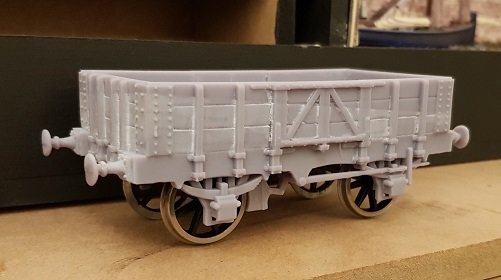
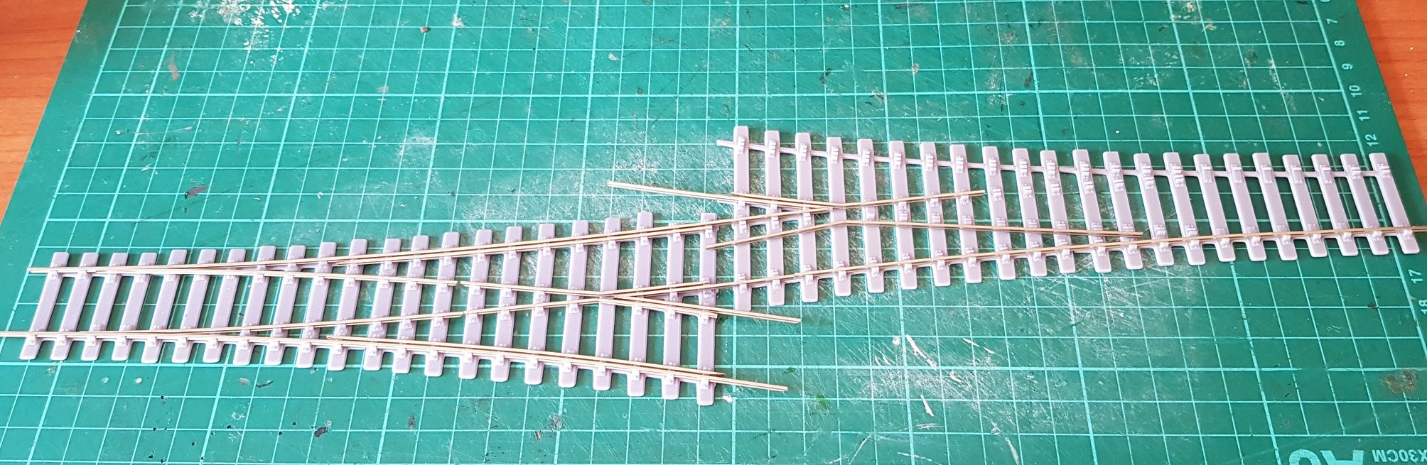
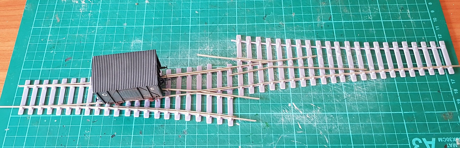
Time to get started on trackwork, well the points anyway. As noted above the plan is to use two Y points face to face with a short distance between the two. To do this I took standard Y points and trimed back the divergent lines to bring them closer together which means the exit of one flows quickly into the second - almost easier to show than explain... The LHS point is virtually complete and the current job is the fabrication of wing / check rail on the RHS point. This one needs careful trimming, the plan being to have the check rail run from one point right through to the second without break to give a more prototypical look to the whole installation. Rather than two separate points, this will be one large crossover smoothly flowing across - well that's the plan! Construction is 3D printed track bases with code 75 rail trimmed and filed as necessary. With this type of construction, I will only need one solder point at the crossing vee, however a lot more work to be done prior to making that solder joint. With the fine tolerances and rail lengths it's necessary to keep pulling the two elements apart until all elements are complete. The soldering of the vee will be the final touch. Also needed is a trusted wagon to check vee & wing rails tolerances to make sure all runs smoothly. 3D printing makes sure back to back dimensions are correct, however wing rail position relative to the vee needs fine tuning to ensure smooth operation & the wagon is essential. All for now. Ken
- 16 replies
-
- 11
-
-
-
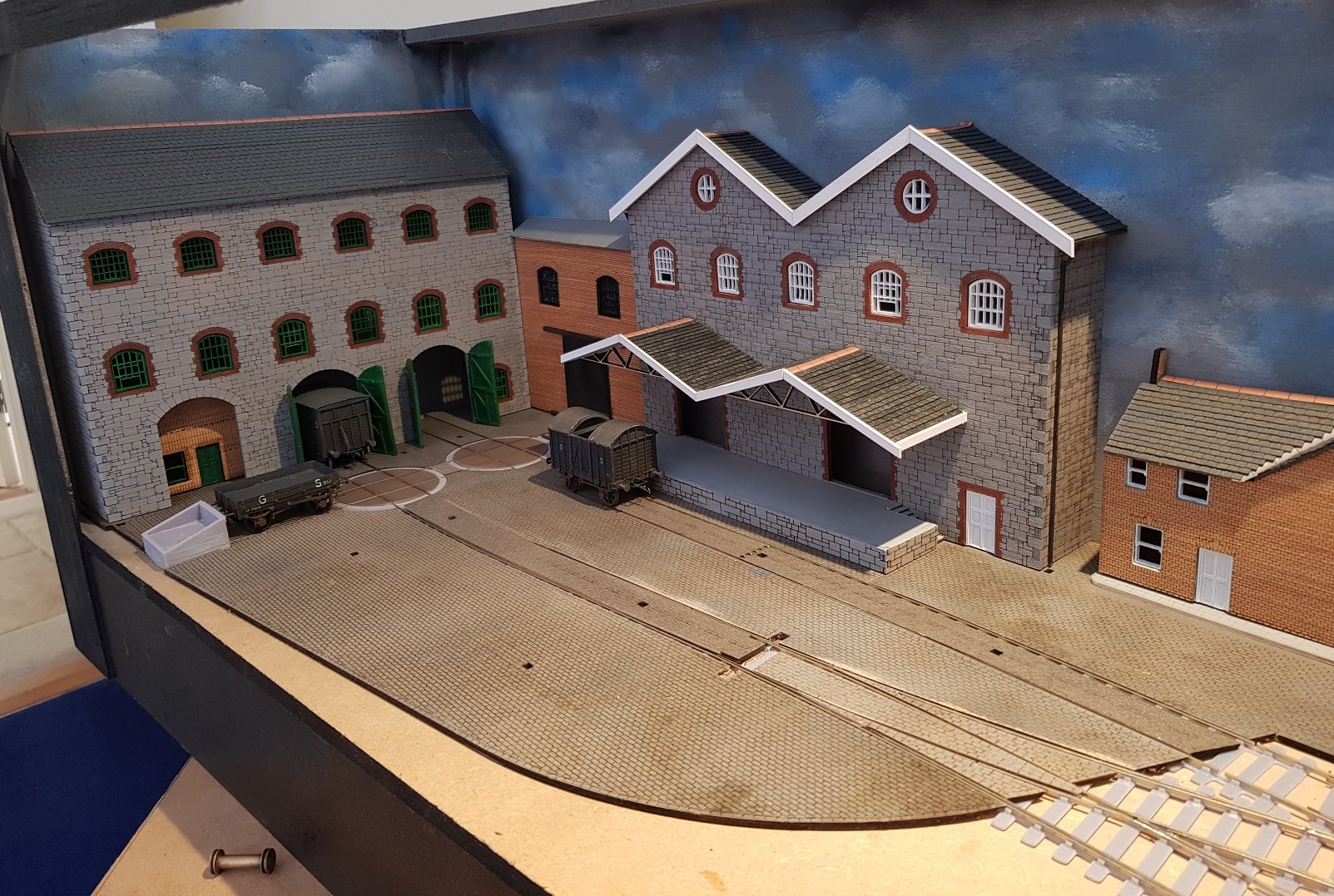
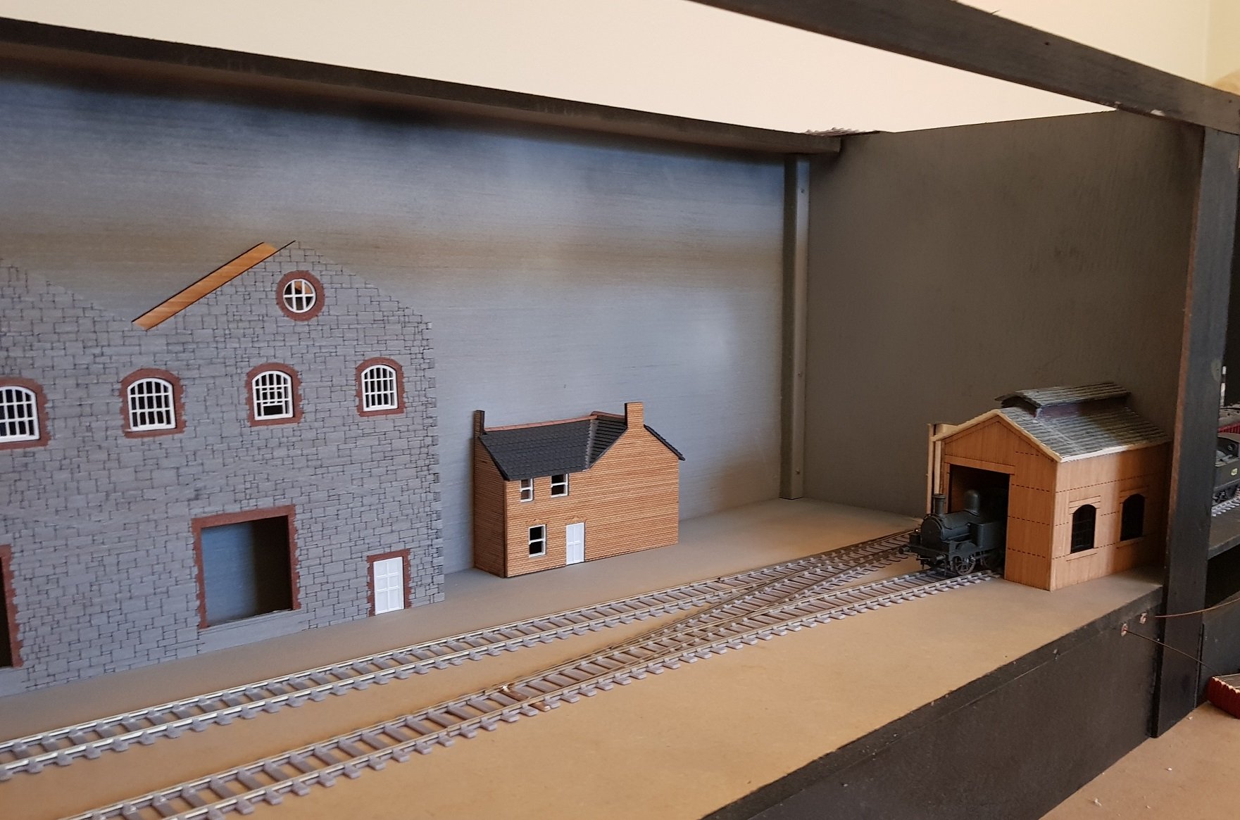
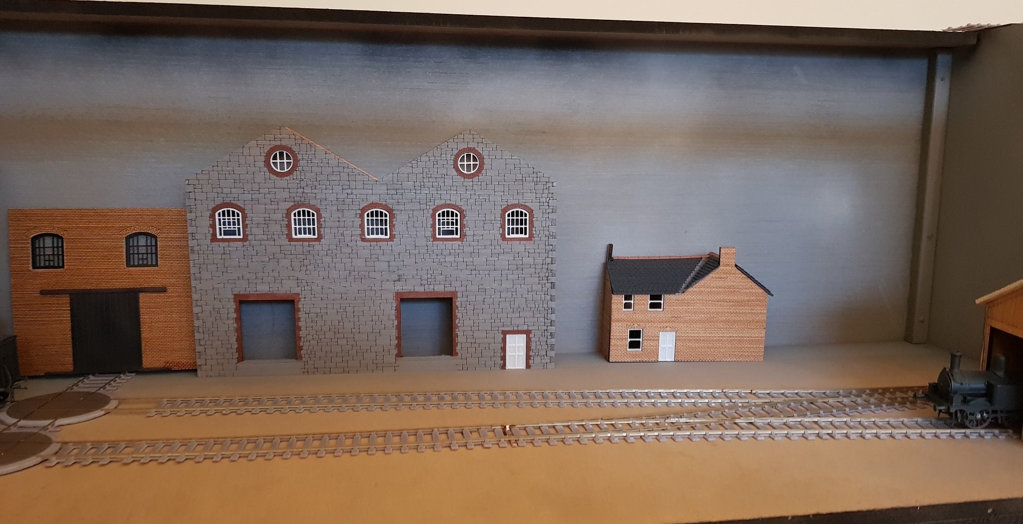
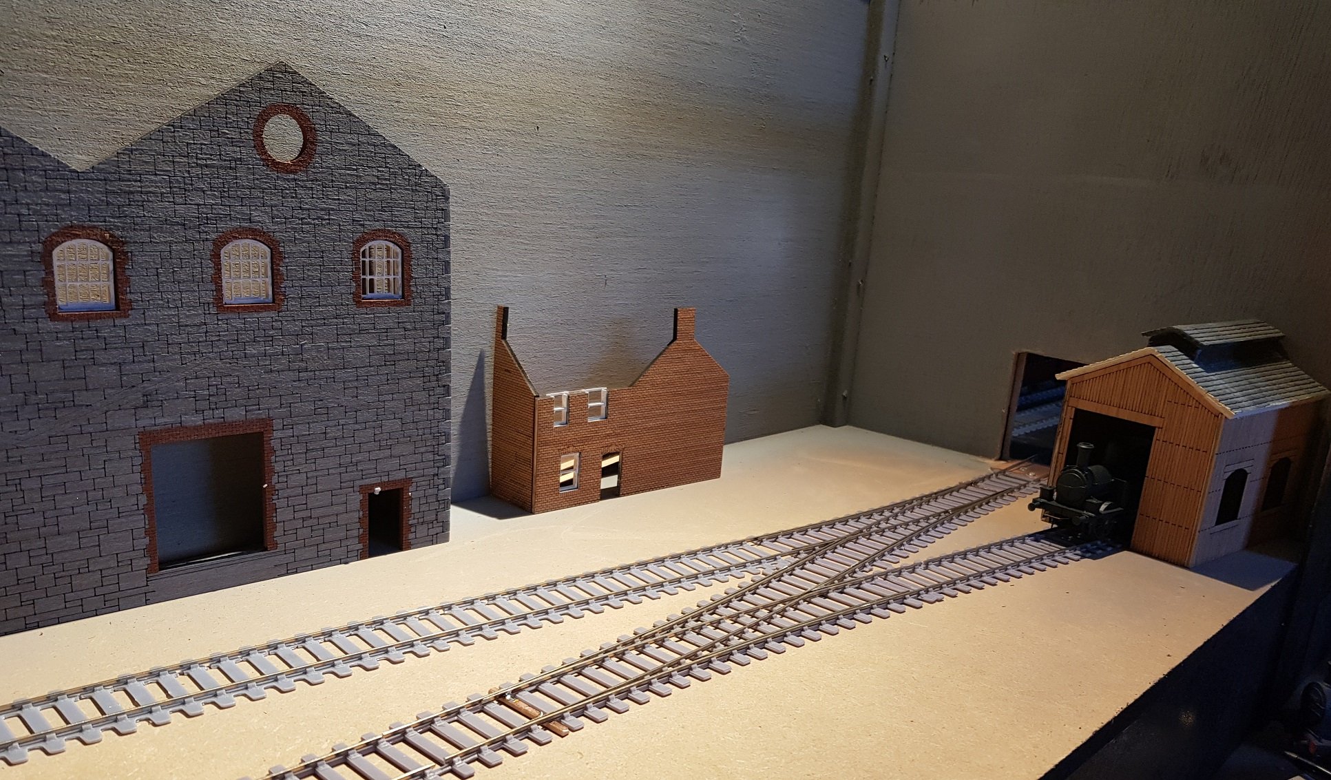
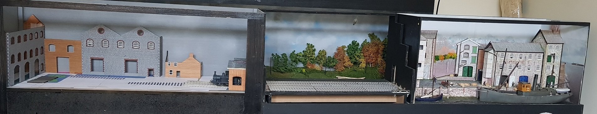
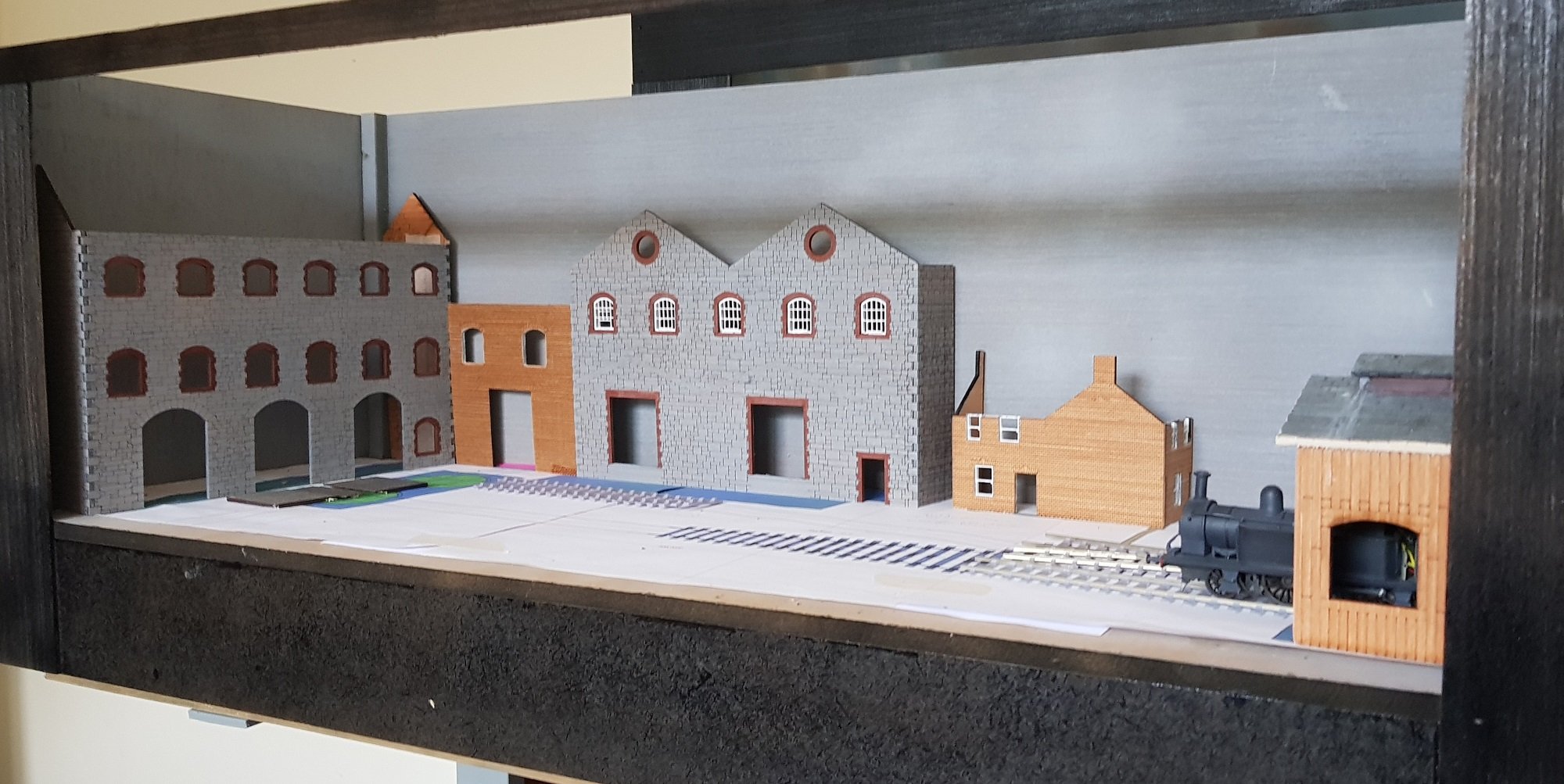
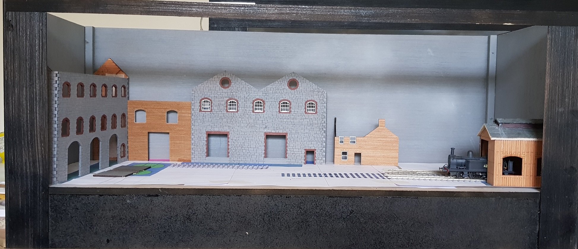
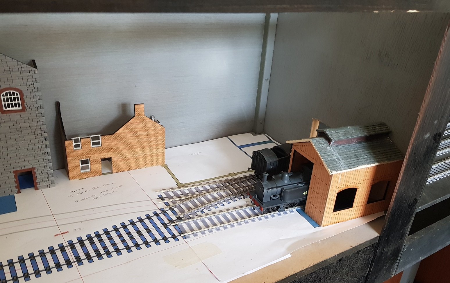
On a number of occasions when I had the Port Bréige model out on display some people asked if I was going to extend the model, in fairness, it is quite compact and not suited to large trains coasting about. My normal reply was that I did not intend to extend, as the only way would be out through the sector plate, and in keeping with the scene would end up with trains in the sea. However, it is possible to extend out through the other side of the sliding fiddle yard. So with a little adjustment a new layout is possible and it would be good to keep it in touch with the port layout. Given the port layout has a maltings facility, a small brewery makes sense - the bags of malted barley could be conveyed by train to the brewery and the completed casks trained back for onward shipment by sea! Again a fictitious layout, but as a simple cameo I think i can go with it. The layout will have two Y points, one on entering splitting the road, and a second facing the first allowing a short siding to a small loco shed; the intention being the brewery has its own loco for shunting work. I have 495 (a small Peckett 0-4-0) on the bench for change to RC, so once complete should be part of the loco power. I do have another Peckett body which I may make as a replica of the Guinness loco, but that's for the future. I am debating whether I will use one or two wagon turntables, one essential for delivering wood to the cask manufacturing building, while the second would be in line and allow a perpendicular line in front of the brewery building. Still not decided, but it is coming time to make that decision & get on with it. So how does it look? This is how the layouts combine together - with the cover on the sliding fiddle yard, there will be a clear distinction between the two. Brewery is bolted to the end of the fiddle yard which is where the break is for movement - the combined length being just over 2 metres long. Layout with buildings thus far. Loco shed being used as a view blocker for the incoming traffic. Roof is a repurposed one from another model scrapped some time ago. Buildings are made from 3.3mm plywood (4mm according to the hardware store) with the laser providing the details; windows being 3D printed to suit the openings. I would like to have a cobbled area in front of the main brewery & kegging buildings and am trying out an option with laser etching & cutting. If this works, I can integrate the tracks with the cobbles, rather than fixing the track and trying to get the cobbles to conform - jury is out on this one, but hopefully it will work. Still a lot of work to be done and a sky background would go a long way to develop the scene. Early days, but satisfying progress thus far. More as time permits. Ken
- 16 replies
-
- 14
-
-
-
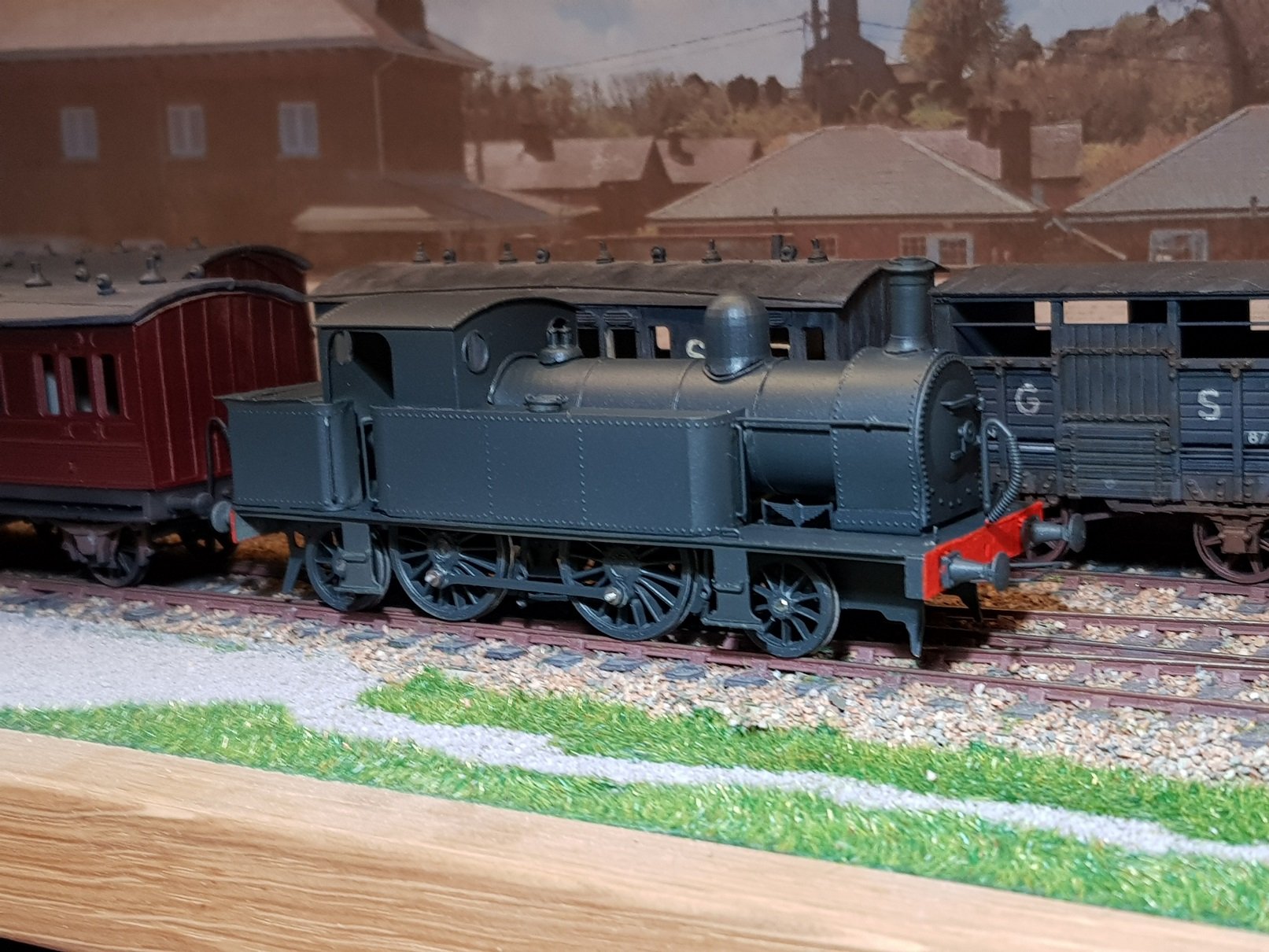
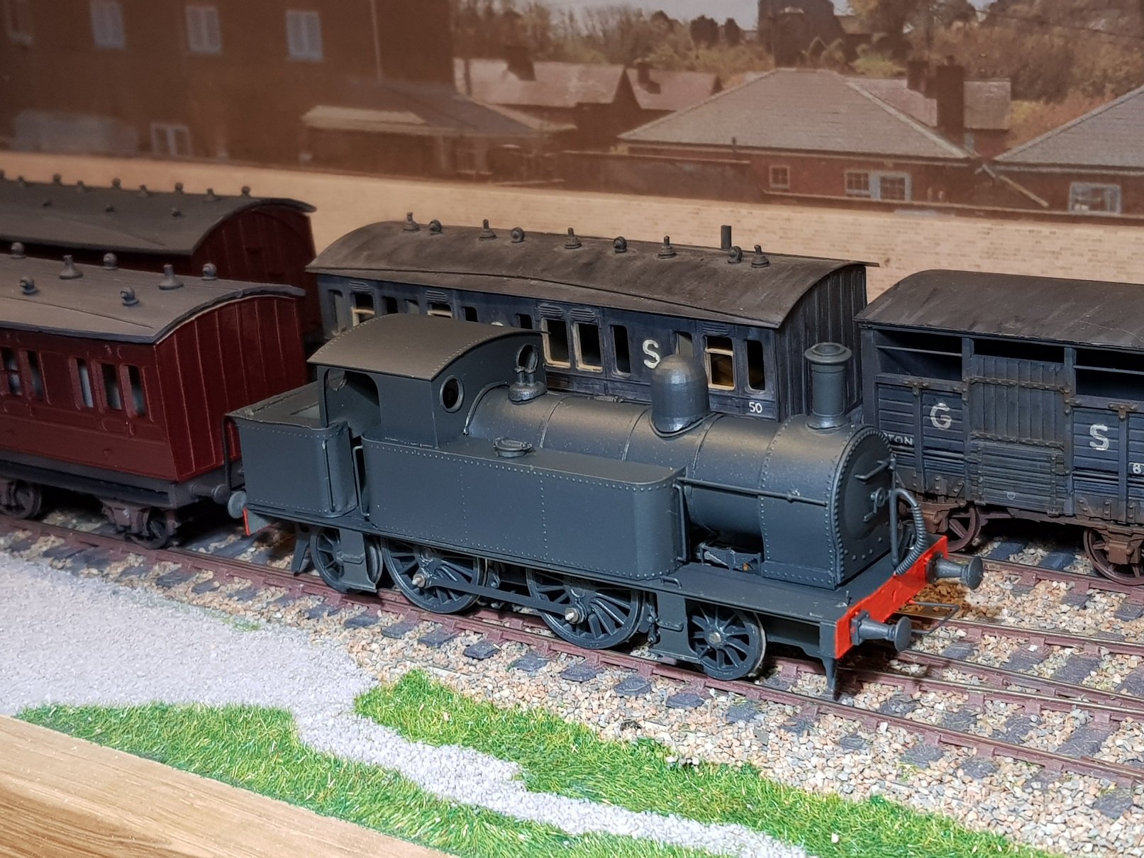
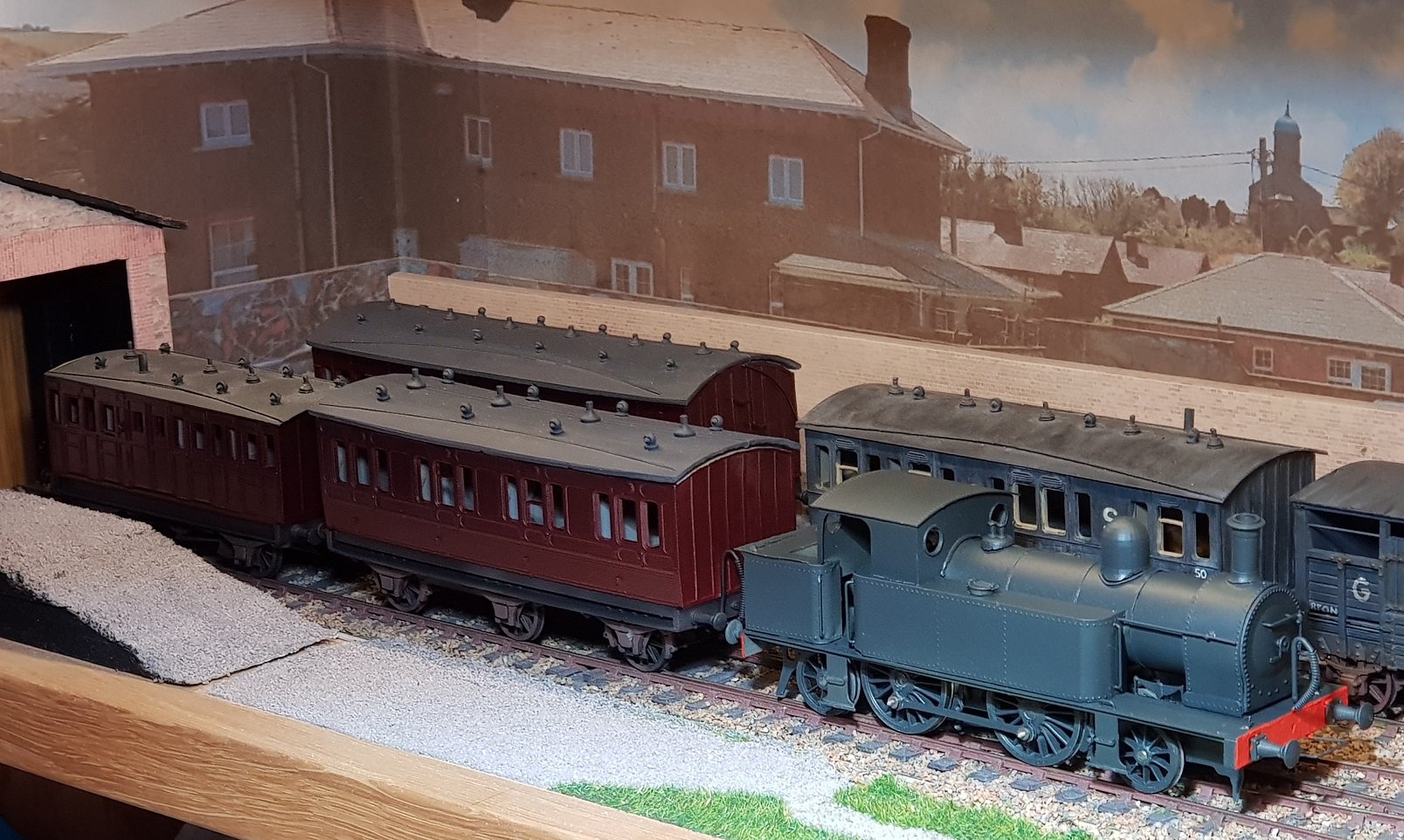
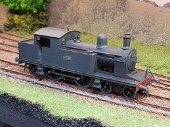
After some time in the paint shop...... And in line with some coaches for perspective..... Still a little bit of tidying up to do, but for now it can sit on the workbench test track. Still a very slight binding on the drivers, so that will need some fettling to get smooth running. I also need to tweak the receiver frequency as the motor is a little sticky at low speeds. Not often we see a pristine steam loco, so some weathering will be needed so it doesn't stick out too much!! All in good time.... Ken
- 379 replies
-
- 23
-
-
-
While I wait for transfers for the coaches, I needed to have some locos to pull them, so set to adding detail to 428. Handrails, vac pipes, tank fillers, etc all added which help bring the model alive. Still some tidying up to do - the dome is not sitting correctly and needs a skirt to finish it. Also there is space under the smokebox that needs to be filled along with the gap at the rear of the cab. Little things, but they do take up time to set right and then off to the paintshop for a coat of grey. All for now. Ken
- 379 replies
-
- 17
-
-
-
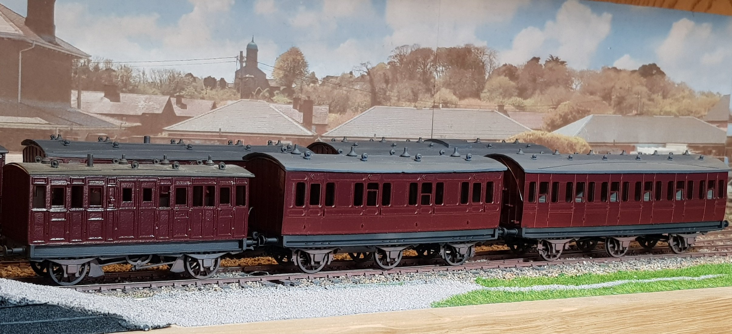
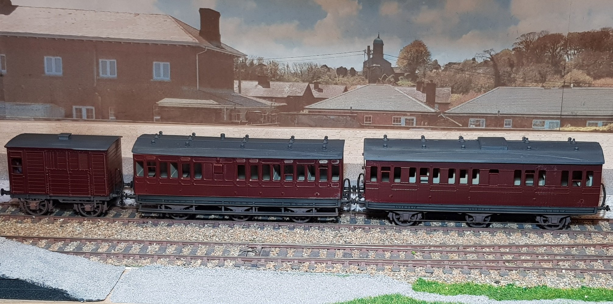
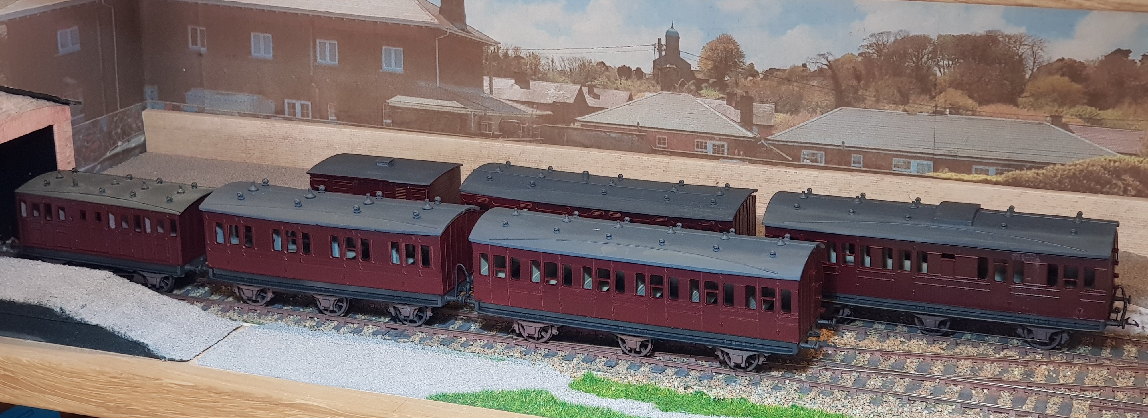
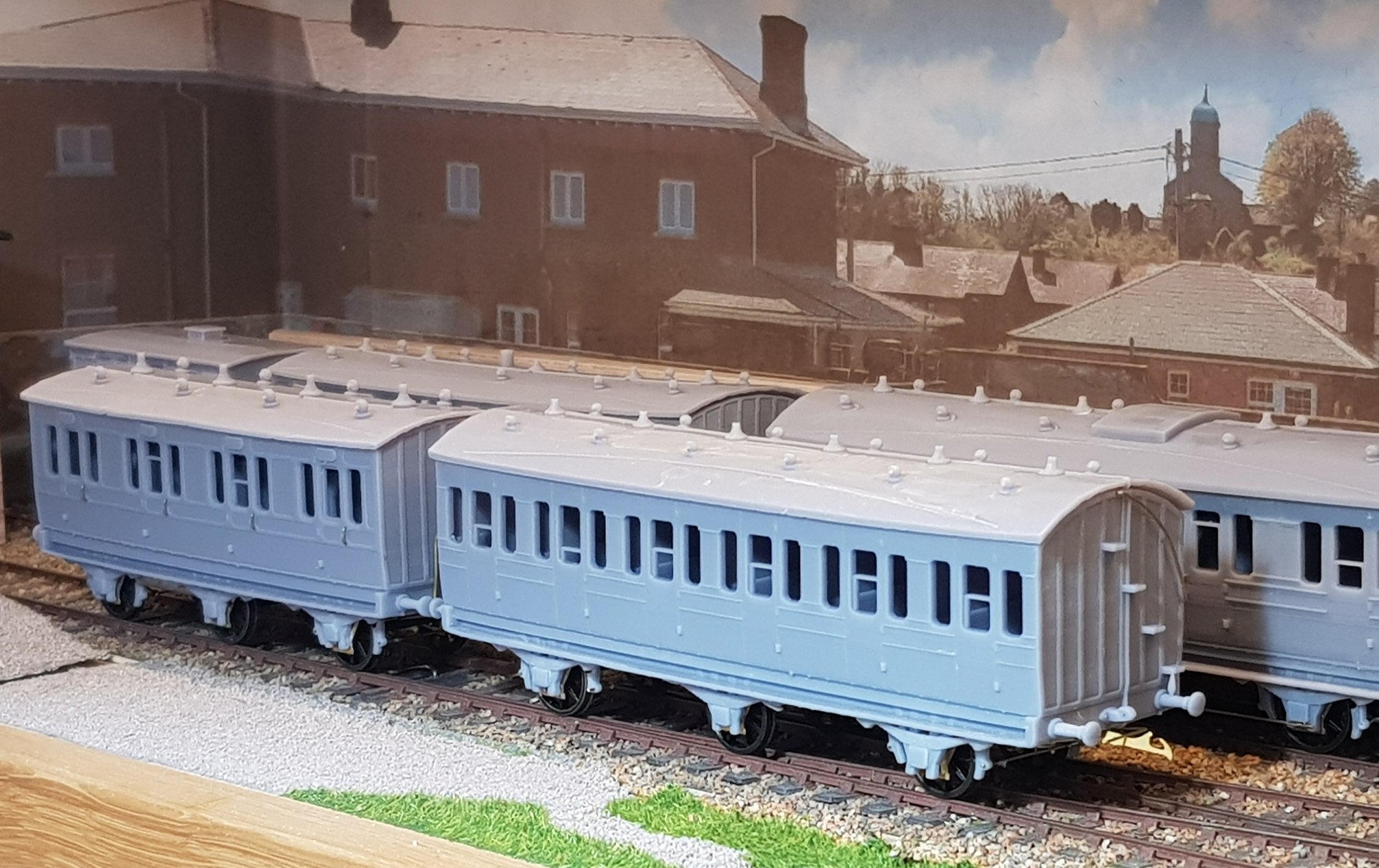
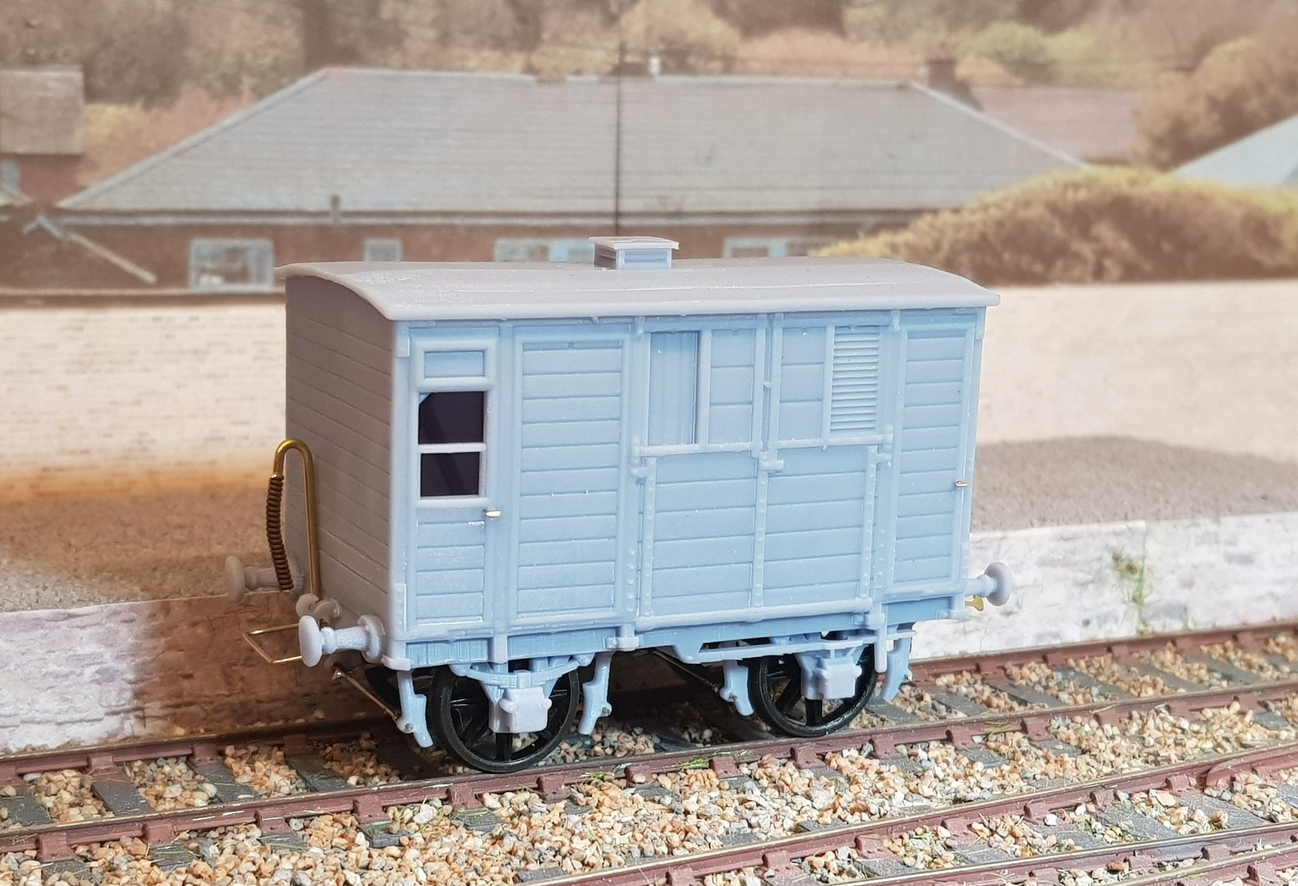
Coaches are back from the paintshop. First up, 21'6" Metropolitan 4-wheel Third Brake (No. 63), with 28' four comp First (No. 48), and 34' six comp Third (No. 46) Next Up; DSER Horsebox, with 31'5" four comp Third Brake (No. 70), and 34' 1st/Lav/3rd Composite (No.30). Busy Terminus! All are up for lining, numbering, door handles, grab rails and glazing; may consider some passengers if I get the time and inclination. More as time and energy permits...... Ken
- 379 replies
-
- 19
-
-
-
Superb work Alan, and very well executed. For my Peckett project (495) I used the cylinders and gear from a shop bought version which I will now need to modify as the model is getting Alan Gibson spoke wheels which have a much smaller crankpin than the original - I'm sure I'll come up with something, but I rather like your idea. Ken
-
Certainly for the models I'm showing above, they are correct compared to drawings and photos of the prototypes. From my research it appears quite a majority of coaches did not have the lower steps; trawling through photos and drawings so far I'm finding probably only 40% of DSER coaches had lower steps. I wonder perhaps is it a result of most of these coaches being used on the Harcourt St - Bray and Westland Row - Bray lines in scheduled commuter traffic through stations with full platforms? Ken
-
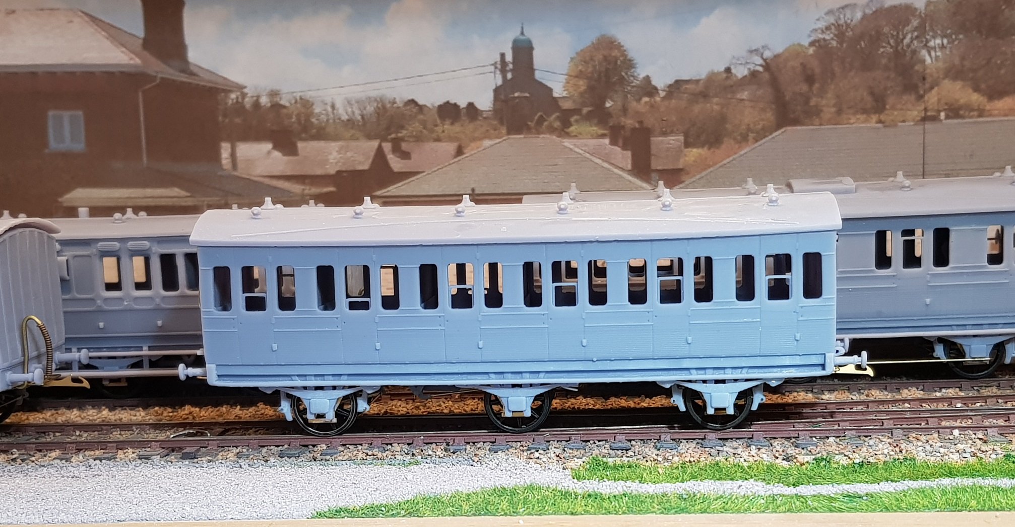
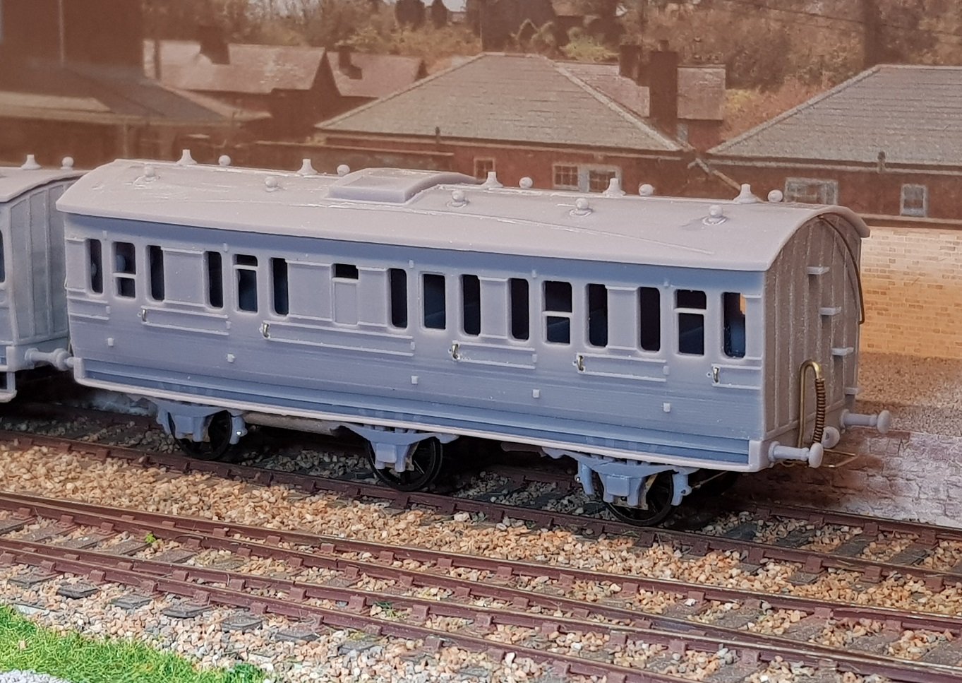
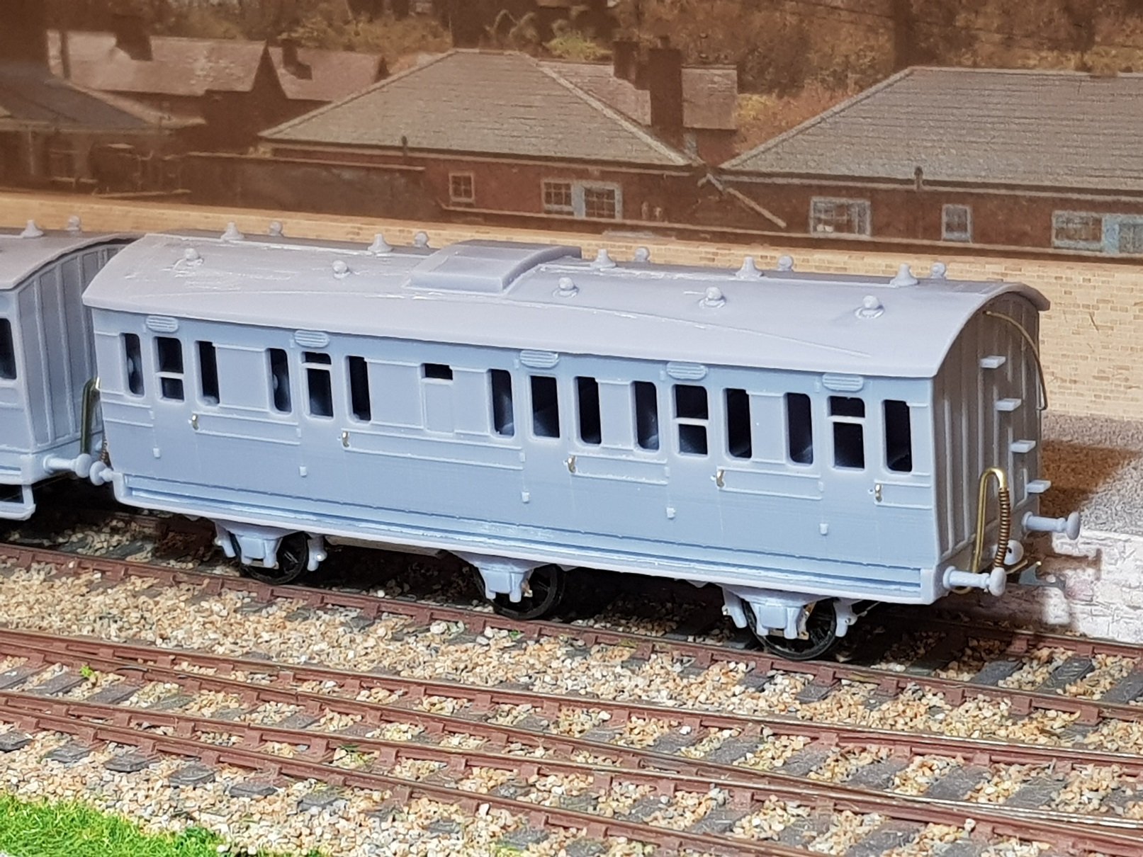
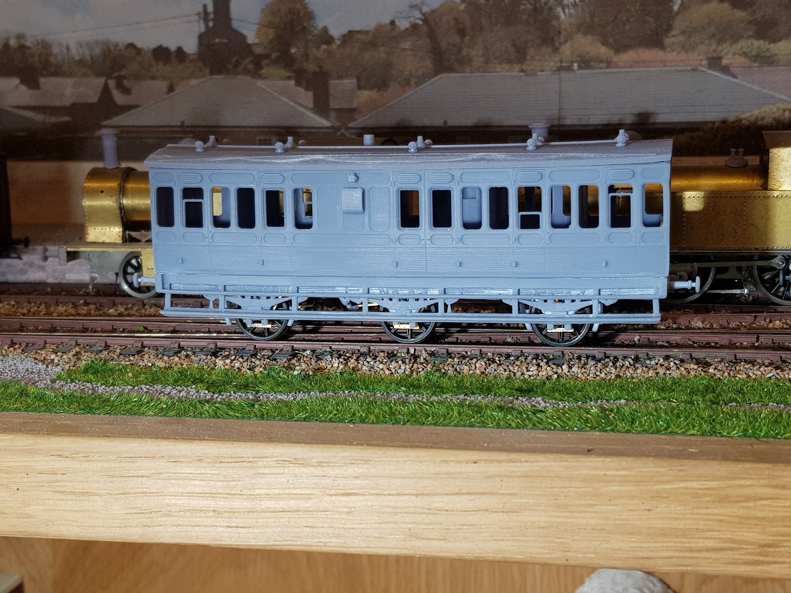
As the 1st/Lav/3rd was a 34' coach built in 1907, the chassis and basic design was also suitable for No. 46 a 6 comp 3rd built in 1906 (withdrawn 1955). Both coaches were built in the Grand Canal Works and it is easy to see the commonality between designs in terms of roof pitch, side panelling design, no over door louvres, etc. Thus the evolution of No. 46 from No. 30 was quite straightforward Panelling detail of 46 and 30 in the background right can be seen to be similar, so obviously no great rehashing of designs around the period! No. 46 in company with No 48 4 Comp 1st (28'). The roof profile is quite distinctive between the two showing what most consider the "DSER" roof profile, however I have found through my research that these high roof coaches may be in the minority - most coaches appear to have had the lower roof profile similar to other railways. Anyway, No. 46 still needs a few final attachments prior to painting such as the vacuum pipes and door grab rails. The roof needs quite a bit of tidying up as there was excess resin overspill which has left some material to be removed, but not a major hassle - easily taken off with a scalpel. The plan would be for 46 to form part of a mixed branch line train with some goods wagon and a goods brake, pulled by what loco, we'll have to see later. All for now, still a bit to do before these coaches get to the painting shop - not all will be GSR, some will be in DSER livery, namely; No.48 plus its companions, No.1 5 Comp 3rd, plus the Metropolitan 4 wheel brake 3 (more later on those). Talk soon. Ken
- 379 replies
-
- 12
-
-
-
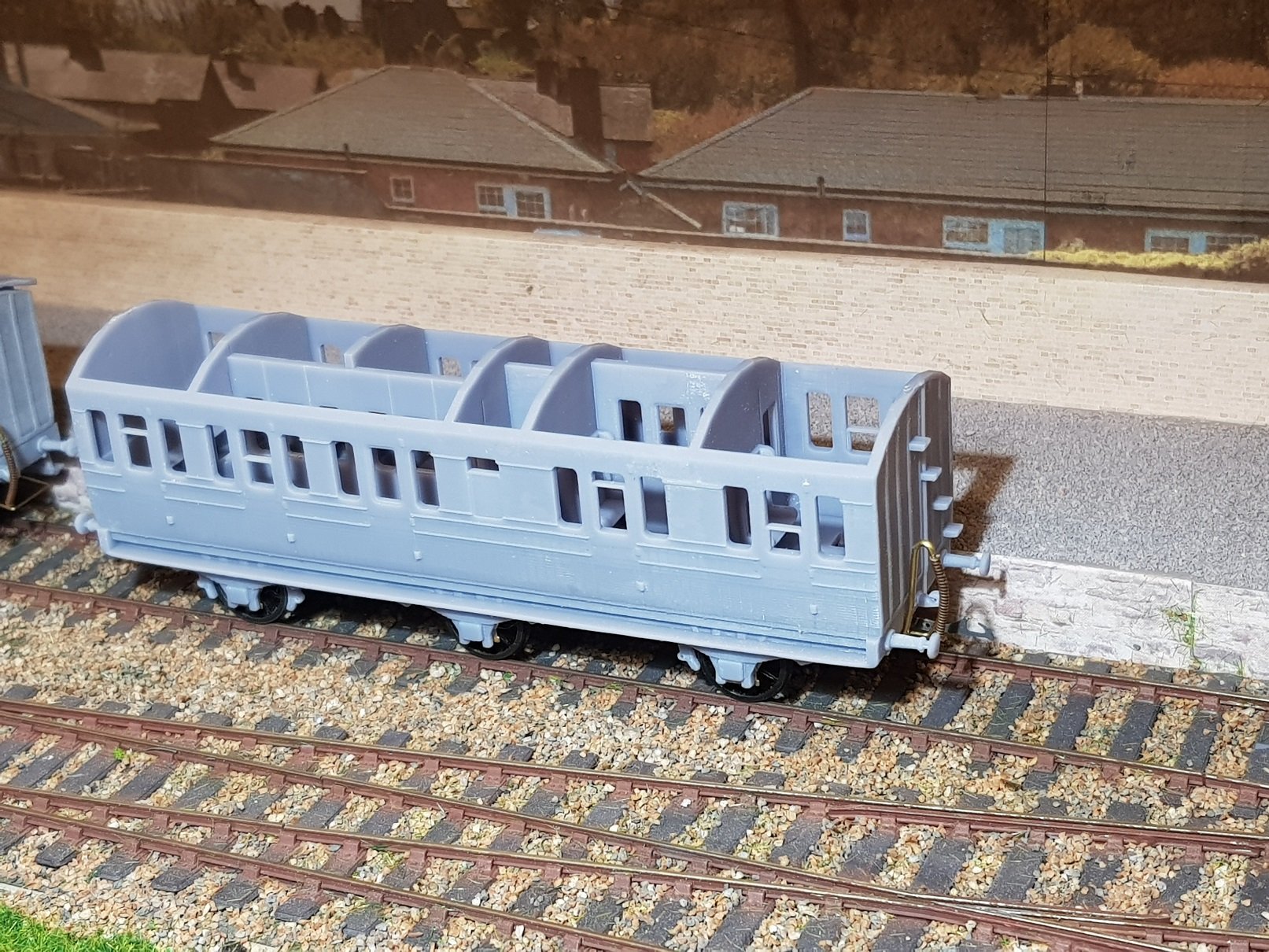
After a little diversion into 6 wheel coach interiors, I have revised the 1st/Lav/3rd which now has corridors to allow all access to the toilets, so hopefully this is the last revision & I can get on with painting. The longitudinal partitions do not reach up to the roof level, as the roof includes stiffening elements which protrude down into the compartments, however with the roof on, this is not visible. There will be a lot of glazing to do once this has been painted, but that's for another day!! Ken
- 379 replies
-
- 12
-
-
Bob, Some nice ideas being teased out here, but for me you have solved a problem I wasn't aware I had. I have built/printed a model of a DSER 1st/Lav/3rd - No. 30D, and I was wondering how various compartments, excepting those next to the lav accessed it. This coach has 2 x 1st class and 3 x 3rd class compartments, so slightly larger than your coach at 34ft. Of course the answer is corridors, however I wasn't aware 6-wheelers had internal corridors, but your sketch makes eminent sense. You mentioned access to some drawings, if so, would you have an idea of the internal corridor dimension? It looks like I will need to re-model the interior and re-print, not a biggie, but it's worth the time to get it right! Ken
-
Seriously impressive models and modelling - a credit to you Bob. Let's hope we see more of them soon. Ken
-
Seriously impressive. Lining is one of those areas I try to avoid as much as possible which is why most of my locos are in GSR grey, with simple grey wagons. I do need to put some effort in though, and the intention is to paint my 2-2-2 in DSER colours and apply lining..........well, some time soonish!!!
-
Whilst the energy levels are reasonable, I have had some time to work on the coaches and horse box to make up my short branch train. The horse box got brake gear fitted, vacuum pipes, door handles, and couplings added to bring it ready for painting: The third brake also got some additional work to the chassis to include a gas tank, vacuum pipes, and couplings which also brings it ready for painting. Grab handles have been added, but door handles will be added after painting. It may be necessary to remove the grab handles when it comes time for lining, but time for that later. The 1st / 3rd Composite needed a reprint after discovering problems with the Mk 1 version. Some of the panelling was not present and the water storage tank for the toilet was not quite in the right place - some re-working of the 3D model and a re-print produced a much better model. I have added a chassis similar to that of the 3rd brake along with gas tank, vacuum pipes, end handrails, grab handles, and couplings bringing it too ready for painting. Painting all three together will hopefully ensure the train at least is the same colour! This all brings us very nicely to a branch line train with 1st and 3 accommodation with horse box in tow. Add to this loco 423 (still incomplete, but nearly there) and we get a nice short train the fits within my 500mm limit for traverser storage. I have limited traversers to this length as the layout I am building will not look right with trains longer that this keeping to the 1/3rd rule of train to layout. The roof of the 3rd brake still needs tweaking slightly to get it to sit properly - as goes for the cab roof of the loco.... So in unpainted condition we have: All for now and the next challenge is to get these through the painting shop without major difficulties - here's hoping!! Ken
- 379 replies
-
- 17
-
-
-
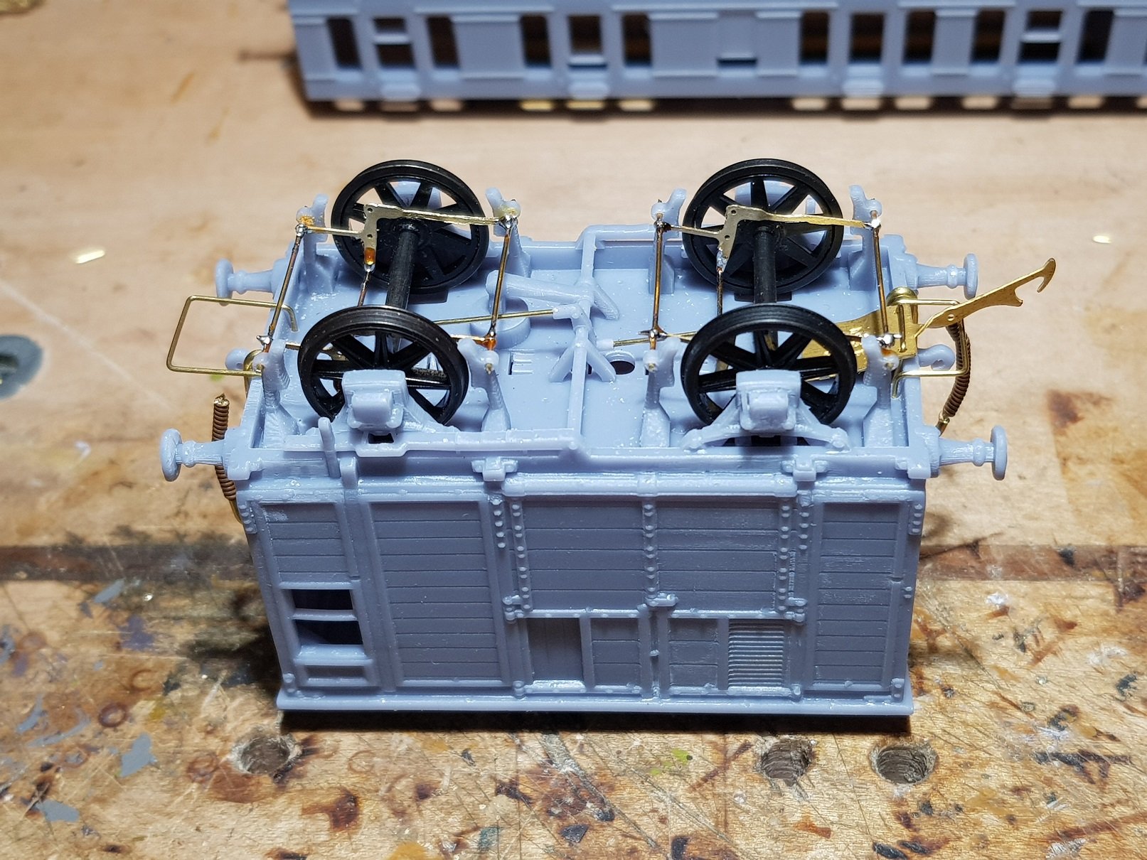
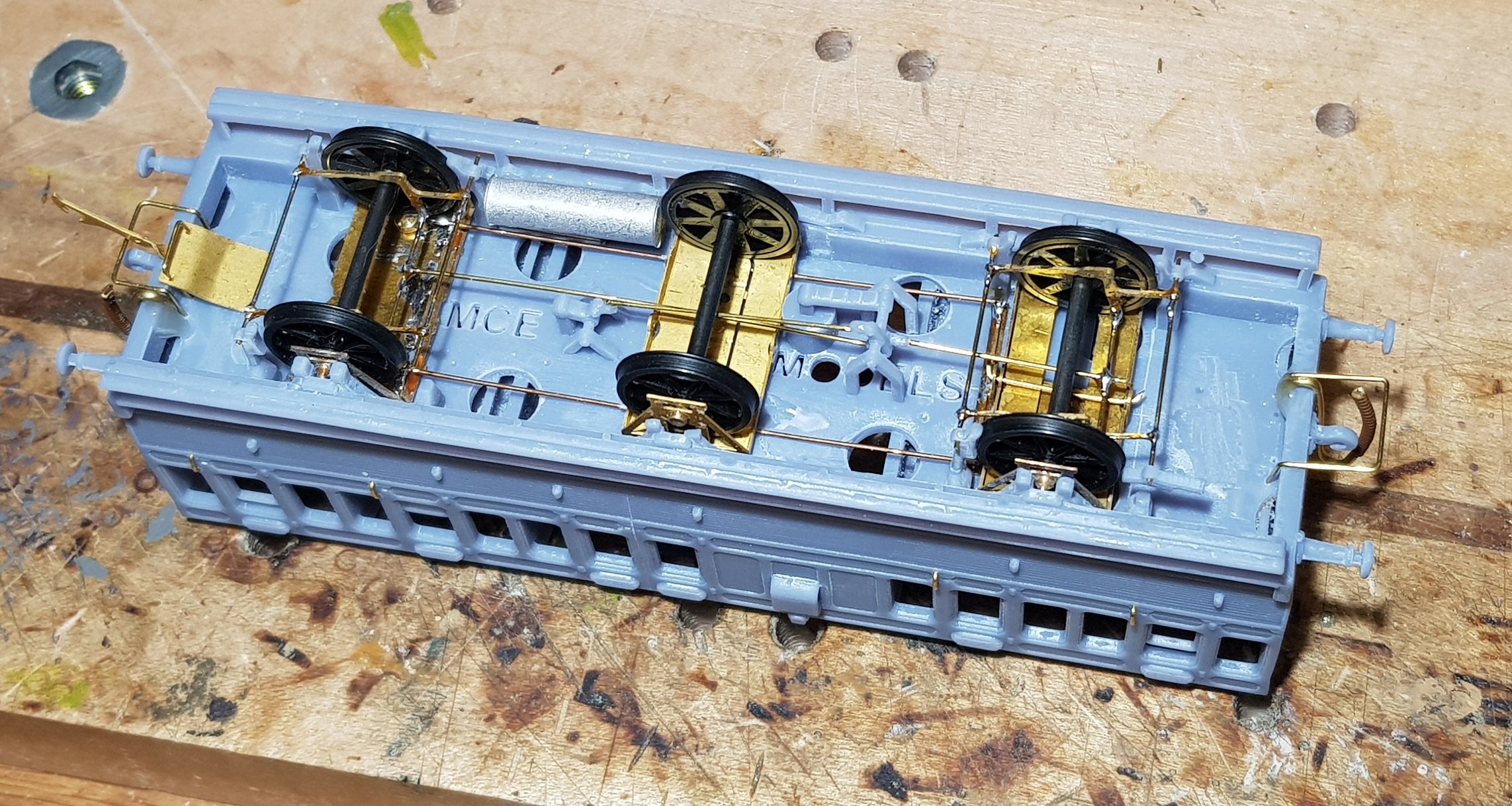
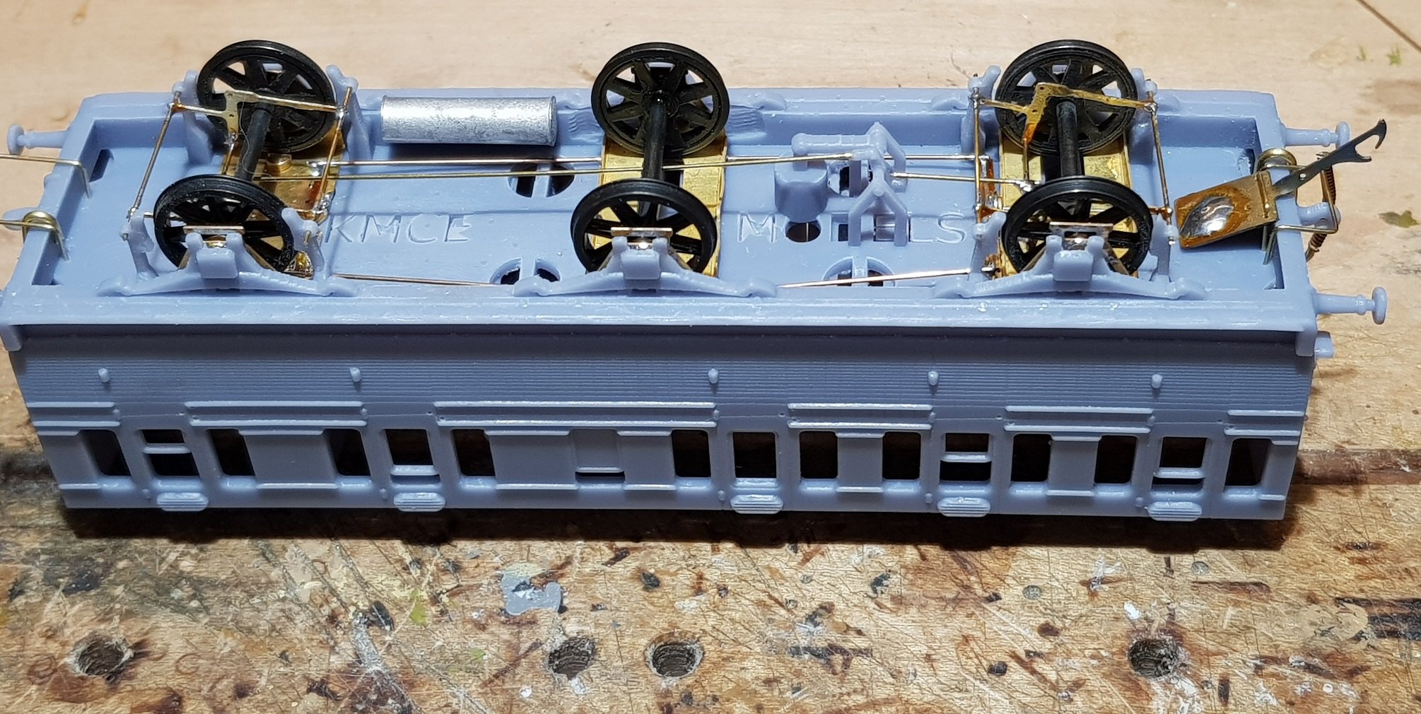
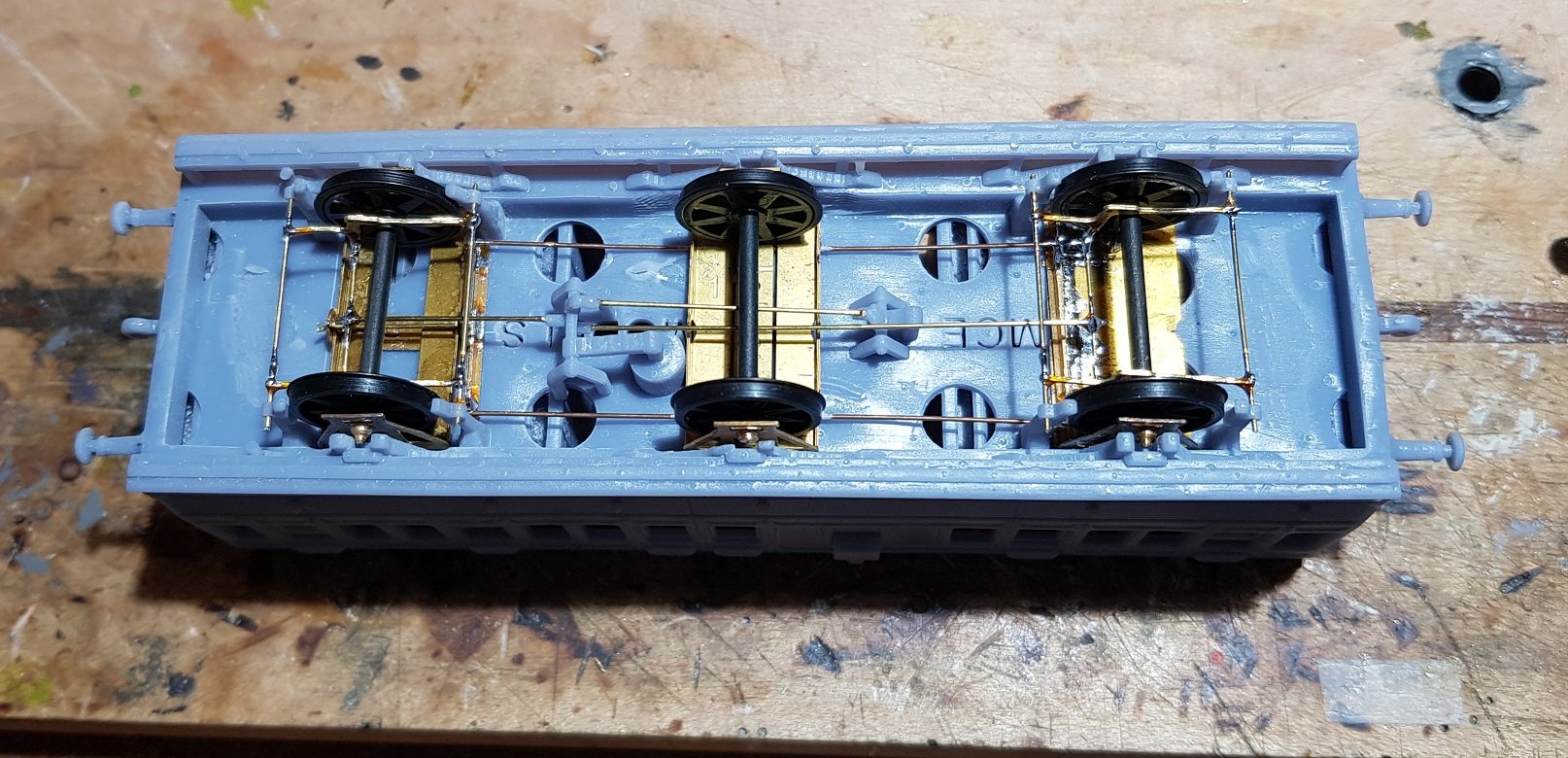
No - I use one and a half compensated wagon chassis kits as supplied by SSM. I have tried many variations of compensated chassis but have found this one to be the best; easy to set up and works every time. Challenge here was getting into the limited space between the frames - I had to beef up the frames to reduce the warping tendencies in the 3D print, which in turn reduced the internal space for the chassis. A little bit of grinding was needed to ensure both the rocking element and middle axle could move freely.
-
A little bit further on with the 3rd Brake coach. Got some time to squeeze in a compensated chassis with a floating centre axle - I may need to add a little weight to the centre axle supports to ensure it remains put on the rails when negotiating points, but I can get to that as required. Brake actuators were added along with the interconnecting rods to the printed brake equipment - easier to show than explain!! All tidied away nicely, and almost unnoticeable when the coach is the right way, but I know they are there! Brake hoses, couplings, Gas tank, door handles and associated handrails to be added, but coming together rather well. Anyway, all for now. Ken
- 379 replies
-
- 14
-
-