KMCE
-
Posts
540 -
Joined
-
Last visited
-
Days Won
29
Content Type
Profiles
Forums
Events
Gallery
Blogs
Everything posted by KMCE
-
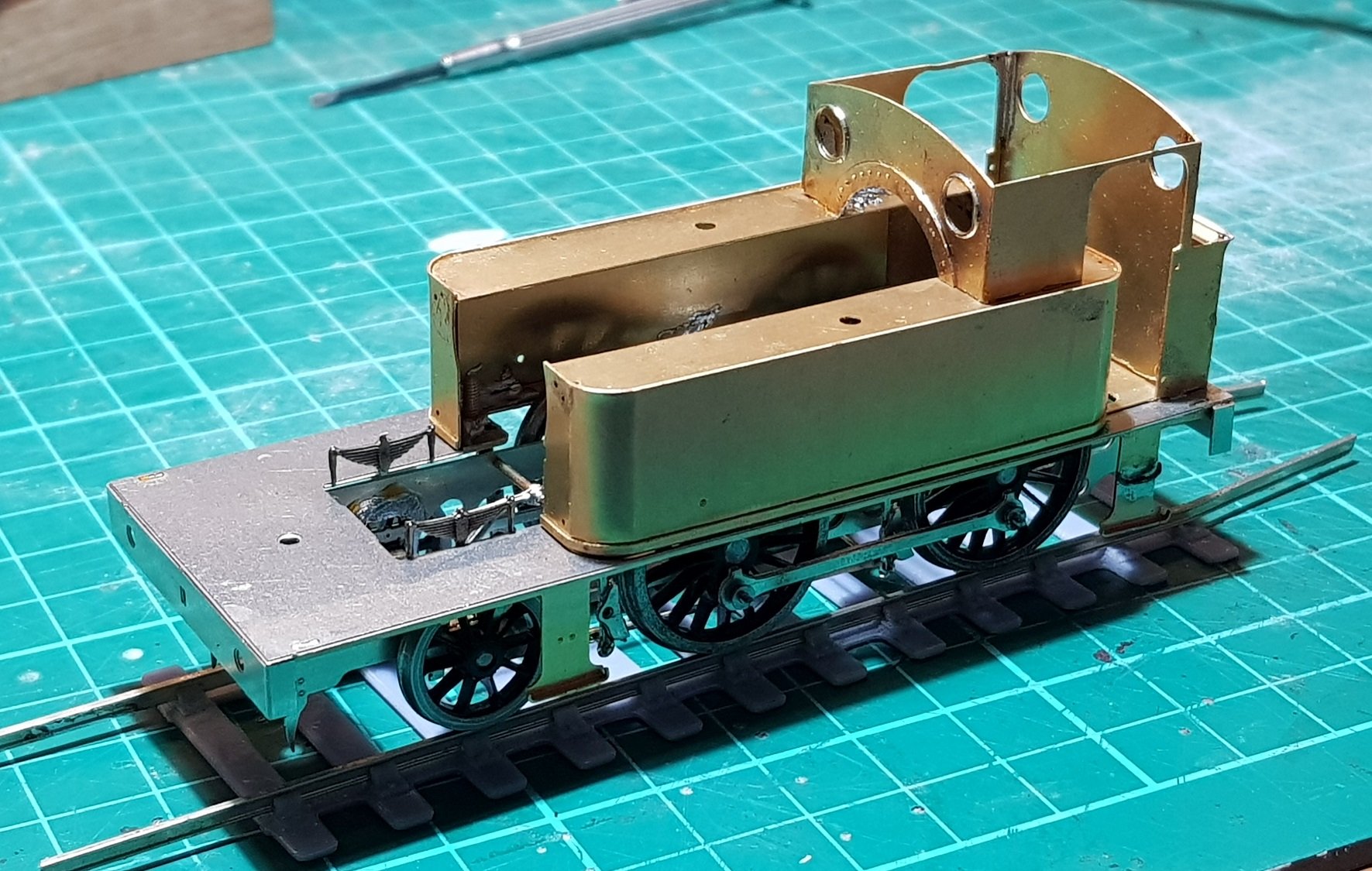
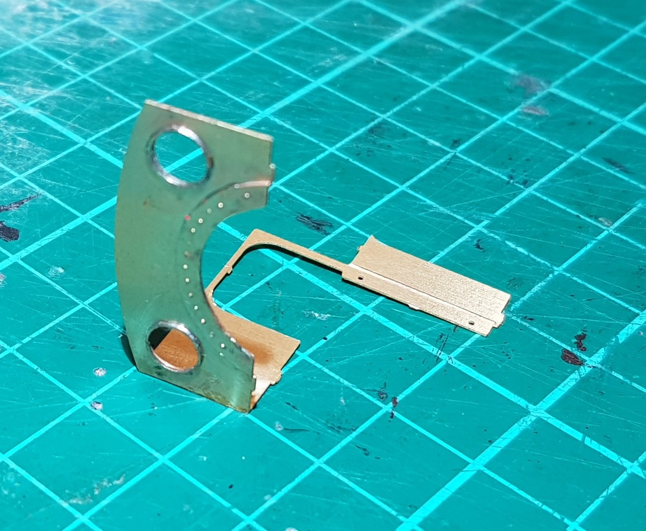
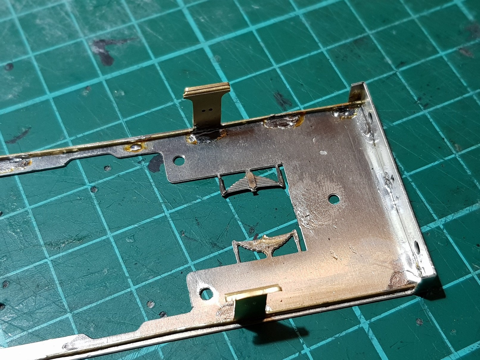
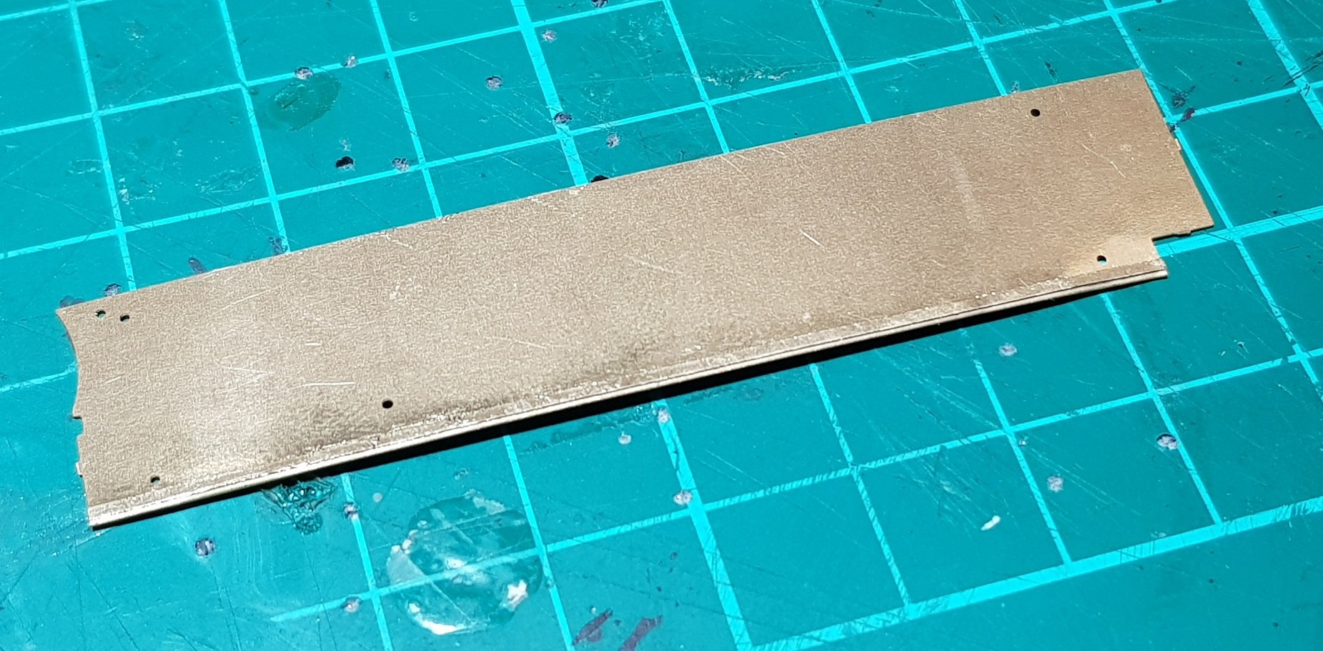
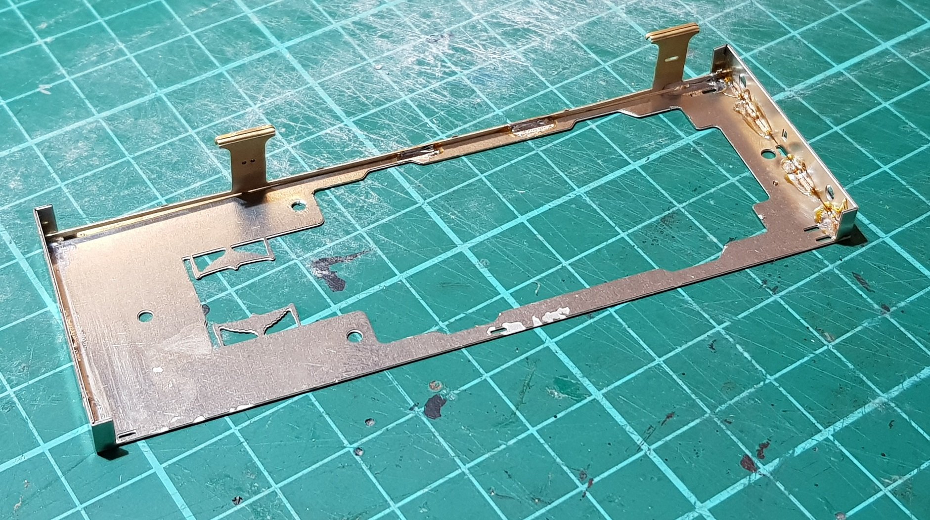
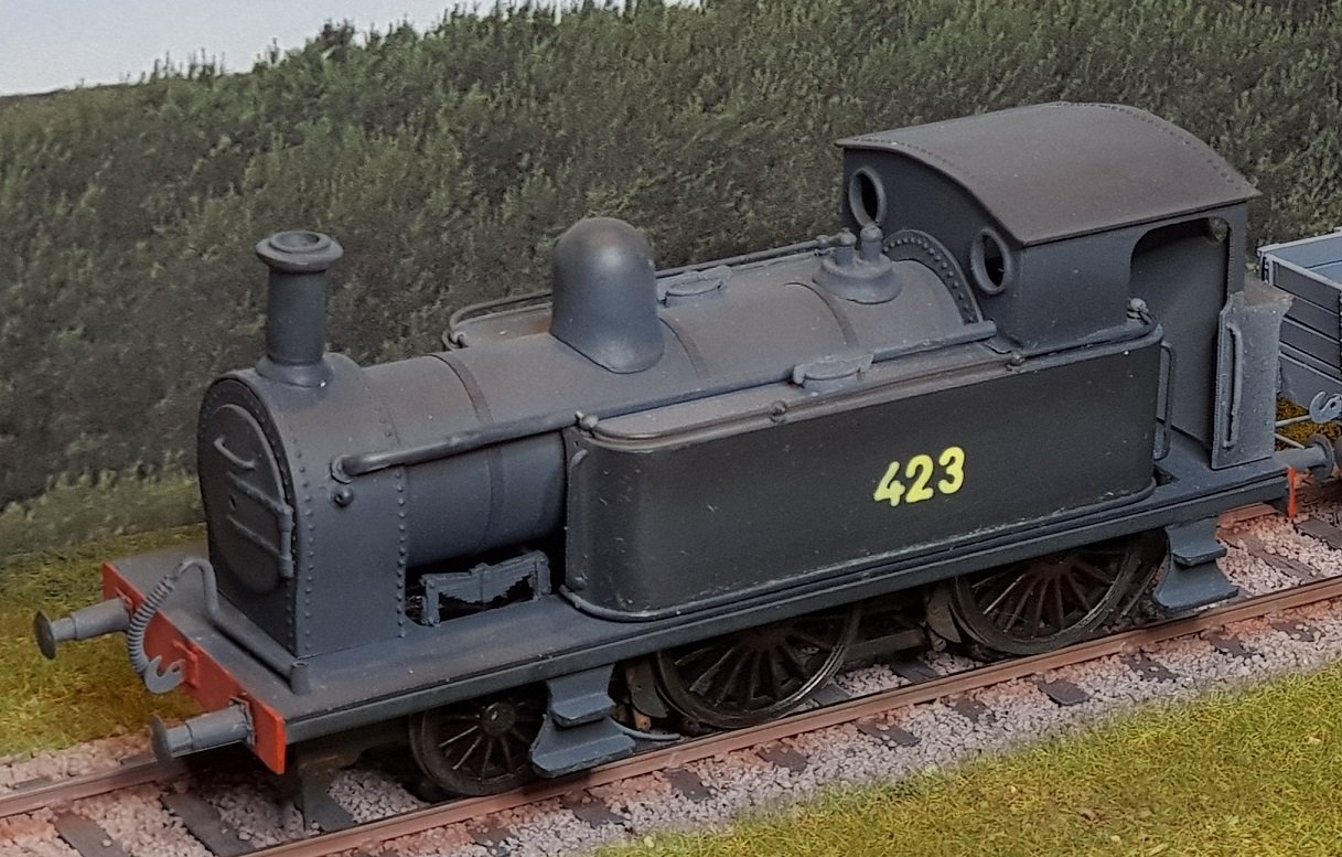
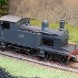
Moving on with the build. Footplate up first. Buffer beams are bent to shape and soldered to the ends. Valances with integrated steps to follow & are soldered into slots provided in the footplate. Additional middle step proved somewhat difficult to solder in place due to its small size - better to fix this in place while the valance is still in the fret. For this model the valances were included in the 0.3mm Brass, and proved to be a little light - I moved these to the 0.45 Nickle Silver sheet for the 428 model, so should be a little more robust. Next element is to double up on the front axle springs. Two layers of springs were sweated together prior to bending up into position. Side tanks are up next. Based on experience from building the first version of this loco, I developed a tank base former to help shaping of the tanks, but also to provide a fixing point to the footplate. Fixing nuts were soldered while the former was on the fret and using the footplate underneath to ensure all lined up. The 423 Class has a band at the bottom which was created by folding back a preformed band from inside to outside. Tank sides were formed using 8mm bar& tweaked to fit the tank top and former. A recess was formed in the side close to the top to set the position just below the top ensuring a consistent step - this should avoid the need to add beading to the tank tops. Tanks thus formed it was on to cab formation. Spectacle frames were added to front and rear cab sheets, while the rivet detail was sweated on to the cab front. Grooves provided on the cab sides help to locate cab front & rears. Bunker rear has a half etched band at the top to allow the curve to be introduced. This should be soldered into place before the cab back is installed due to the lack of space. This cab assembly can then be located on the tanks using the slots provided, while the rear of the cab / bunker is soldered to the tank former. This provides a rigid structure which can then be bolted to the footplate. Band at the base of the tanks mentioned earlier is a little more visible in these shots. Starting to come together nicely. Up next - boiler & smokebox.

-
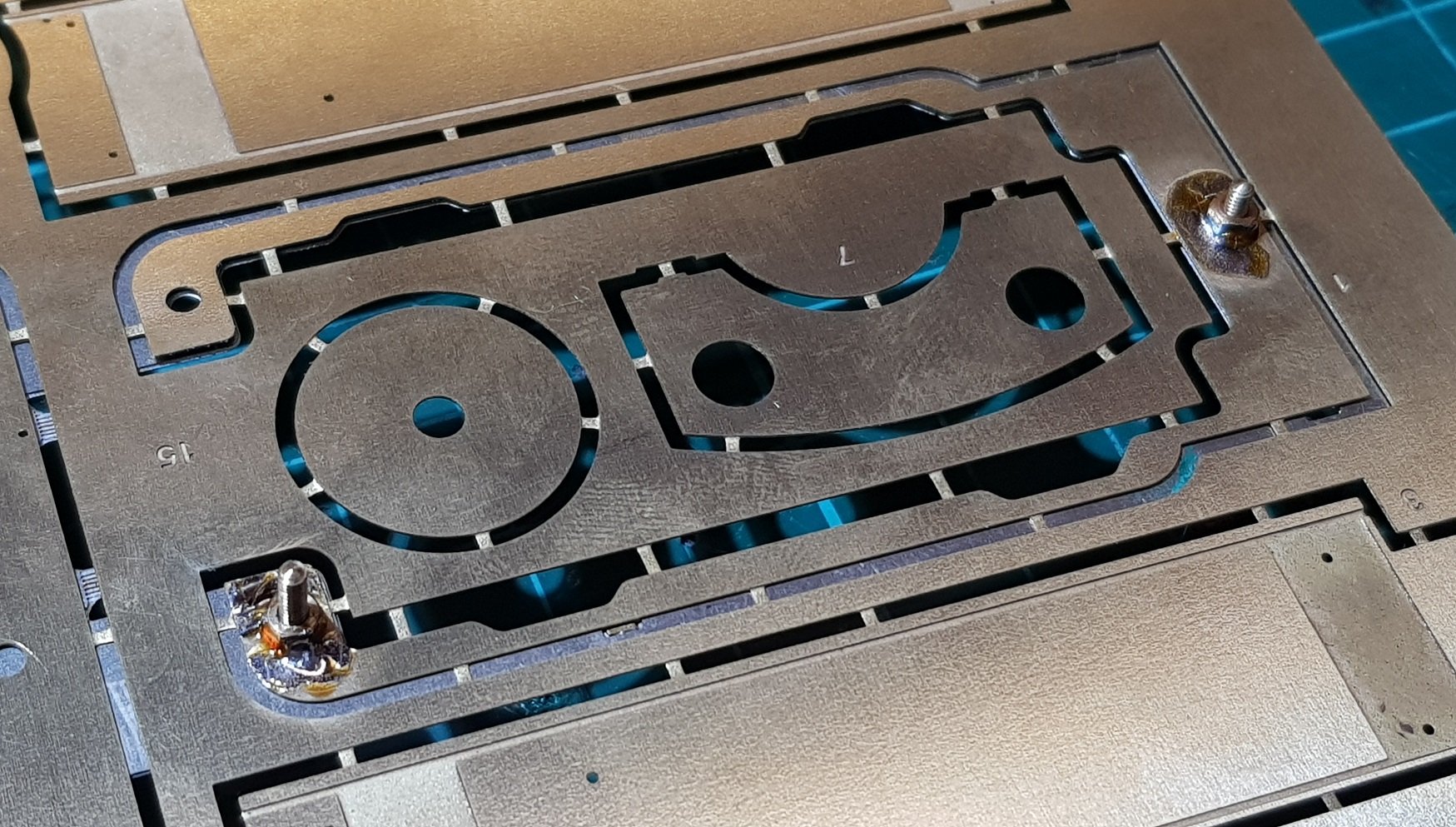
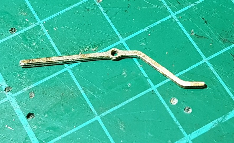
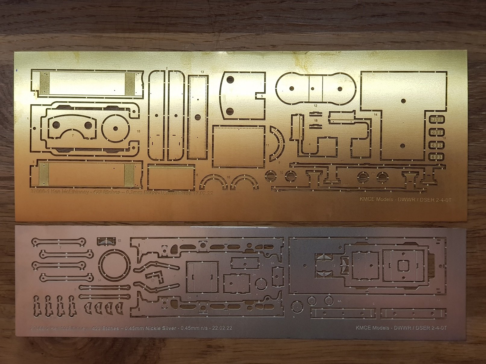
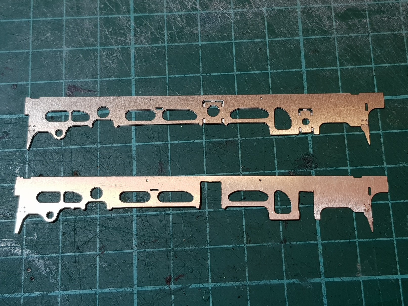
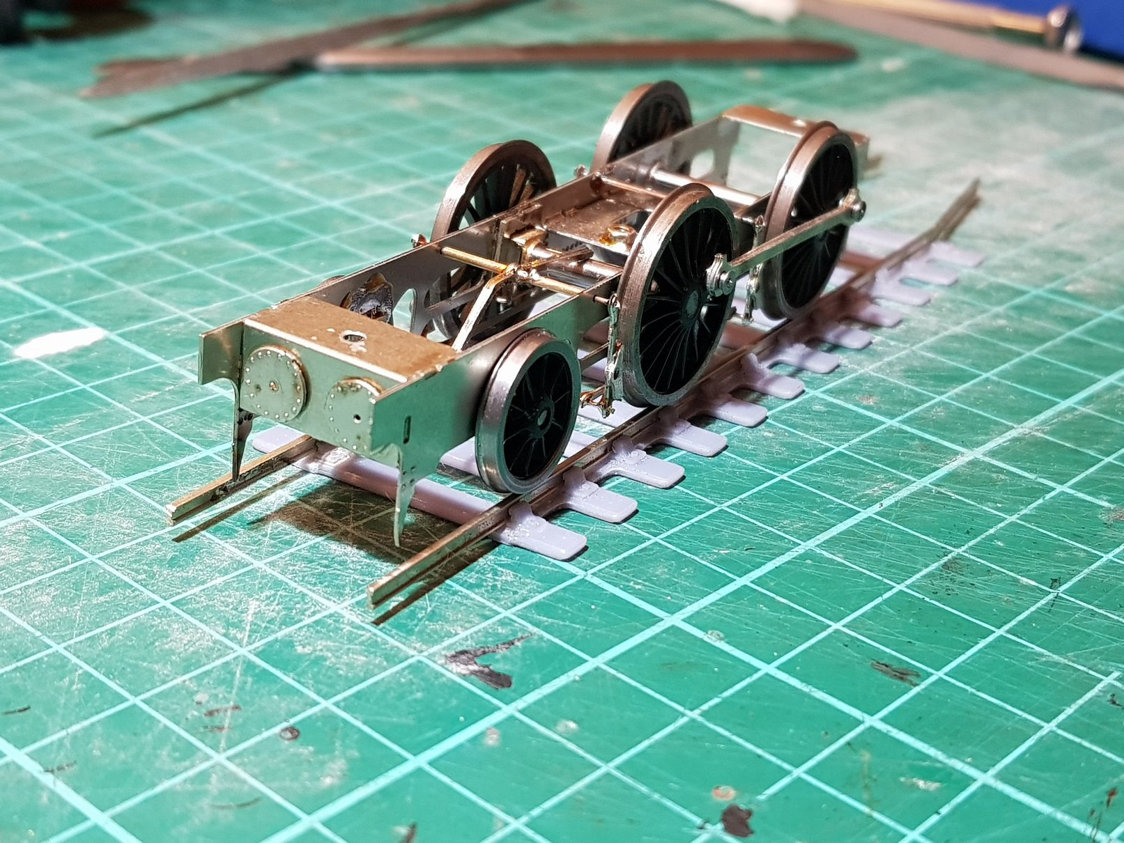
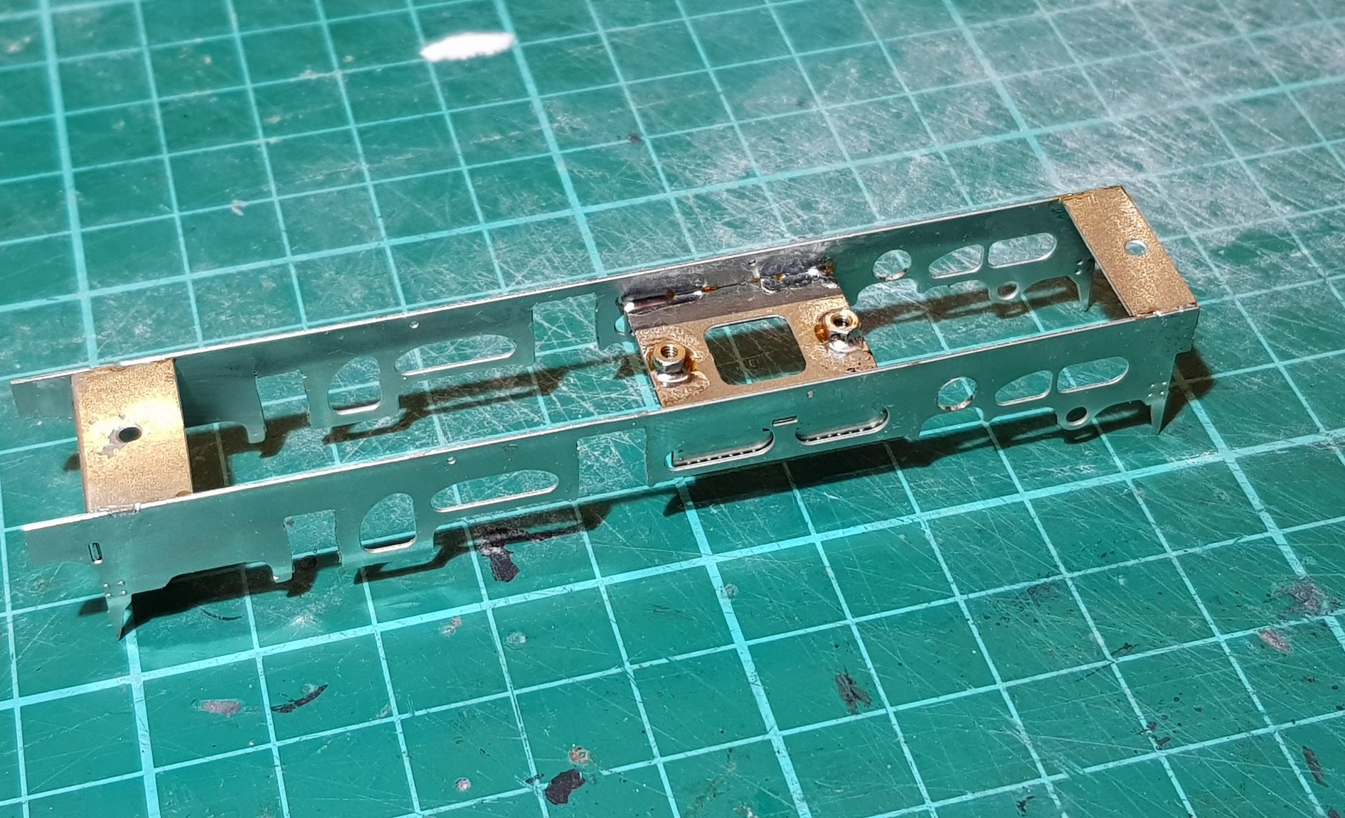
So..... Part of what has been going on in the background was the development of Etches for some locomotives - DWWR / DSER, as to be exptected, in this case the 423 Class 2-4-0T (being the most numerous on the DSER line) and its extended version the 428 Class 2-4-2T. Etches arrived back from the excellent people at PPD Scotland, and I decided to build the 423 Class first to ensure the etches are correct. The intention here is to develop kits of both locomotives for both OO and 21mm Gauges. The etches are 0.45 Nickle Silver for the chassis work and 0.3mm Brass for the bodywork. I intent to include 3D printed elements for chimney, smokebox front, dome, safety valves, tank fillers and buffers - all of which have been developed and printed ready for the model. Nothing for it but to get stuck in. Frames were removed from the fret & in this case material removed to allow the 21mm compensated version to be built. The material to be cut out for the hornblocks is substantial enough to allow for a strong fixed chassis version. Frame spacers next and are include three: front with angled plate to take faux cylinder heads, centre spacer with fold down sides to simulate firebox and plain rear. The centre space for the 21mm version has been designed to take the RC switch / charging point alluded to in the posts above. Matching spacers (less the RC Switch cutout) are provided to build the chassis to OO gauge. The 21mm compensated version needs hornblocks and compensation beam. Hornblocks are those from High Level Kits, whilst the compensation beam is included in the etch and is doubled up, sweating the two parts together. Installing hornblocks for compensation between front bogie and leading driver is more difficult that just using the normal axle setup box for coupled axles - the front axle being centered lower than the main drivers. I created a jig which centres on the rear fixed axle and lines up using the brake hangar holes in the chassis. This allowed setting for both hornblocks at the correct height & true. All of this bringing us to a nice rolling chassis. Set up at the moment is on a spare set of EM drivers - correct P4 wheels will be added once all the work & painting is complete. So far, so good. Compensation beam needed only a very minor tweak to get the chassis sitting level. The only minor issue at this stage is the hole in the brake shoe is slightly oversized, so lining up with the hangar was by eye rather that using 0.5mm rod as originally intended. On to the body next.....
- 379 replies
-
- 10
-

-

-
Thanks for the comments guys - much appreciated. To respond to a few comments: The receiver has the capacity to handle a stall up to 1.3A @13V so should be capable of running your motors From recollection the recommendation is for loads up to a maximum of 1A for this receiver. With the additional space I would go for bigger batteries which would give longer running times (longer charging though) which should get you through a days operation. Interesting comment and is probably something I should keep an eye on. I have been dealing with Andy from http://www.micronradiocontrol.co.uk/ who has proved very helpful with advice and providing a complete solution except batteries - he cannot ship LiPo batteries, however he did provide me with contacts to his suppliers in China. The receivers and parts for the transmitter are supplied to him by http://www.deltang.co.uk/. Deltang have been upgrading their receivers, but so far have all been compatible - so no problems so far. I really like this idea. At present not possible with the charge controller I'm using; it's not possible to charge when the power is switched on to the loco. That said, I wonder could an intelligent charge controller be switched using one of the spare switching controls on the receiver - i.e. select the loco with the controller & push a button to disconnect the charging & allow the loco to operate. For me the best place for this charging facility would be in the fiddle yard where there are simple lengths of track, easily cleaned. Locos charged & ready for use on the layout, meaning no wiring needed on the main lines. Regards, Ken
-
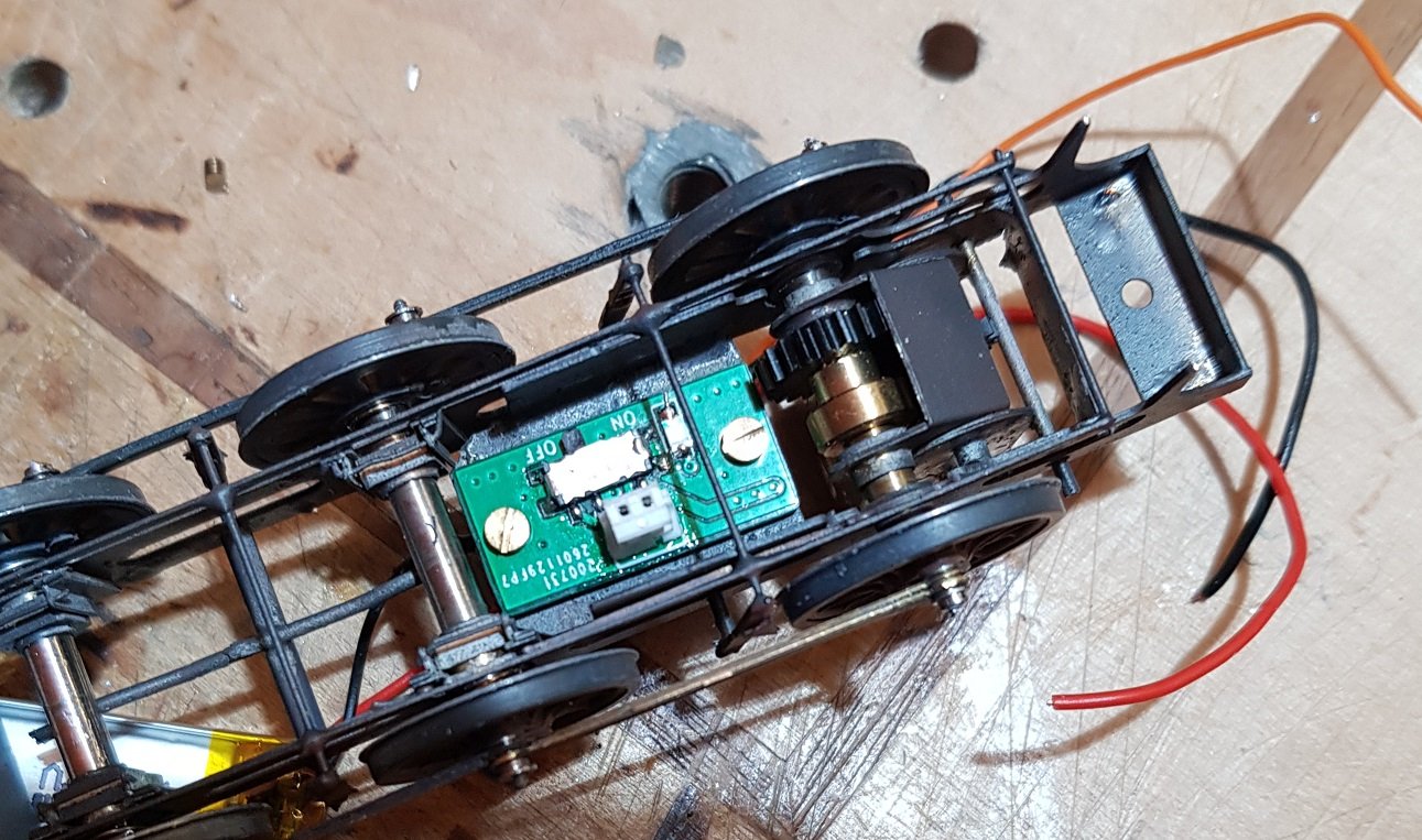
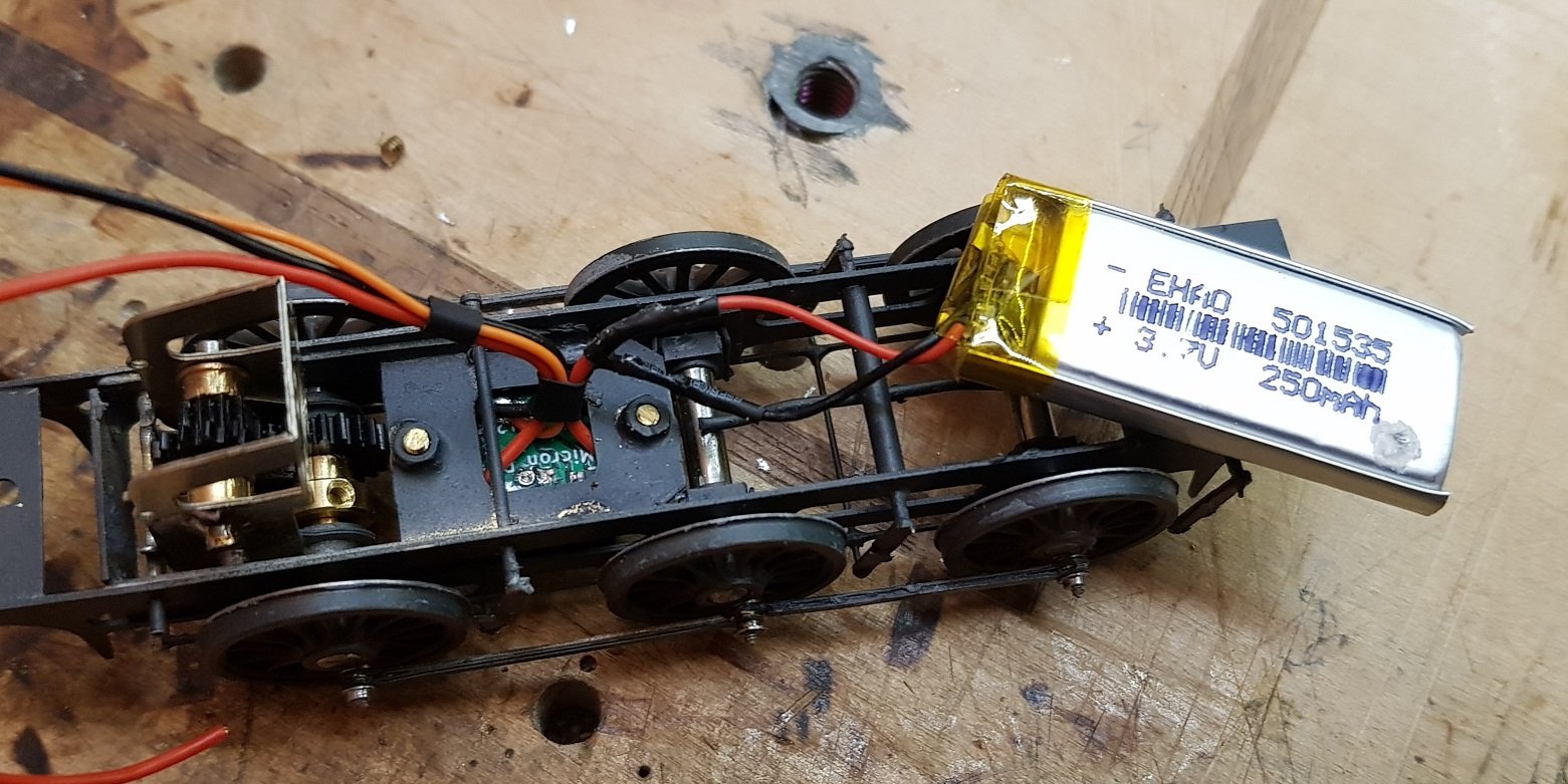
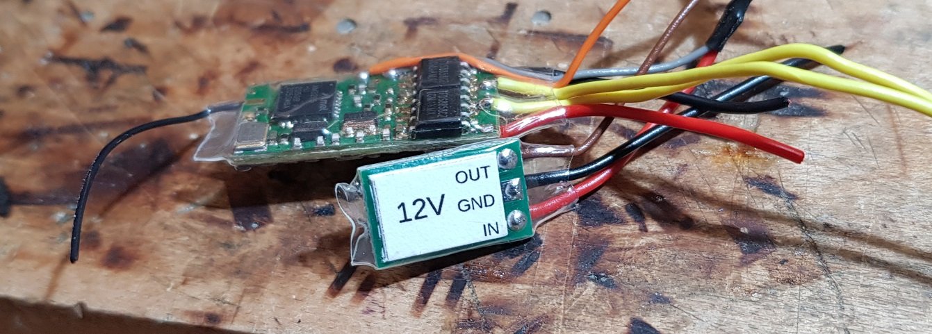
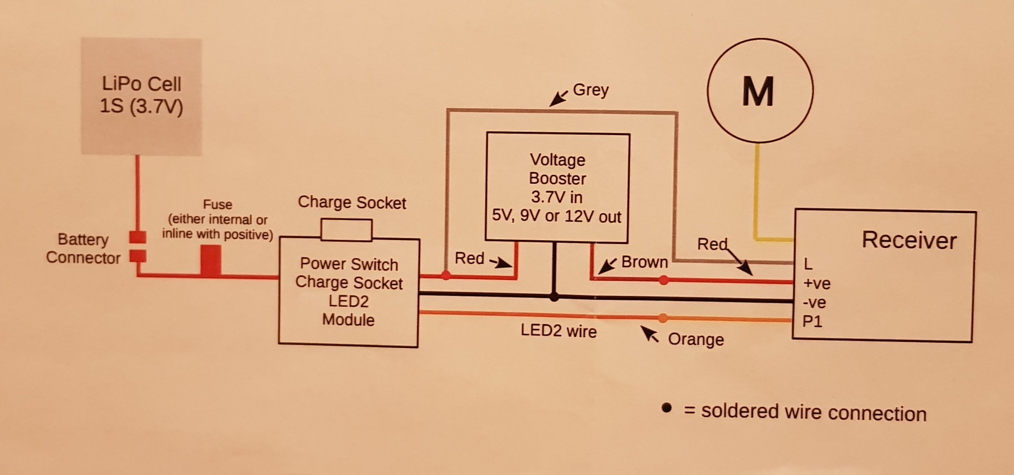
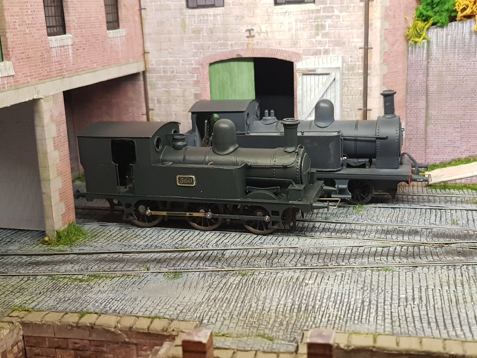
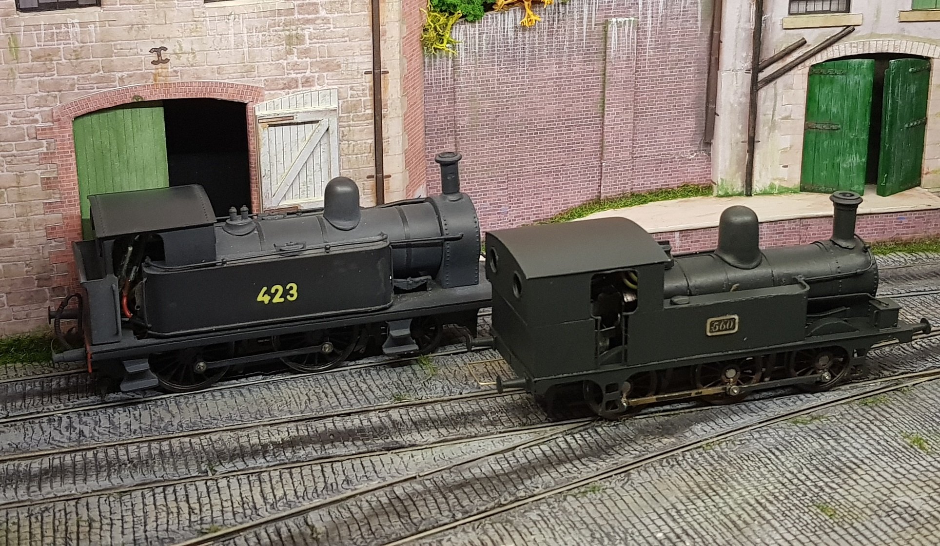
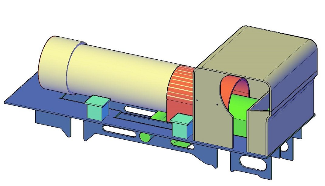
A while since I posted here, but quite a bit has been going on in the background. At one of the Bray shows I purchased a TMD J26 kit from a very kind gentleman who came over to discuss kits etc. This needed a new chassis as the kit version is too light. Chassis was constructed with hornblocks for centre and front axle to allow compensation. Kit allowed for articulated con rods, and are built up in two layers. What was nice is the kit had a number of number plates with it, and I elected to build as 560 with the extended cab enclosing the bunker as used by the Waterford & Tramore Railway. Nearly complete and spent the day completing the electrics & fettling the running to get some relatively smooth running. Still some work to do, but coming along nicely. Shown along side 423 Class. Really need to touch up the connecting rods - they suffered from repeated on & off handling while fettling the movement. As part of this build, I included the RC electrics I have been converting my locos to over the last while. I have not had a chance to post as I have been spending time on developing the methodology of installation. There is quite a bit of wiring to be done, and this can be hard to hide in a loco, not to mention space for all the various components. For 12V locos the normal solution is to use switch / charging connection, single cell LiPo (Lithium Polymer) battery, voltage regulator, receiver / controller, and connection to motor. Finding space for equipment in 4mm can be challenging and the two most difficult are the battery & switch / charger. The switch charger measures c. 20mm x 10mm and must be screwed in a position to allow access to the charging connection so on smaller tank locos generally means underneath between axles. It's not ideal as it means the loco must be picked up to switch on and off (and charge) for each operating session. For larger tanks and tender locos, this switch can be located in the bunker and covered with a false coal load. The battery (in this case a 250mAh) fits in the boiler barrel and is connected to the switch . This battery measures 35mm long x 15mm wide & 5mm deep. This battery is good for 30 mins or more of constant operation with c. 1 hour charge time. This may seem not a lot of time, but if operating more than one loco on a layout is more than enough. From the battery switch a voltage regulator is needed as the battery voltage is only 3.7V. The down side of using this regulation is that the receiver is not able to establish the condition of the battery - over discharge of a LiPo will render the battery useless, so an additional wire is needed between the transmitter and battery. The receiver is shown behind the regulator. The receiver is quite intelligent and has a number of channels which allows inertia motor control, lights, sound, etc, so whilst not as expansive in operation as DCC, does provide considerable control. There is quite a bit of wiring with these modules, but have done a few now, it does not take much time. It can however prove challenging to hide all the cabling within the loco; I will definitely have to add some crew to hide this. The controller is quite basic and rather old looking, but is capable of controlling 12 locos at one time - this does not mean you are limited to only 12 locos - it is a function of which locos you switch on at the time. Each loco is addressed 1 -12, however the only time you will have a conflict if you try to run two locos with the same address number. This may seem a lot of work, but not having to wire track or worry about lack of pick up, or dirty track is rather nice. Once the loco operates, track condition is no longer a worry - you just need to remember to charge them up before a show. To date I have converted 5 locos & two railcars. The one loco proving very difficult to convert is the 495 Class due to the lack of space - this will most likely be a 6V solution as the receiver is smaller, however battery capacity will be very limited thus reducing operating time - the Drewry petrol railcar operates this 6V solution with a 50mAH battery and is quite limited in operation. All in all, quite a learning experience, but well worth doing. Cost wise from Micron Radio Control: Switch / Charging point - £ 6.00 Voltage Regulator - £5.50 Receiver - £29.00 Transmitter (one off) - £65.00 Battery (ex China) - € 5.00 So from a cost perspective, not excessive for individual loco control. Anyway all for now, Ken
- 379 replies
-
- 14
-
-
-

-
Was Granny Bracken available for comment?
-
Many thanks for that information Seagoebox. I was in the IRRS last night and have agreed to meet in the archives in the coming weeks, so that information will be very helpful in directing the search. Cheers, Ken
-
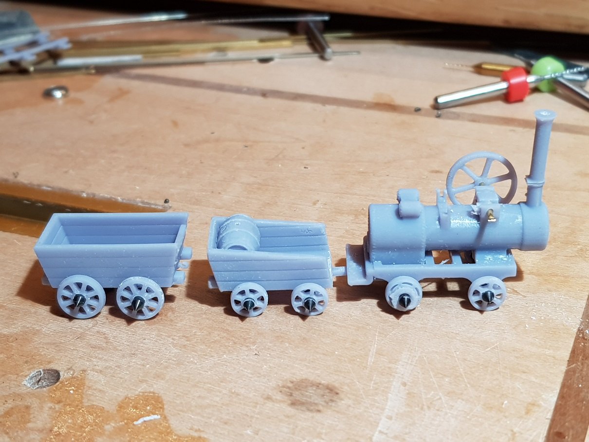
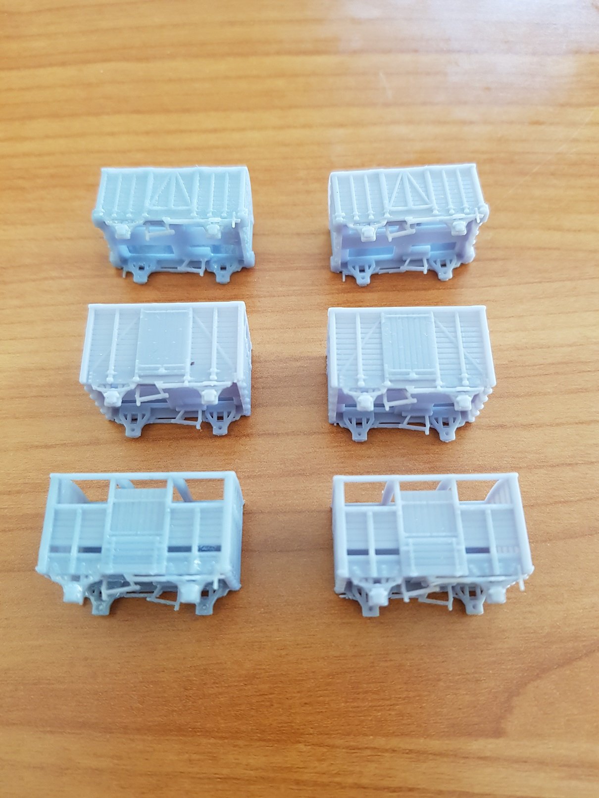
Eoin, Many thanks for that - I had neglected to look to Shepherd & Beesley and was using an article published by the Mineral heritage Trust of Ireland (https://mhti.org/uploads/2/3/6/6/23664026/the_avoca_mineral_tramway_a_further_look_into_an_early_co._wicklow_mineral_tramway._waldron_a_et_al__2004_.pdf ) which also noted that the section between Ballygahan and Arklow was 3'6". The run of the mineral railway to Avoca was sold to DWWR who used the trackbed for their own line with a new mineral line was installed away from the river. A transfer siding was provided in Avoca, to which the tunnel above connected, the tramline being elevated above the rail line to allow easier transfer. What has raised this query is a photo I discovered on the NLI which shows the ore wagons on track to the South of the station and bridge (https://catalogue.nli.ie/Record/vtls000338942 ). Any photo I have seen shows a twin 5' 3" line under this bridge, so I am a little unsure of how these ore wagons get to the South side of the bridge if they are 3'6" gauge, hence the query on the tramway gauge. What is also interesting in the NLI photo is engine shed and turntable - the turntable looks more like a glorified wagon turntable & it is noted that DWWR had responsibility for maintaining and housing the locomotives, so perhaps this is the tram loco shed? Sadly the OSI historical maps do not show any tramlines . I am in the process of building a model of the tram loco and wagons based on the 3'6" gauge, and from dimensions the wagons could have carried 2 tons of ore as noted by Shepherd & Beesley so these elements tally. Assembled temporarily with pinpoint axles - these will need to be trimmed before fixing. These are really small, the ore wagon being 22mm long - for context that drill in the background with the red collar has a 3mm shank. The intent here is to develop a model of Avoca station with the tramline in the background with the tipping wagons on the transfer siding in the background. I'll post more in the Layout section once I get an opportunity to make some progress. Ken
-
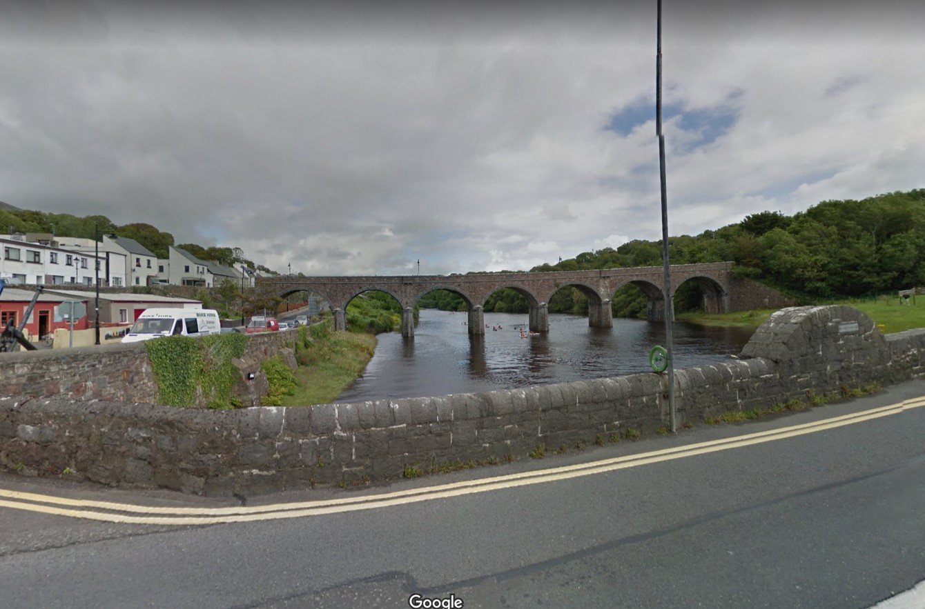
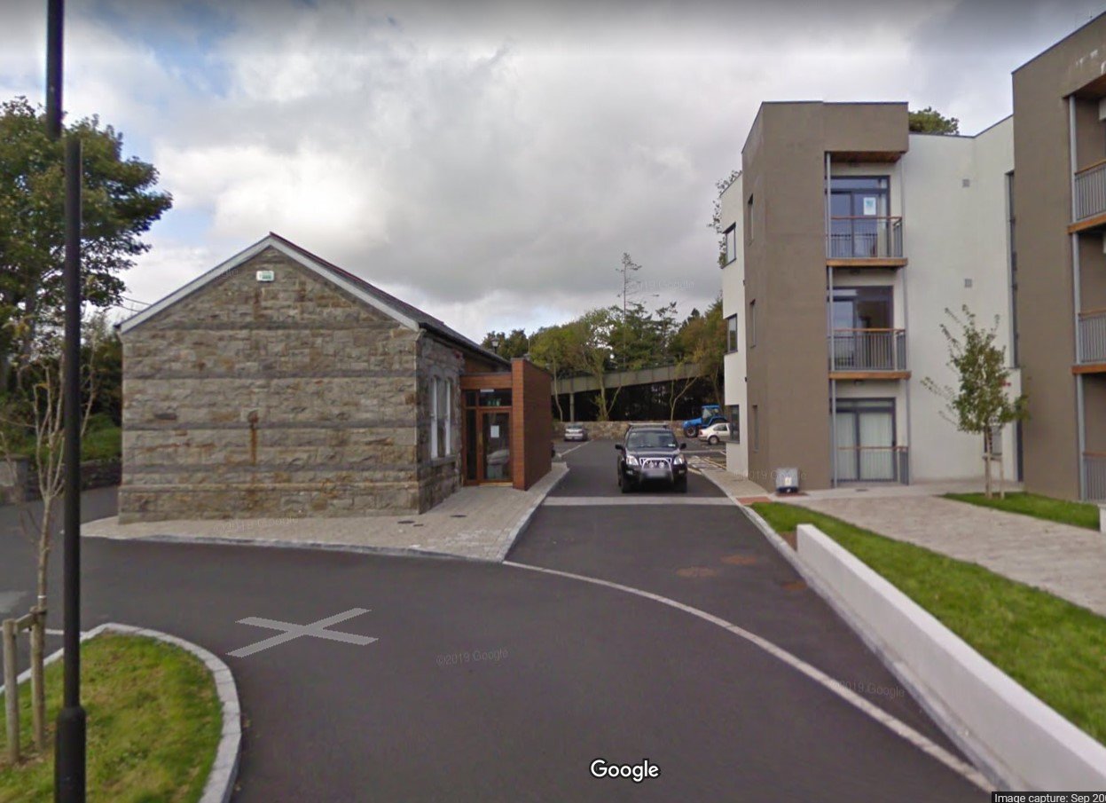
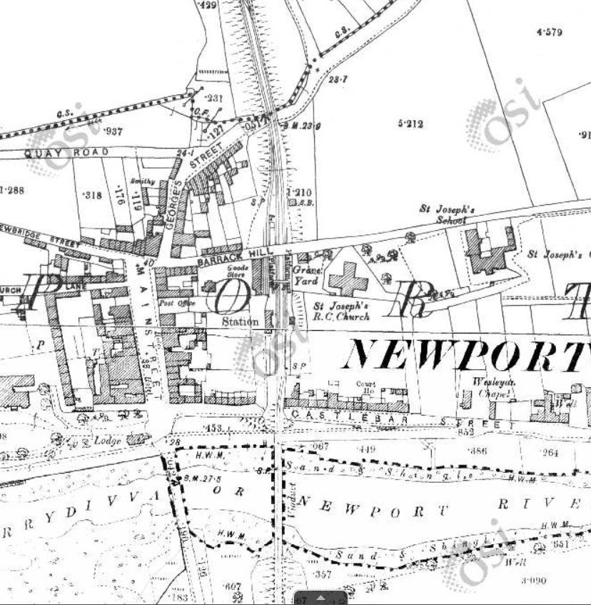
 As an option for the MGWR flavour, would you consider Newport. Visually very impressive with the multi arch bridge over the river, the incoming line emerging from a tunnel crossing the bridge and entering the station. The road bridge on the North end of the station provides an excellent scene break with the opportunity to use a sector plate or traverser / fiddle yard depending on operating preferences. Looking North to the road bridge along the original trackbed. Photos courtesy of Google Maps. A view of the original station from OSI historical maps Although not in my area of interest, it was a station that I thought would provide some excellent visual and operational potential and thus a good layout. Just a thought Ken
-
Many thanks for the reply WaYSidE. Any information would be appreciated. Ken
-
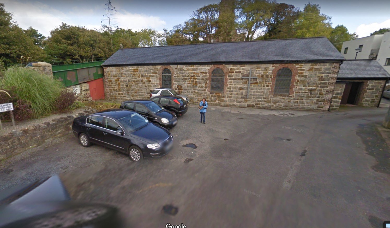
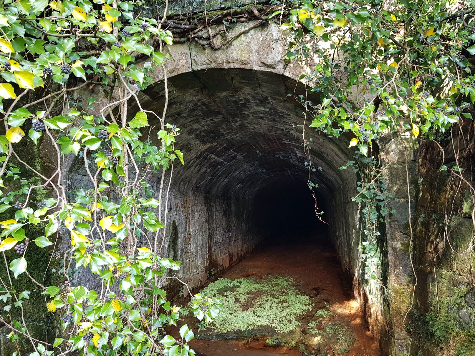
Just doing some research on the ore transfer between the mines and the DWWR line at Avoca. A tramline with associated locomotive and wagons ran from the mines down to a transfer siding in Avoca station. From my research, this ran from c. 1864 to 1900, and I have managed to source some photos through the NLI online archive (can't show the photos here now due to negotiations with NLI re copyright) but I have managed to source some photos of the 1872 3 plank wagon and tipping wagon I am currently making models of. What would be nice is to develop a model with the tramline and ore loading in Avoca. I have some details on the tram ore wagons & a sketchy outline of what the tram loco may have been. Where I am struggling is the gauge of the tramline. I have some information which notes that 7' sleepers were used. A tunnel under the road leading into Avoca carried the tramline which is still there, and there does appear to be some sleepers left, albeit seriously covered on debris etc. Photo taken 03/03/2022. Tunnel & some remnants of sleepers are still there a minimum of 120 years since it was last used which was impressive to view. Would be nice to bring this back to awareness, so if anyone has info on track gauge of the tramway, it would be much appreciated. Ken
-
PRE-GROUPING AND GSR COACHES IN THE CIE ERA FOR MODELLERS
KMCE replied to jhb171achill's topic in General Chat
Not sure - I don't think I could stitch that small..... -
Coming along very nicely. That will make for quite an imposing entrance from "stage left" Have to confess, when I saw the first image without reading the narrative, I thought you had outdone yourself !!
-
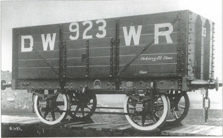
DWWR I have is 8' 6" wheel base and 14' over headstocks, so perhaps something similar?
-
Nice image, and really shows off the split spoke wheels used by many of the companies for their wagon stock. With a bit of tweaking, a version of this in 3D should be possible. @jhb171achill, what wheel base is that wagon do you know? Ken
-
That would be me. The model as arrived was very rough & the dilemma was whether to sand like hell, and lose the detail, or heavy primer & hope for the best - I went for the latter, and have a passable model. With respect to N-Gauge printing, I have printed out quite a few for customers with good quality results using resin printing. These were printed with basic settings of 50micron layers. I may try again with finer settings, perhaps 35microns to see would it improve fidelity. More info in the Manufacturers Section
-
Some good comments here. One thing also to try is to move the camera back and zoom in - it helps with the bending or distorting you mentioned - it also helps with that front and rear focusing you mentioned. I does take a steady hand, or a tripod as others have mentioned. I learned this from taking photos of furniture in the past - way back & zoom in!! Ken
-
You gotta love the correct gauge - just sayin....... Ken
-
Same one I use....
-
Having tried both methods of production, the main issue is weight. A 3D printed loco body may only be c. 30 -40g while its brass counterpart may be in excess of 150g. I find that locos need to be over 300g to have sufficient traction to move a rake of wagons. With some locos, finding space for weight can be an issue, and finding space for an additional 100g can be difficult. Also the brass can provide finer detail with superior strength, and it doesn't shrink!! Ken
-
If you were to cut away half of the brakes, you would have a very good look alike for a 1904 DWWR Hurst Nelson Open wagon?
-
True - it's only a small one after all.......
-
A little late to this party, but one worth joining!! One of the goods engines ordered in 1863 & delivered in 1864. Lasted in operation until 1924 before being scrapped in 1925. It's compatriot No. 21 was re-built as a tank engine in 1905. It's a model I should build, and will get to it in time; too many other projects on the cards at the present to make any meaningful progress. As to the 2-2-2 WT, they seem to have been well covered in the comments above. Quirky locos, but appeared to have provided good service in various guises from 1865 to 1923. It's a loco that I'm planning on building to run with the small side tipping wagons built earlier. Design is proving difficult due to the lack of space for motor, gearbox, battery, etc, so I am developing in 3D first before building in Brass. Model is 96mm over frames with no tanks or other hiding places so an enclosed cab version is the only way to proceed. This will be a model of No. 35 built 1873, withdrawn 1923, so should work well with turn of the century rolling stock. Agreed, they had quite a number of tank locos of different sizes and that particular example became the GSR 423 Class - nice loco & good model. I am proposing to build another of these and may go down the etching process to develop a kit. Fittings can be 3D printed as suggested above. A little bit of fine tuning will be needed to ensure the etch version can be built in OO and 21mm versions. @jhb171achill JB, if you have any more photos of the DWWR / DSER, it would be most appreciated. Those posted by you, and others here are most appreciated. Ken
-
Shouldn't be necessary. The joggle is normally put in the diverging rail which ensures the gauge on the main line by allowing space for the switch rail. When diverging, the joggle maintains the gauge of the switchrail on the other side. It is an area that I have found needs much fettling to get right. Ken
-
Hello Jaz & many thanks for your comments. I agree the paper cobbles were not good which is why I did use DAS clay with a 3D printed roller to replace the cobbles, which I think look much better now. The boat is from Model Slipways (who appear to have closed down) - a 1/72 scale Steam Drifter which I cut down to waterline model as part of dock scene. Regards, Ken
-
No, it's just tedium, and we are all sentenced to it as punishment for our interest in model railways!!