KMCE
-
Posts
540 -
Joined
-
Last visited
-
Days Won
29
Content Type
Profiles
Forums
Events
Gallery
Blogs
Everything posted by KMCE
-
Ernies Massive Irish 1930's to 2005 Photo Archive
KMCE replied to Glenderg's topic in Photos & Videos of the Prototype
Super example of how these locos weathered over time. You could pick any dark colour as a livery & be partially correct! -
All the expensive & rare antique furniture was cut in the same way. Nothing wrong with those skills!
-
Ok - so the Mk2. Fixed a number of problems from the first version. Strapping was beefed up and properly supported so came out much better. Axle width & height was adjusted slightly as the wagon was running too low on the rails and wheels were not running freely. Buffers were beefed up and came out with a much more defined shape. Not sure the Spratt & Winkle coupling system is going to work with these as it may be too big. Thinking of grouping these into a rake with S&W at start & end with 3 link coupling between. The wagons are really short with a dimension of 48mm (12ft), which means a train of them does not take up much space! Need to sort the couplings & get them into paint. Very please how these turned out; Quirky wagon with plenty of character! Ken

- 379 replies
-
- 13
-

-

-
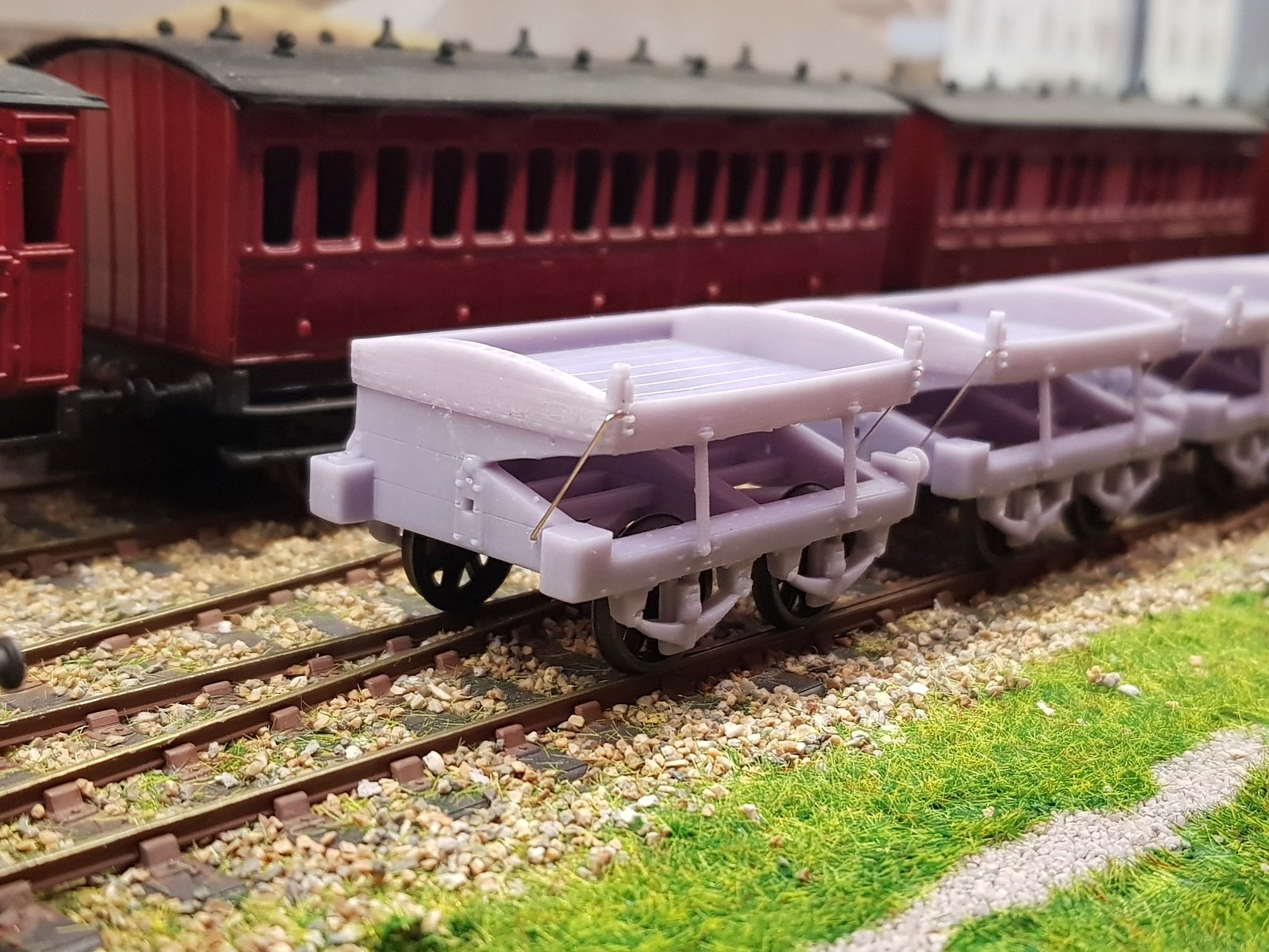
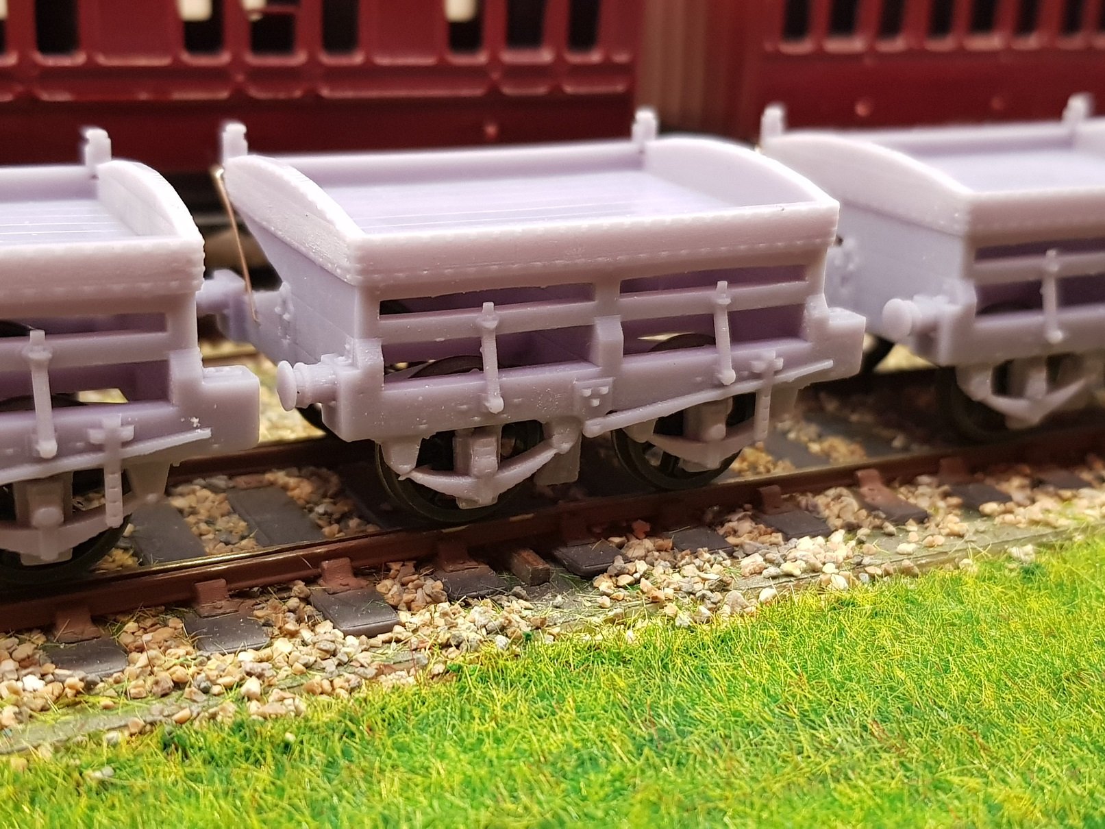
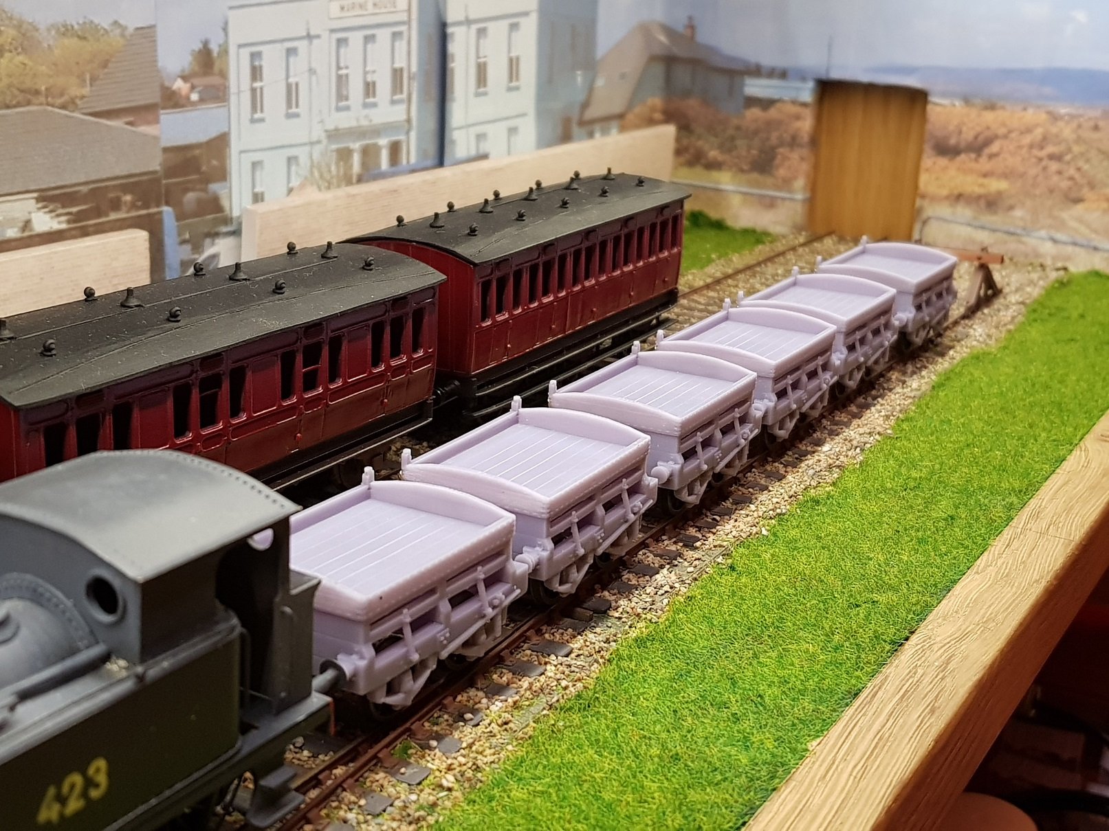
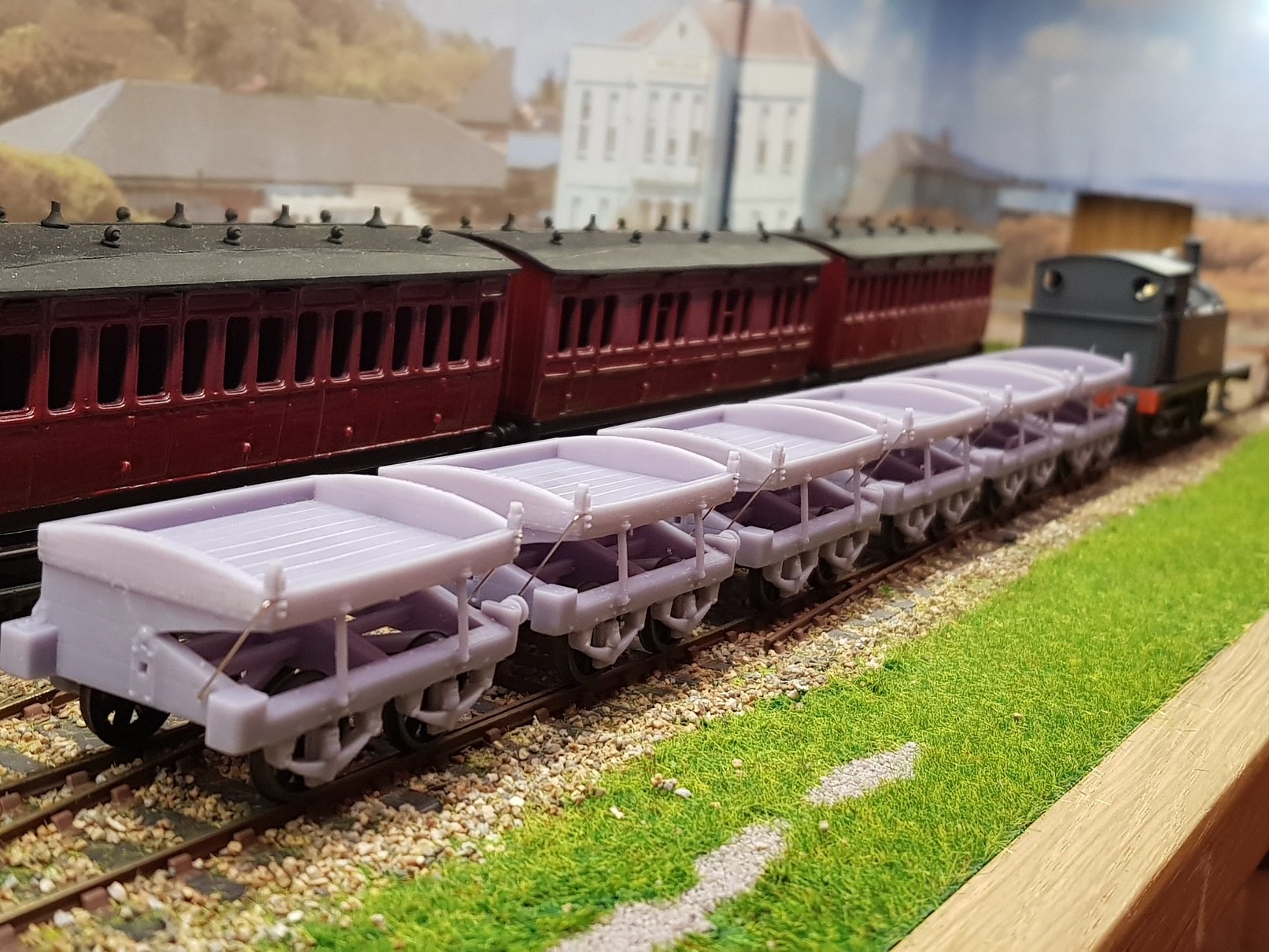
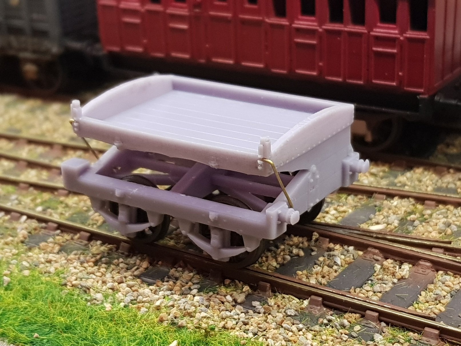
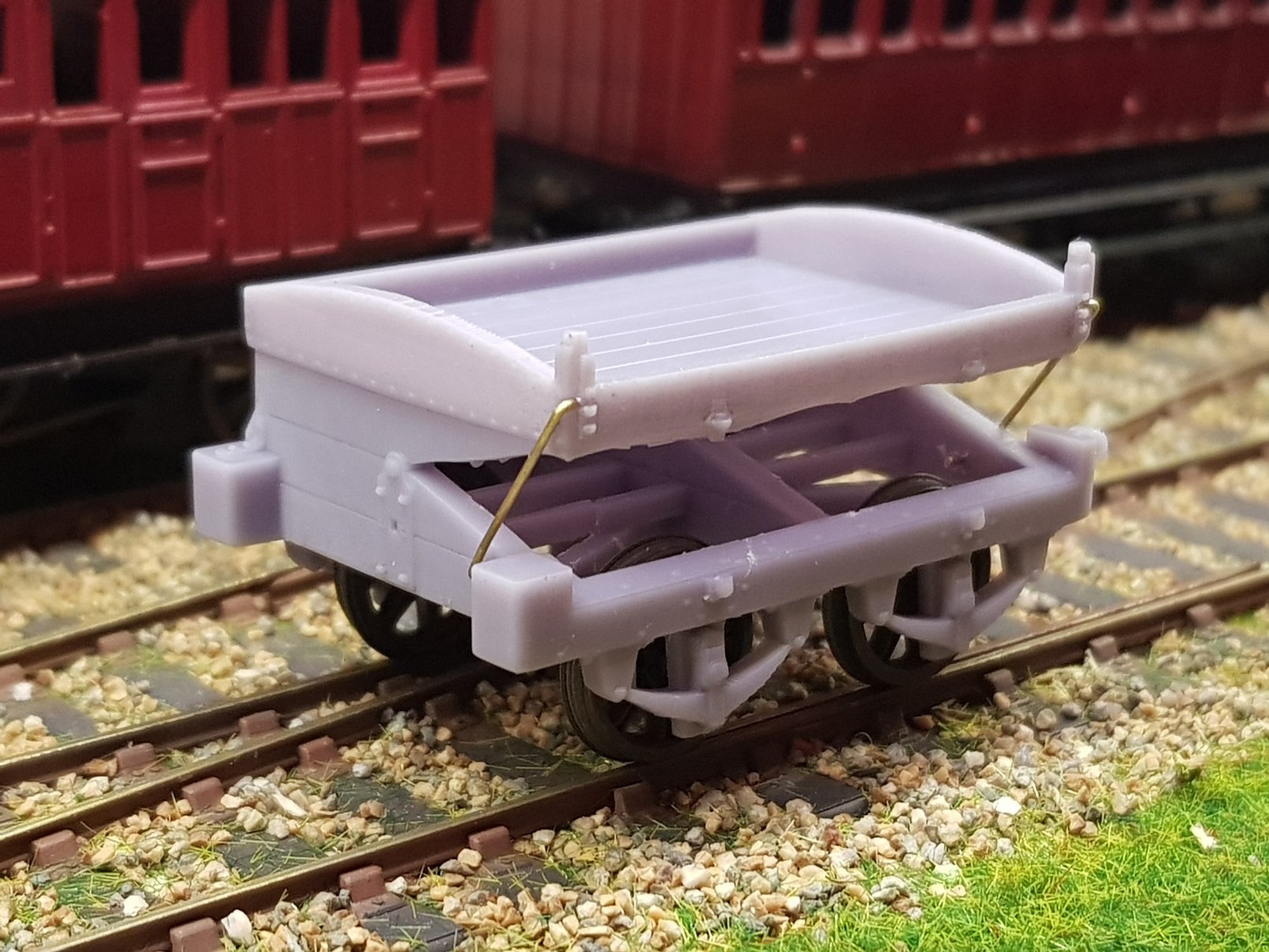
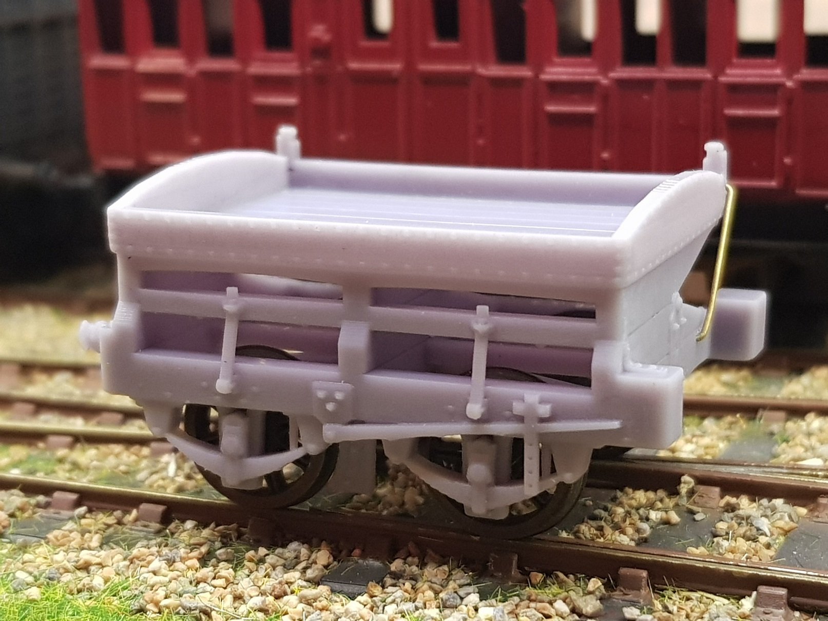
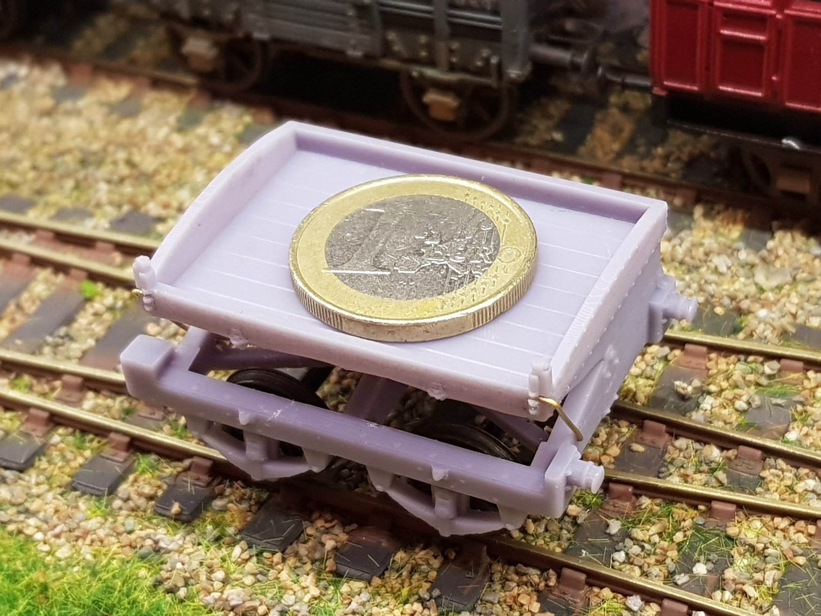
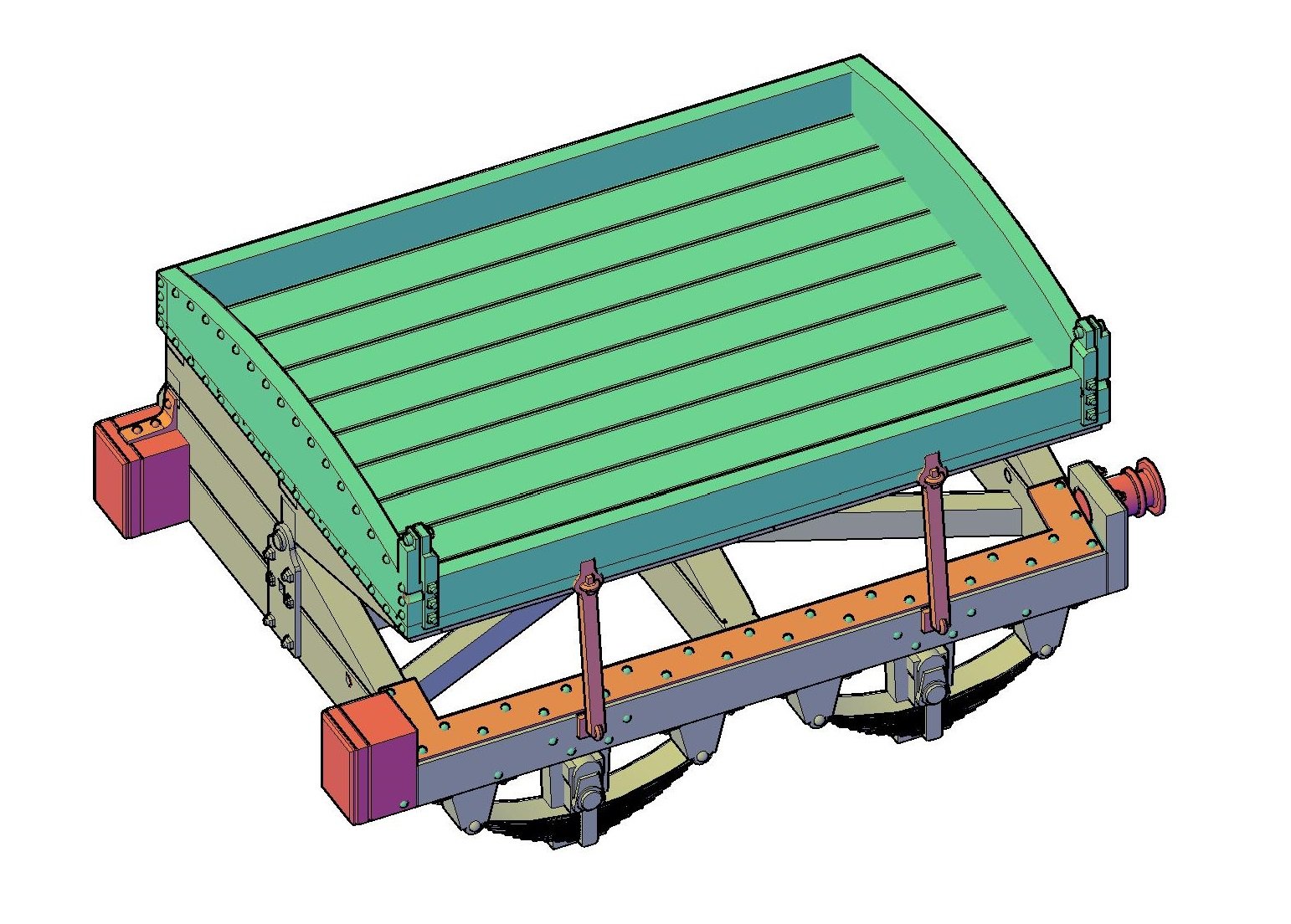
They were indeed. Those wagons were ordered by DWWR from Metropolitan Carriage & Wagon Works (MCW) in 1863 to be delivered the following year. Just preceeding them were the tipping wagons which were very short with a 5' wheel base, and luckily a drawing still exists with the HRMS. These wagons were ordered in early 1860's, most likely from J.Wright & Sons as MCW was only incoporated in 1863, however the drawing with HRMS is labelled by MCW; perhaps a revised drawing post 1863? As version of these wagons was used by the Furness Railway in the UK. These wagons were ordered specifically for the movement of copper ore from the Ovoca (Avoca) mines to Kingstown (Dun Laoghaire) mineral wharf, with an initial 20 delivered in 1862. Usual drawing development from the original HRMS print through to 3D model. A complex model as it has no floor on the chassis, so chassis contsruction is visible (no hiding then!). Intersting arrangement of springs & axleboxes, and given the vintage, these may be grease filled rather oil filled. Model printed well, but strapping on open side proved to be to flimsy and was lost in the clean up process - this will need to be amended in the revised version - I may change these to brass strip in later versions. Underside of tipping element will need some additional suports, as this sagged during the print. Supports in this instance were up through the chassis which proved interesting when removing. This model will need more focus on the placement of suports to get a cleaner and more accurate model. Buffers are designed to scale, however they do look very small, so perhaps a little modelling licence can be applied to improve the look. As can be expected with a 5' wheel base this really is a small wagon, and for comparison a €1 in the mineral bay. It is on the cards and was some time off, however given the addition of the Ballast wagon, early mineral wagon, and this tipping wagon, it makes sense to bring that model design & build forward Let's tackle that a little later - enough to be doing here for now.......... Ken
-
Yes, they would be - the detail scales up quite well, and wall thickness at the larger scale does help to strengthen the overall model. PM me if you are interested in partaking. Ken
-
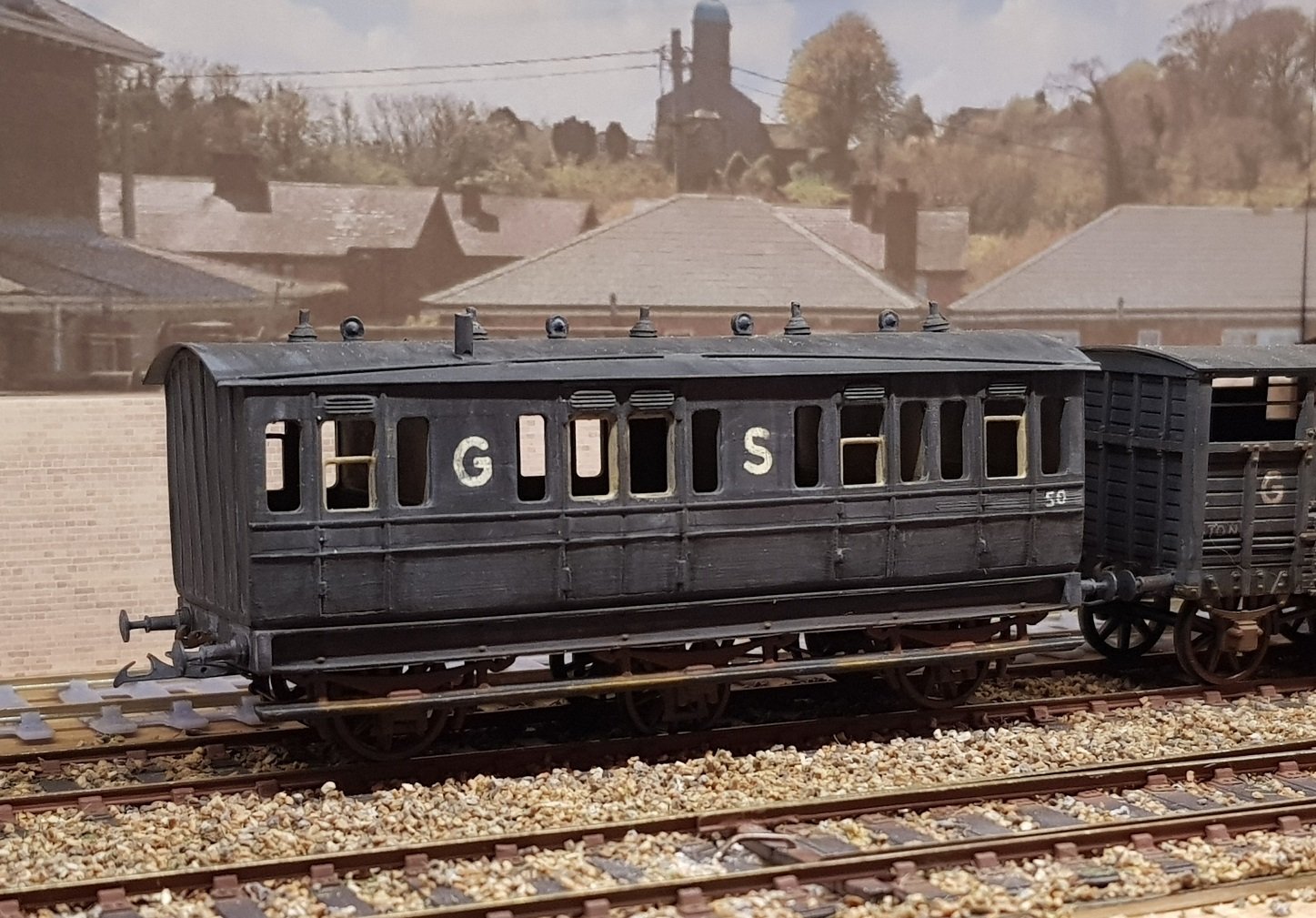
A few tweaks to the CAD model & we get the Mk2 version. I detailed the axleboxes to reflect those used, while reverting to the pre 1907 single (large) brake block arrangement. The seam was put into the inner doors to provide more realistic detail, and some additional supports were provided to stabilse the wagon top to help clarify the detail. A much better model, and perhaps more accurate to the prototype (drawing anyway). And given there was space on the build plate, why not a second to run with! Given these are in their pre 1907 guise, I may finish these as either early DSER or DWWR wagons rather than GS to match the other fleet. With some minor changes to the CAD model, it will be possible to convert these to the later style which can then run in GS trains. I do have a few DSER liveried wagons already & may bring together with these to create their own dedciated trains with suitably painted locos to run with. A repaint of some of the Ashbury & Convertible wagons could add to these trains quite easily. I think I'll leave that to another day....... Ken
- 379 replies
-
- 10
-
-
Most interesting. Some time ago, I scratch built a model of a "Flat Truck for Road Vehicles" based on drawings held by the IIRS. This does have the distinctive uprights, though two instead of the four on wagon 9 above. I will need to check where I got the 144 number from for my wagon, as I would assume it should be similar to 143, but 143 has no uprights! Ken
-
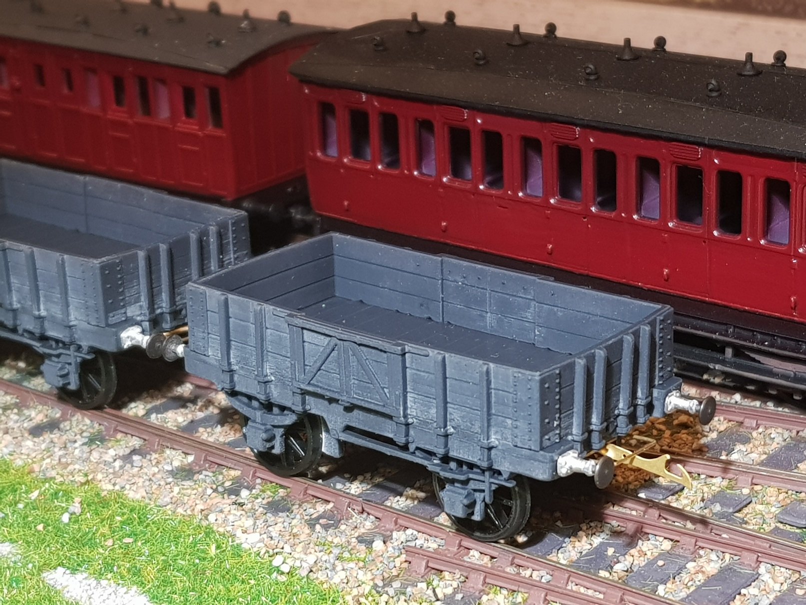
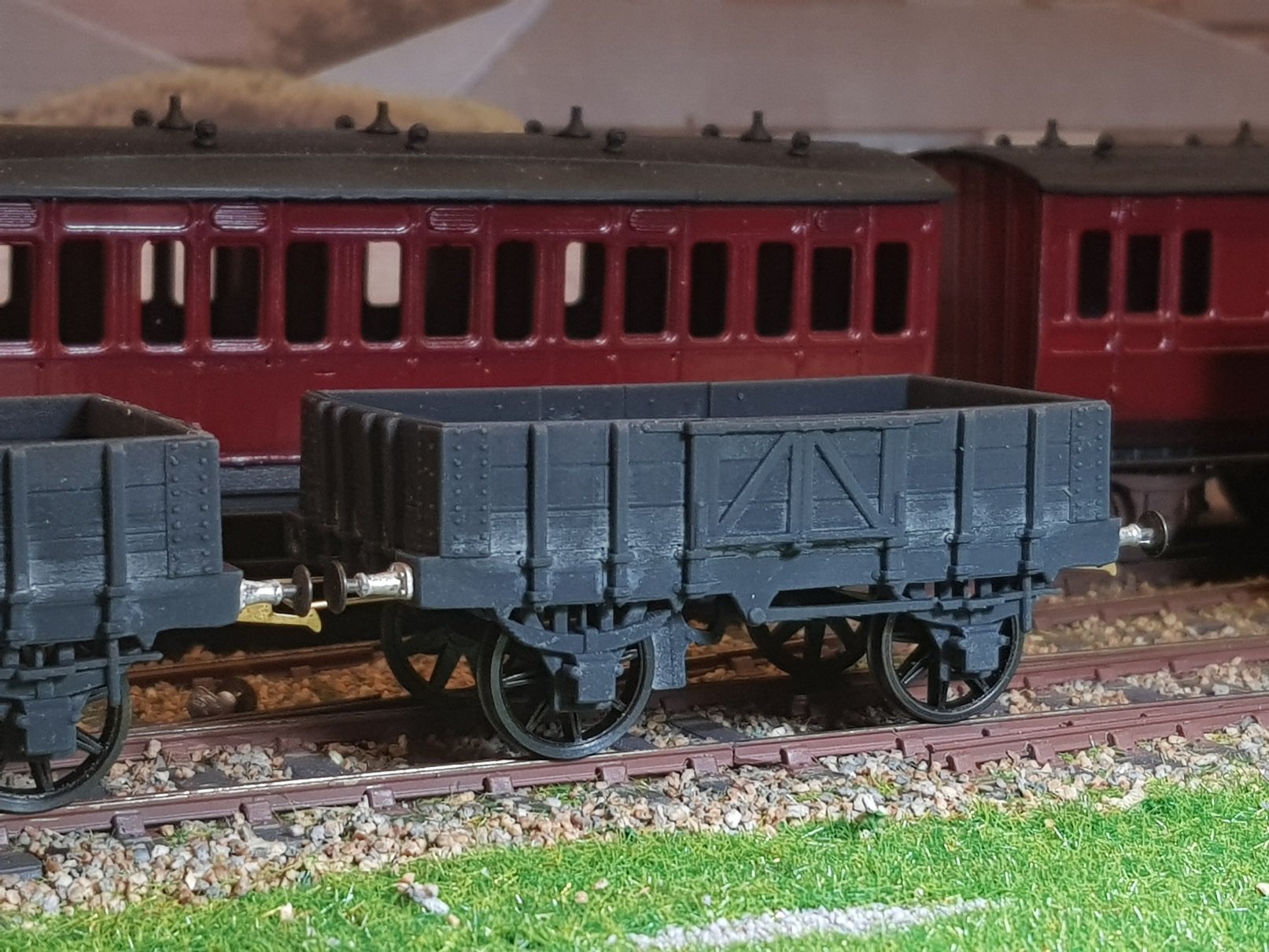
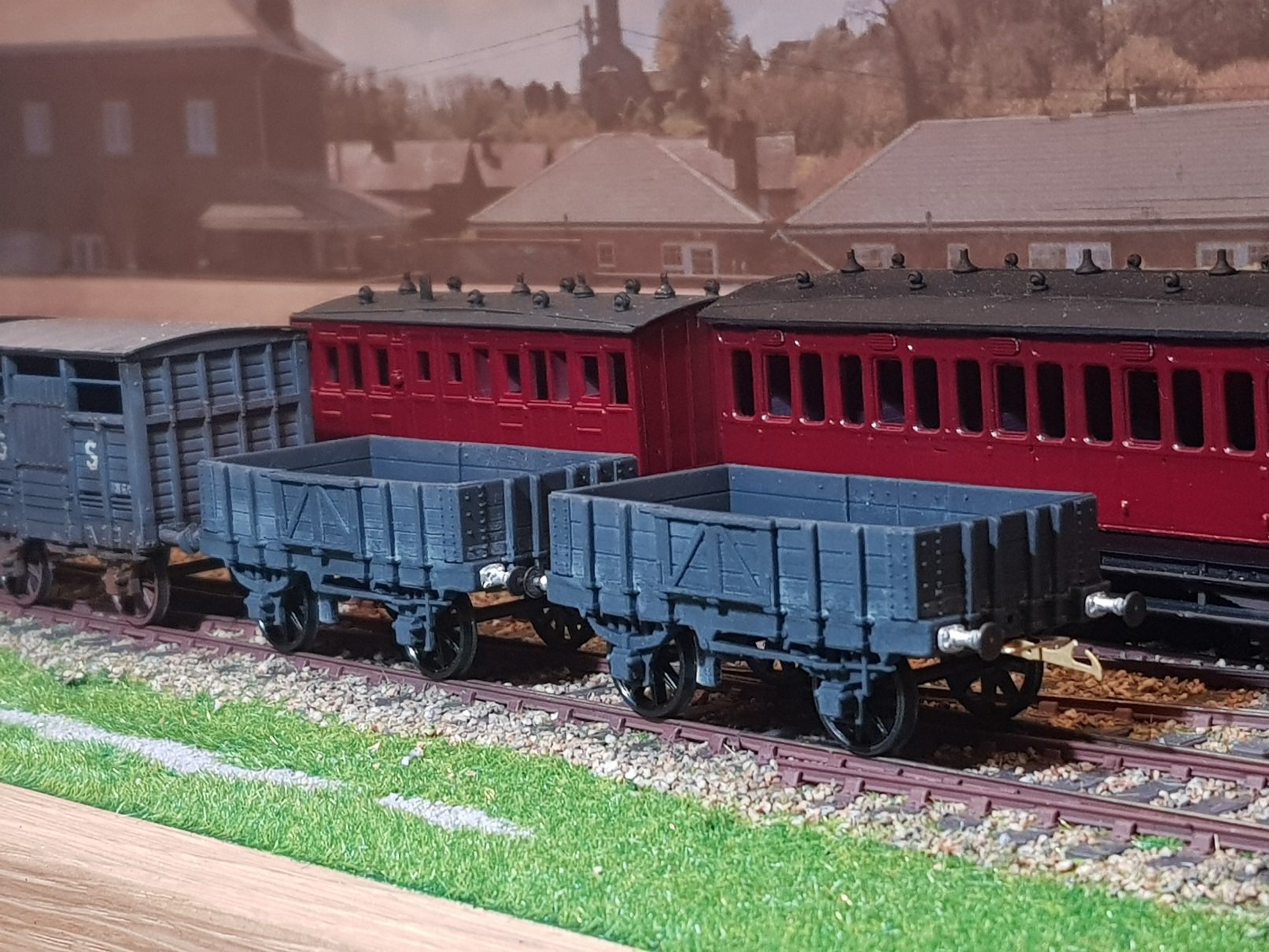
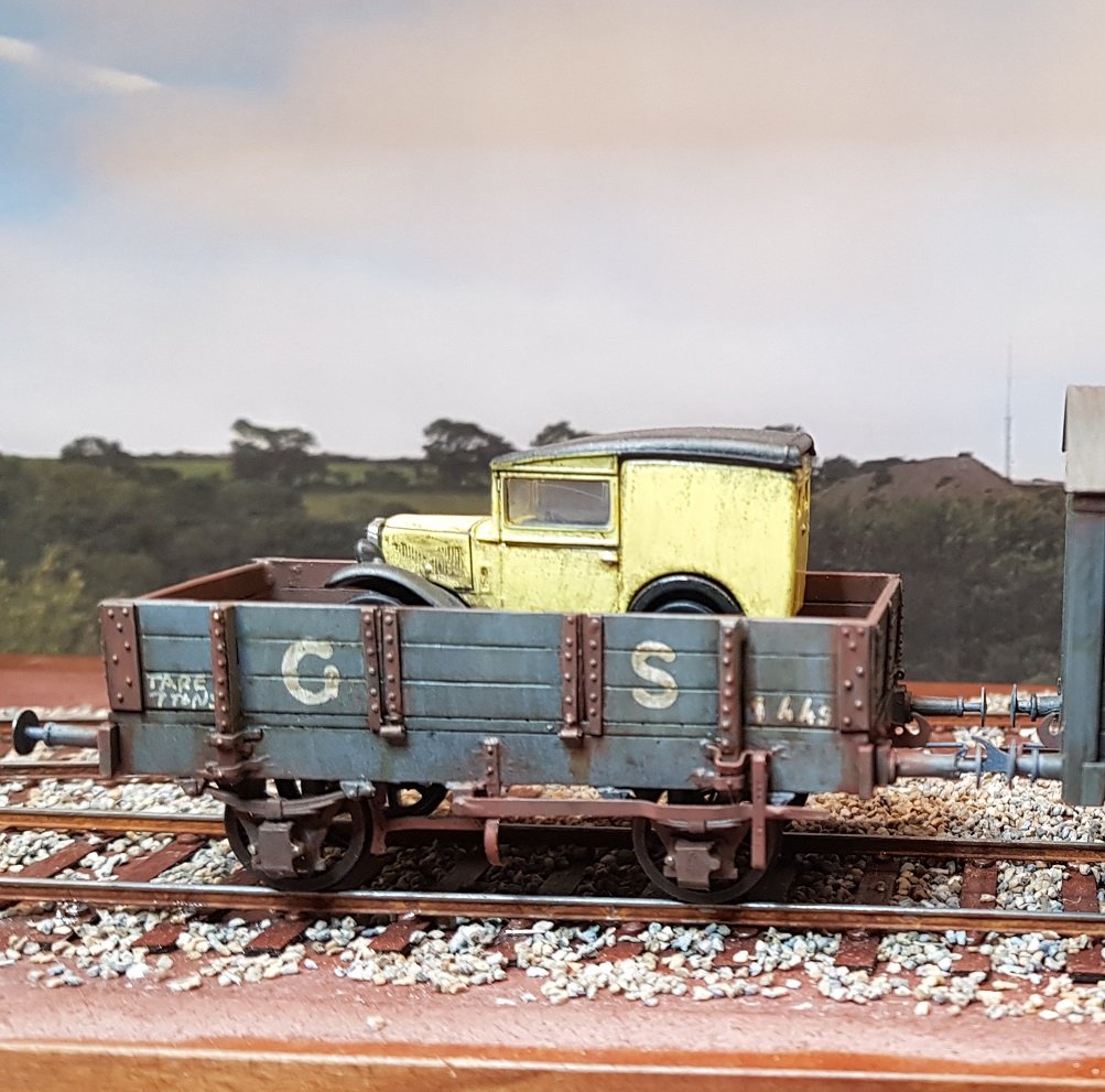
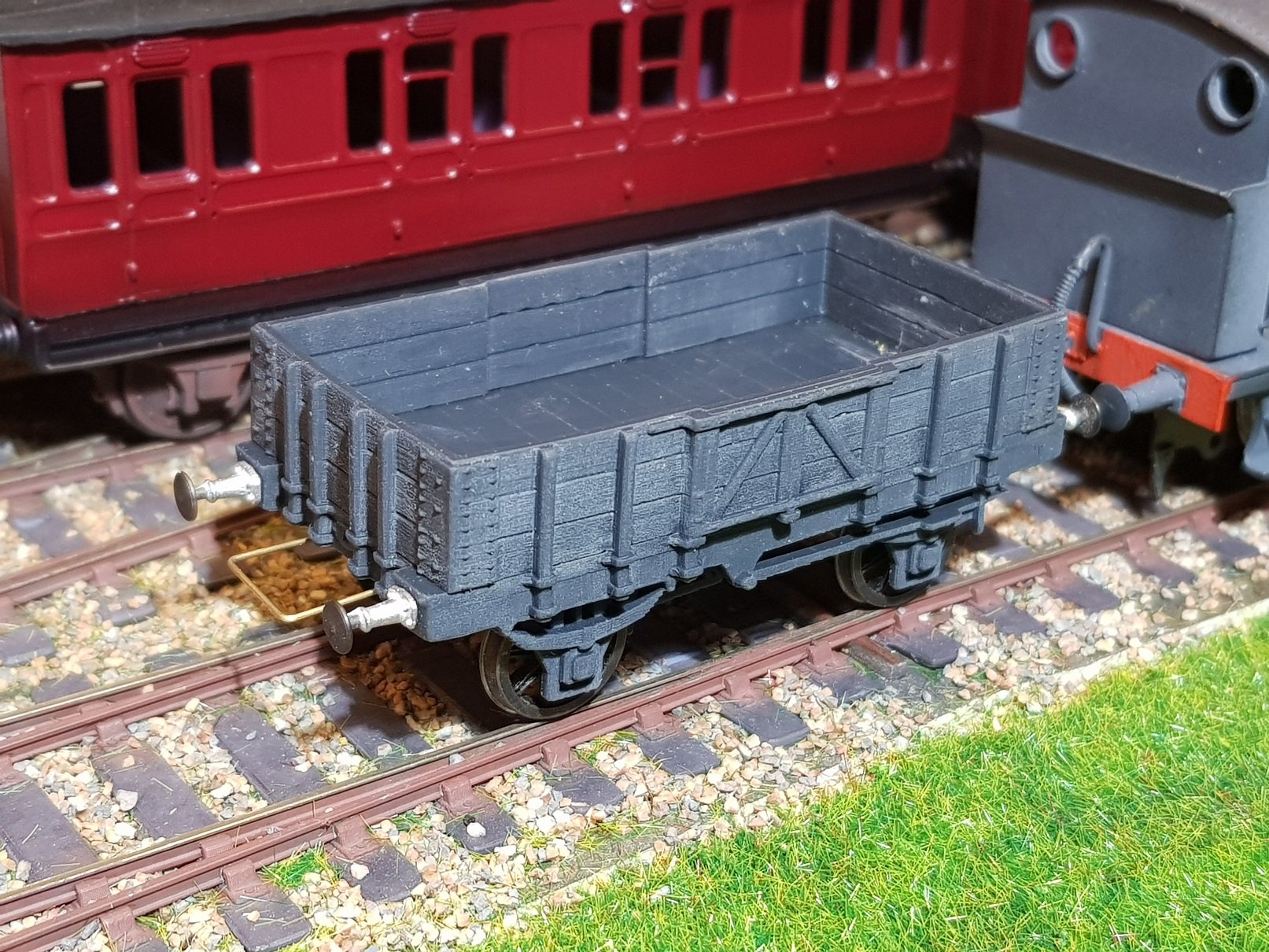
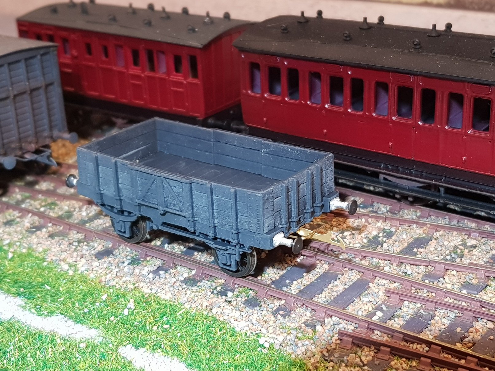
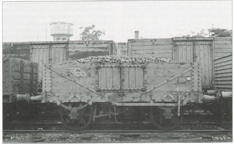
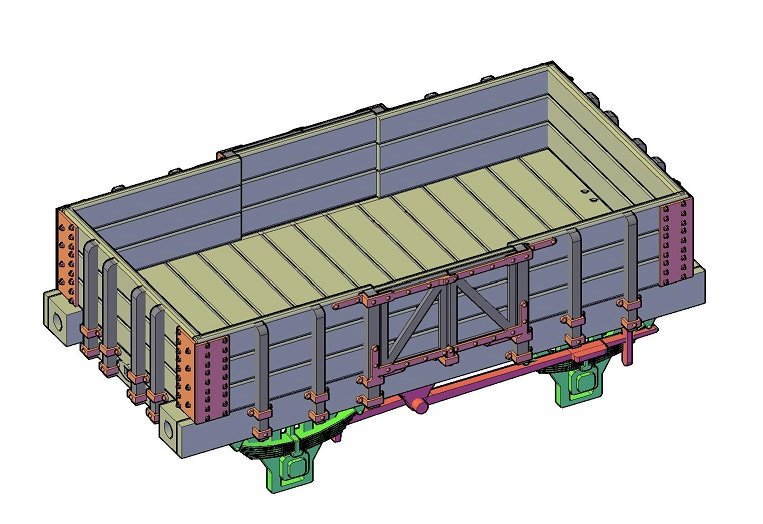
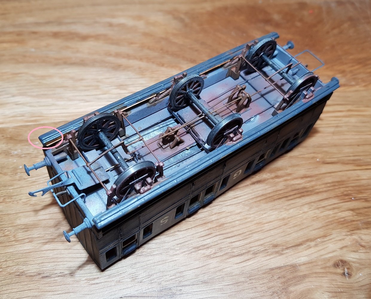
Back to wagons briefly. As part of the package of drawings I received from HMRS was a drawing of the 3 Plank wagon ordered by DW&WR in 1872. 40 of these wagons were ordered from two suppliers, 20 of which were supplied by Metropolitan Carriage & Wagon Company, and this is a development of their drawing to form a model. These wagons were re-built by DSER in 1907, however I have elected to model the original version, mainly because the drawings were available - one slight change I have made is the use of a slightly smaller brake block; I may amend this to the larger shown in the original drawing for future prints. The drawing was developed, and once again corrections applied to the minor disrepancies between the drawing and the figured dimensions. In fairness, this drawing was much more accurate than the others I have worked with to date. A 3D model was developed to allow printing as before. This model had considerable detail, but one error I now see is the missing seam between the doors on the inside. I can introduce this prior to printing off some more. A print later, add some wheels, buffers and couplings we get: This has printed rather well and the corner plate detail which is very noticable on these wagons came out very well, as did the strapping at the base of the uprights. The rivet detail at the top of the door is not as good as other detail, so I may need to provide some additional supports to help hold the sides stable when printing. The top of the sides has bowed out slightly, but his can be adjusted with some deft attention with a hair dryer. These models respond well to heat from a hair dryer giving just enough time to move the side back into position & allow it to cool. (Side note: This may be something that will need looking at in the future - I may need to investigate what will happen if a model is left in the sunlight for an extended period.) Once again axle boxes have inset cones to take the pinpoint axles, holes added for buffers, draw hook and coupling points. I appear to have run out of hooks, so will need to order some more to finish this one off. As mentioned, the DSER re-built these in 1907 and changed them considerably, losing the distictive uprights in the process. Photo below is taken from Dublin & South Eastern Railway by E. Shepherd and Gerry Beesley. Nice wagon with some distinctive features which hopefully will show once painted & weathered. All for now. Ken
-
That's an excellent coach & I love the finish.
-
Why not. I have not given it a try, but may be worth running a trial print on one for the other models I have developed to see how they would come out. What track gauge are you working to, standard N gauge, or 10.5mm? The models would scale down from 21mm, so you may have the option of either depending on your axle pin to pin dimensions. Can you advise? Ken.
-
Self propelled cranes and small coasters
KMCE replied to David Holman's question in Questions & Answers
That is a clever layout - I really like the use of sector plate and hidden fiddle yard. That would make a superb layout with great operating potential -
Nice prototype and a superb model. What is interesting is the lack of falling loading door; it's something that came up recently in my research into the DSER version - it appears the the drop down door was only added to cattle wagons after 1900. If this premise follows through with GSWR, and given the single brake on the prototype above, probably dates that wagon to pre 1900. As to printing, I would consider developing a model and printing if there was an interest. Do you have dimensions / drawing for this, or did you figure from the photo? Once I have a basic CAD model, it should be straight forward to print either 4mm or 7mm as required. Ken
-
I think you may have identified the problems - I have on occasion added a stiffening piece inside a wagon or coach, something like 1.5mm x 1mm by the internal height or length as necessary. This has really beefed up the strength without being too obtrusive. I did this to strengthen the lower steps for the cattle brake I recently built. With reference to the CAD file becoming unwieldy - I found this happening to me, and it drove me mad. I traced the problem to the history associated with the objects as they are created. If you hightlight (or select) the objects, right click and select properties. There may be lines or surfaces etc that are selected as part of your selection box, so if the pull down box at the top say All, pull it down and select 3D Solid. Towards the bottom of the properties list is Solid History - in the HIstory pull down box, change this to None, and Show History pull down box, change to No. This should free up the model and allow you work with it without the long delays - worked for me anyhow. Hope this helps. Ken
-
Self propelled cranes and small coasters
KMCE replied to David Holman's question in Questions & Answers
David, For boats, try here http://www.tradboats.ie/index.php I found it a really good source of information, particuarly on small to medium boats all around the coast. When you mention self propelled cranes, do you mean a locomotive converted / built as a crane, ala the NIR version (with the hole in the boom for the chimney), or a self powered steam crane to run in a rake of wagons? Ken -
J-Mo, Can you clarify what failed in the print, (are you resin or filament printing?). Over the course of my printing experiences, I have had numerous print failures, and where the model was at fault was normally down to part thickness; other failures were normally a result of poor or insufficient supports. Some of the most stupid were due to lack of resin in the tank - normally after a run of prints and not topping up in time!! Without seeing your CAD model, it's difficult to comment on its complexity or recovering from glitches as you put it. If you can elaborate, I can try to help, if it is of interest. Ken
-
Wexford Model Railway Club Festival Open Day 2021
KMCE replied to Irishrailwayman's topic in What's On?
Qu'elle domage, I was hoping to finally meet you there!- 98 replies
-
- 1
-
-
- model railway exhibition
- trade stands
- (and 3 more)
-
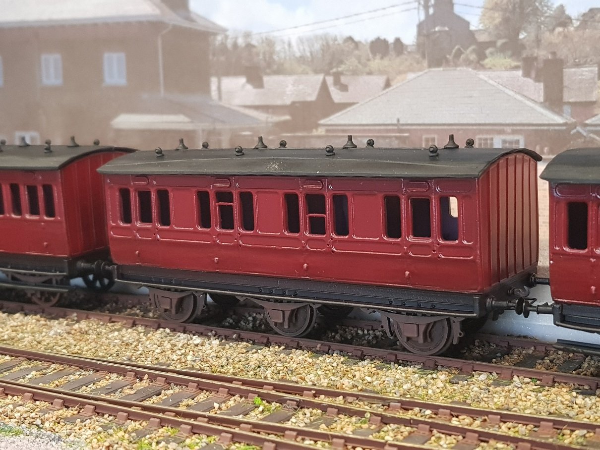
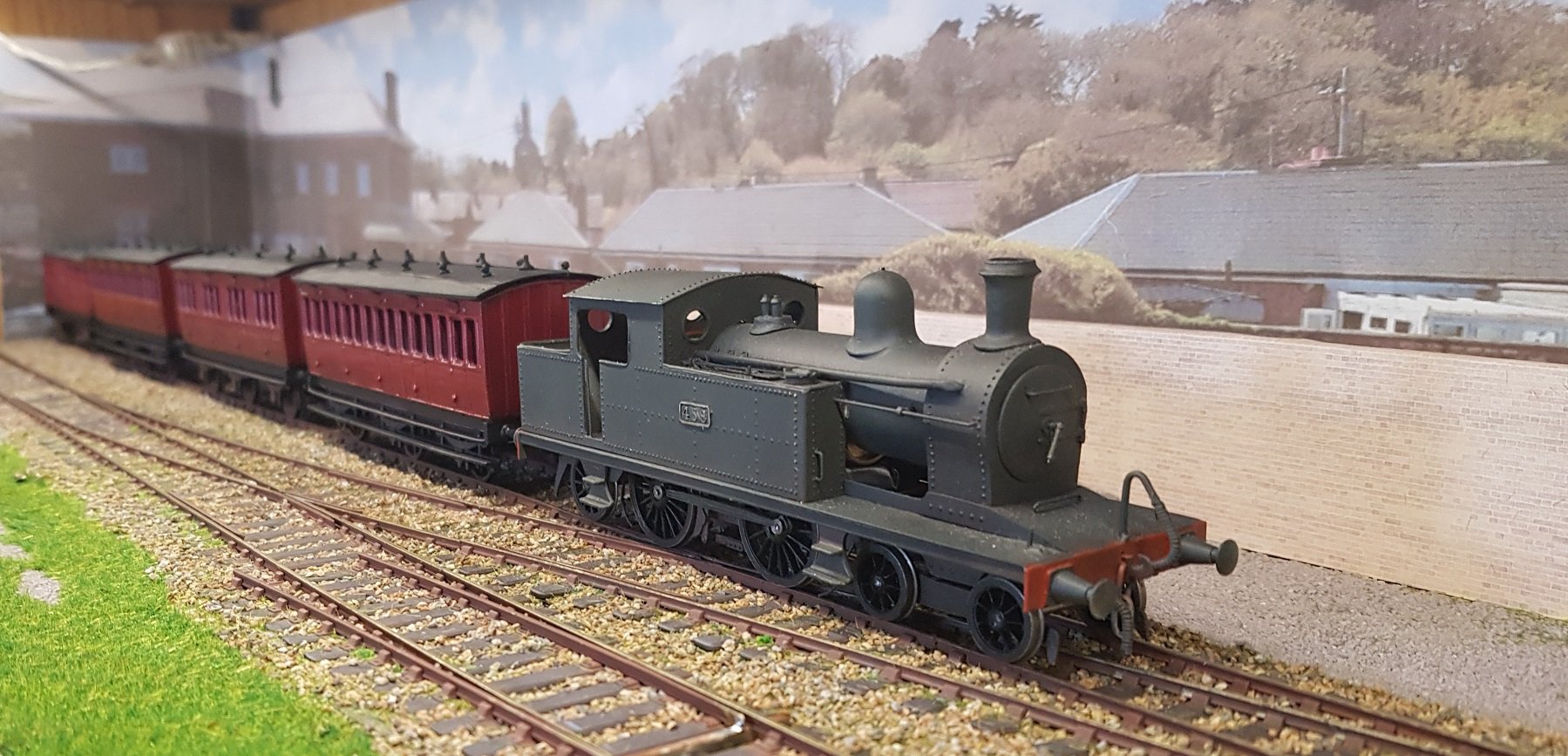
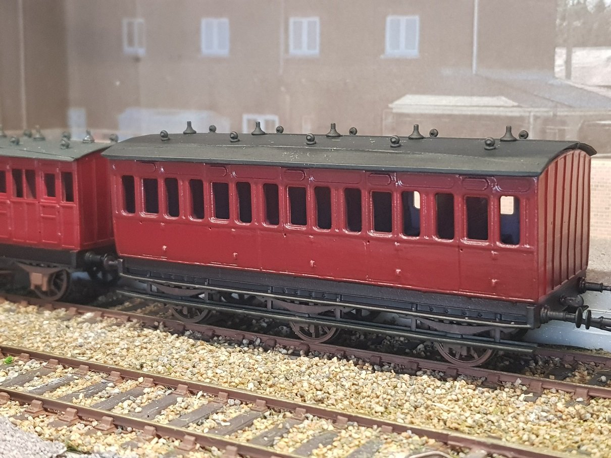
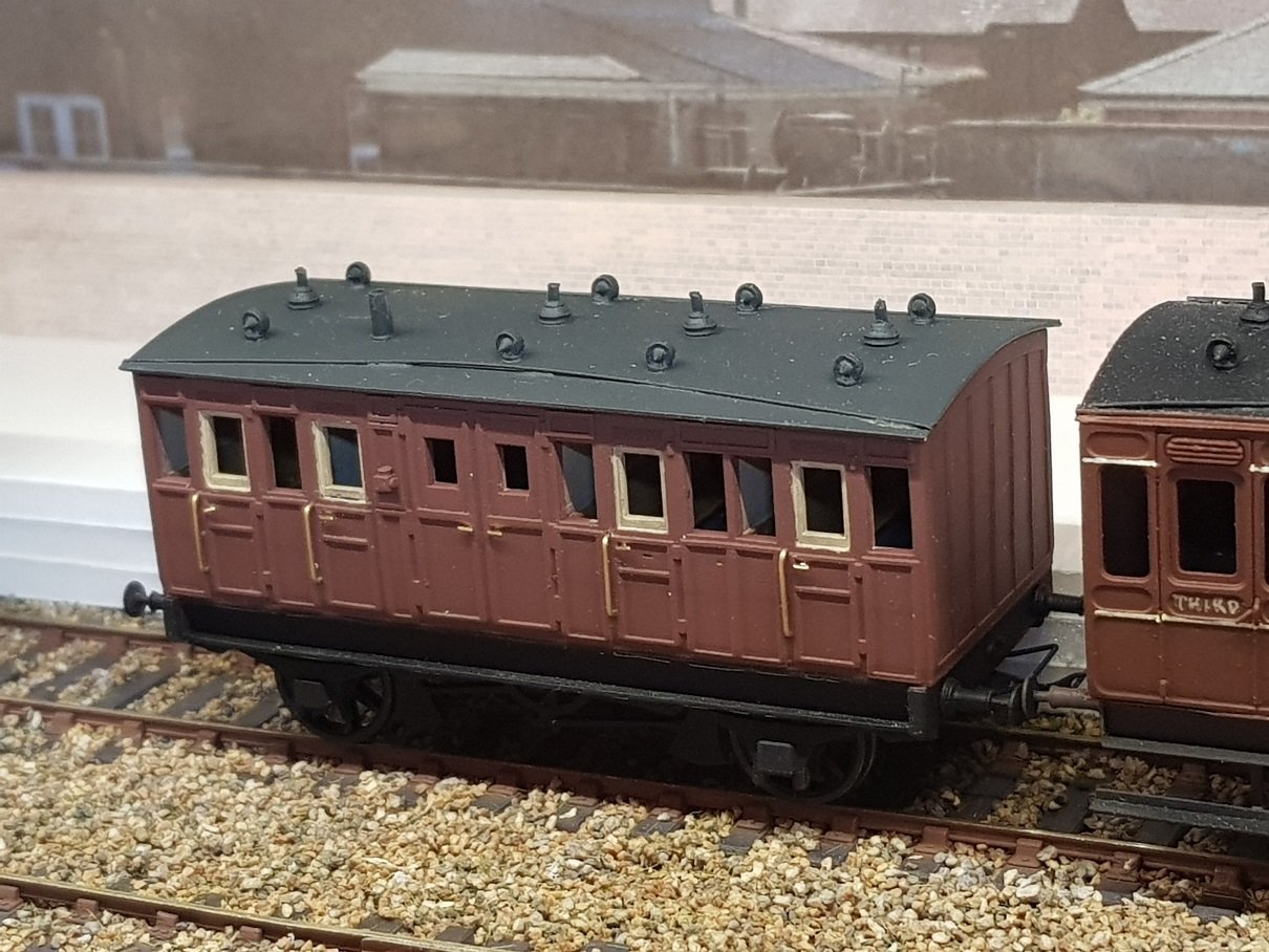
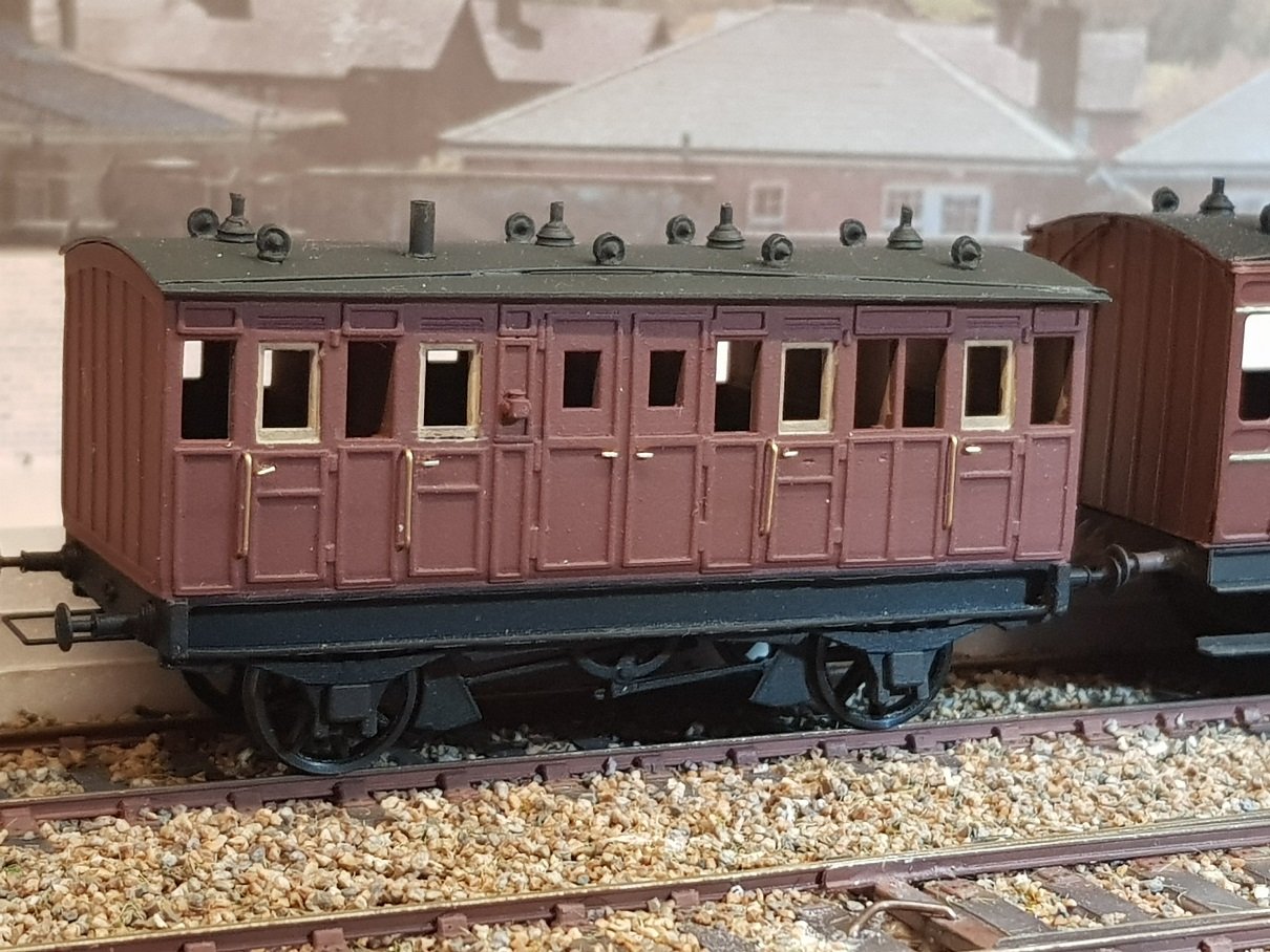
The advantage of the CAD process, is that once a model is developed, it is not too difficult to expand the range. So given we now have a 27' chassis, it makes it easier to find coaches what were built to this dimension, and looking into the records we can find a first and third that can be built up from this base. A first No. 48 built by Grand Canal St. (GCS) in 1896 fits these dimensions, and thankfully there are some photos of this coach, which helped the development process. This coach was converted to 3rd in 1931 - but for this exercise, we will stay as a 1st. The 27' chassis also allowed for an early 5 compartment 3rd, in this case No. 1 built by Brown Marshall & Co. in 1892, which was subsequently converted to a sleeping van in 1927. Again we have photos of the coach as 137A (sleeping van), but for this exercise, we will keep it as 3rd No.1. Given we have a model, and there is space on the build plate, why not build two, and we can pick a number betweeen 2 & 12 for its number. What is most interesting is that some of these coaches were used in the "cockle train 1925/6", which to date I have been unable to uncover any information as to what exactly this was. Any information others may have would be most appreciated. A quick respray of the 4 wheel 3rd brake alreay shown would add to this train. Paint was a solvent paint mix from Vinny Byrne which sprayed very well but needed a lot of clean up of the airbrush. Colour and paint is very good, but not sure the work required with the airbrush is worth it, particularly given the change to acrylic for other colours. Perhaps this is why others have invested in mulitple airbrushes?? Looking at the images, the paint may be too thick as the door relief as partially dissappeared - I may need to scribe these slightly to reinstate the detail. Not a big issue, but needs to be resolved. For this project I developed the roof for 3D printing, including lamps and torpedo vents. This did take a number of efforts, as the initial prints were too thin which resulted in wavy edges. For these models, I increased the thickness, but filed back the edges to thin them slighly so they do not look overscale. The difference between the ends and sides of the 6-wheelers shows the thickness difference. Given the reduction in work between the brass version and this one, I can live with the slightly over thickness on the ends. Put all these together and we get a nice DSER style commuter train. Still a bit of work needed to add glazing, door knobs, handles, weathering etc to finish, but very pleased with the results thus far. Will bring these along to the show in Bray on Sunday for anyone interested in attending. All for now. Ken
-
That is some collection of material - hope it all fits & best of luck with the show. Most importantly - have fun!
-
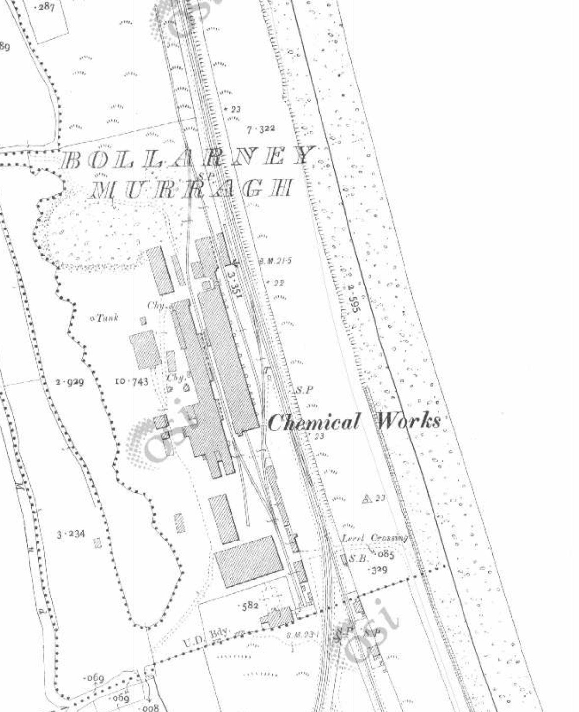
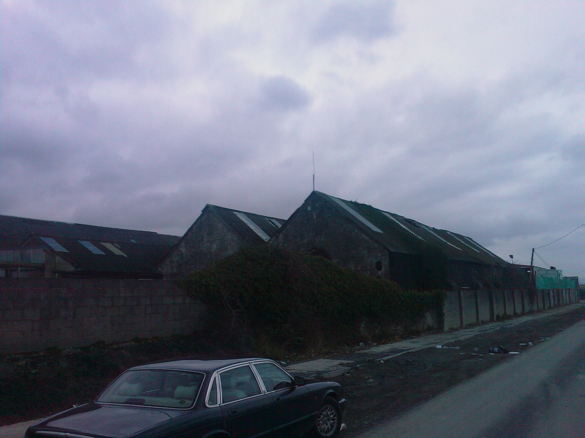
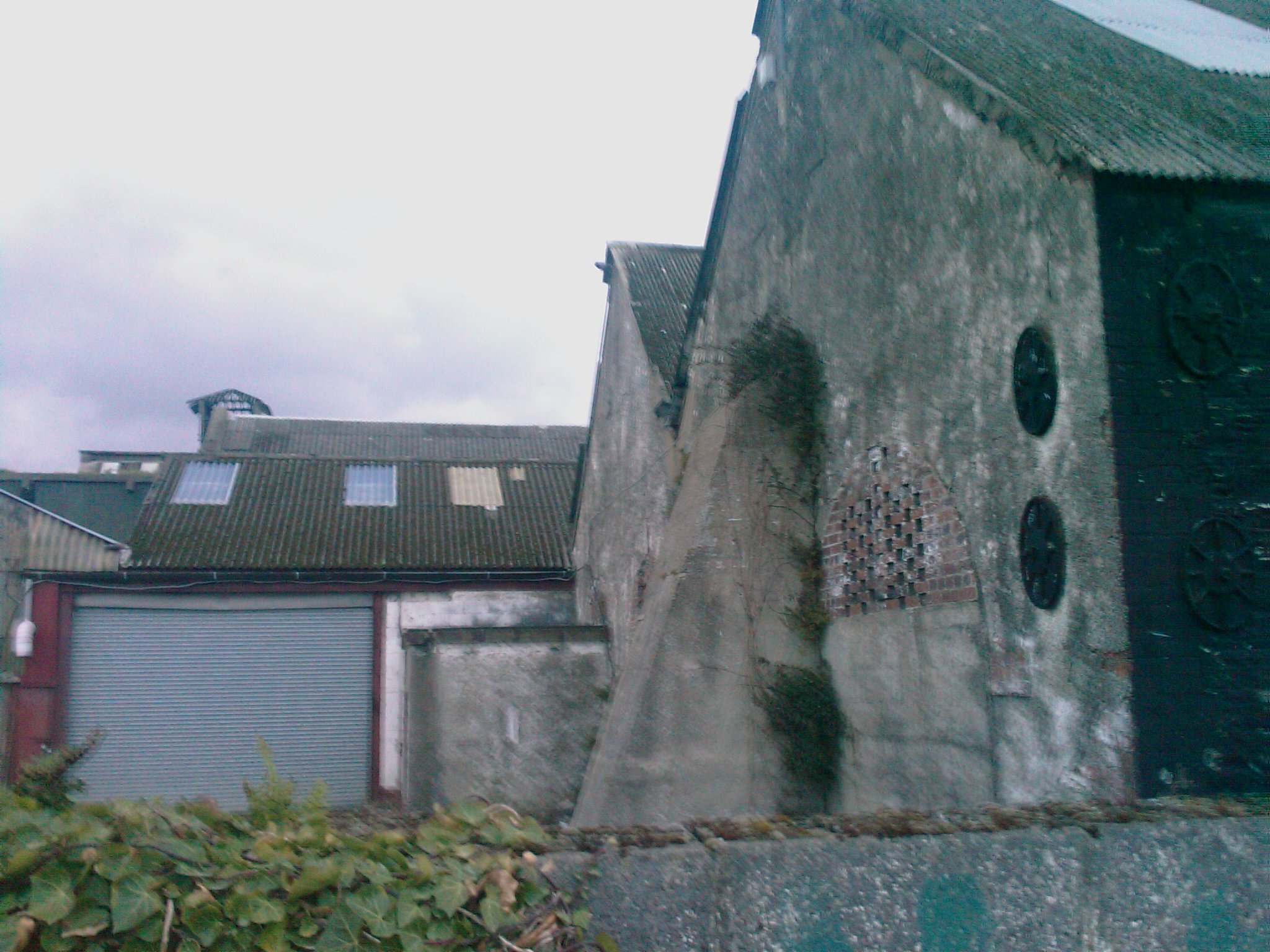
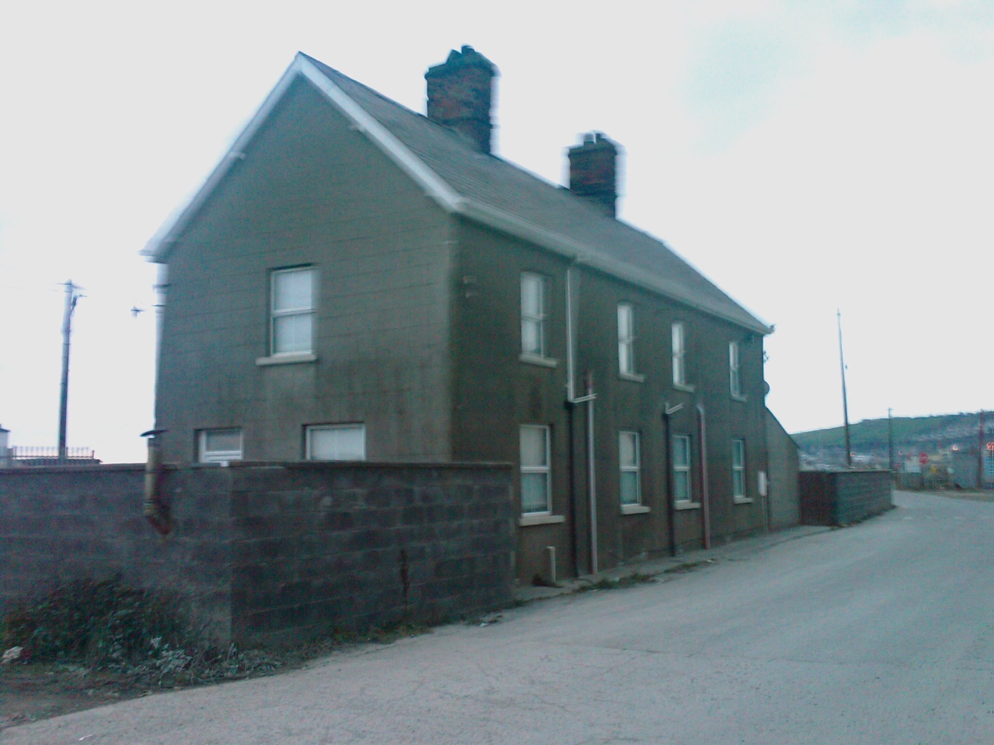
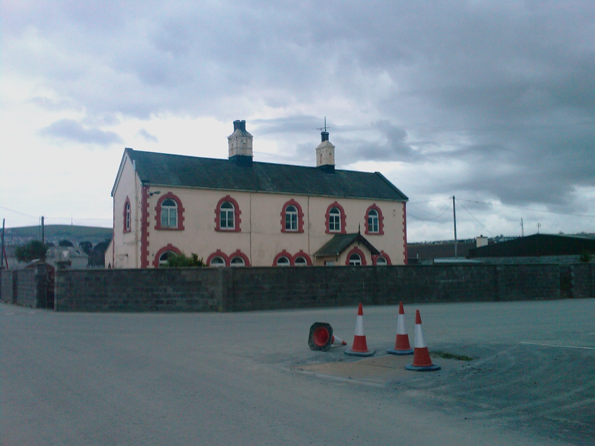
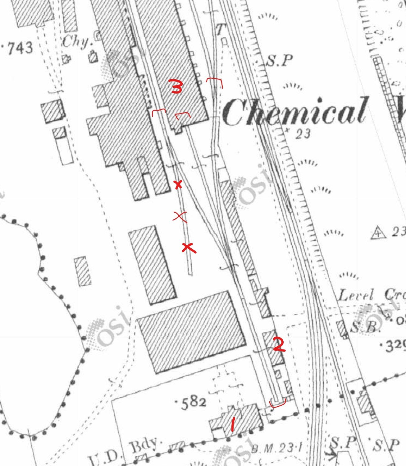
Tony, Part of the chemical works in Wicklow would provide the shunting puzzle you are looking for with a little creative licence. The section shown below will provide the necessary sidings and the buildings can be used to hide the ends of the sidings, whilst the loop onto the main line could be "closed" with a level crossing gate or similar. There are still some buildings remaining, although barely at this stage. I have some photos I took some time ago if they are of any use. House 1 House 2: Chemical plant buildings with bricked up rail archs just visible: It's a location I had in mind for some time, as we do not have many industrial sites in Ireland, however to do it full justice, a very large layou is needed & I just don't have space at the minute. Possible option? Ken
-
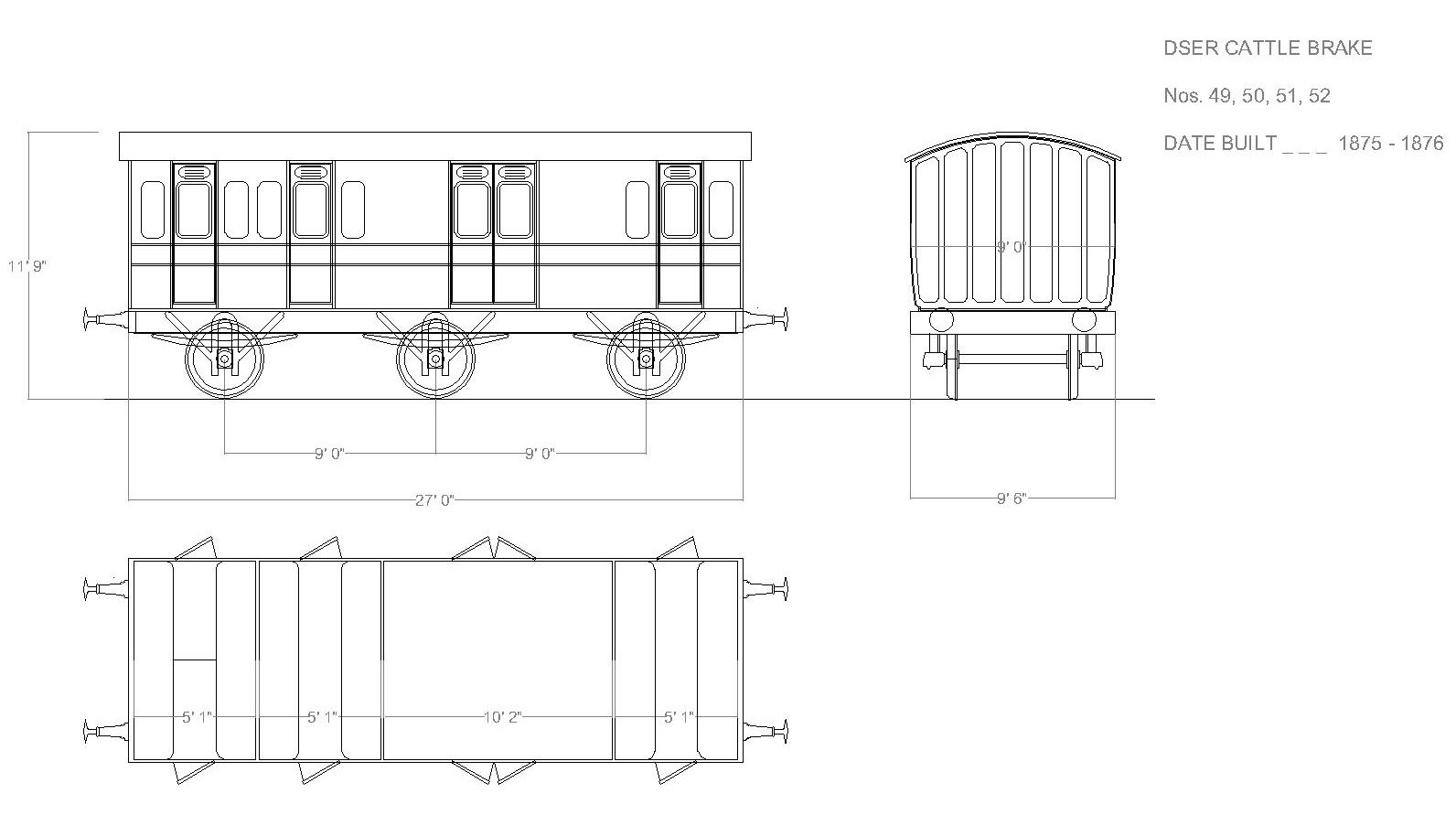
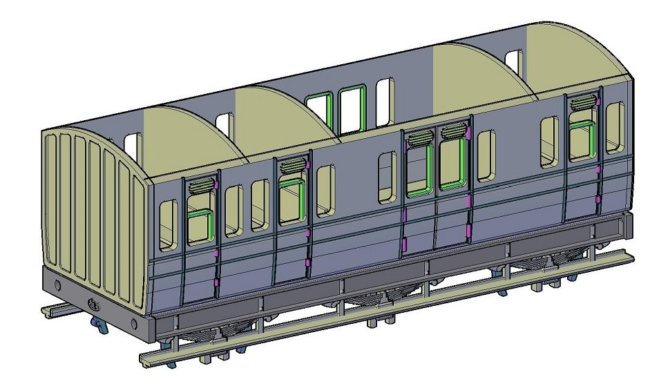
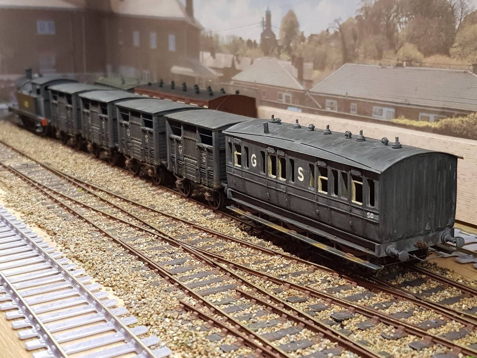
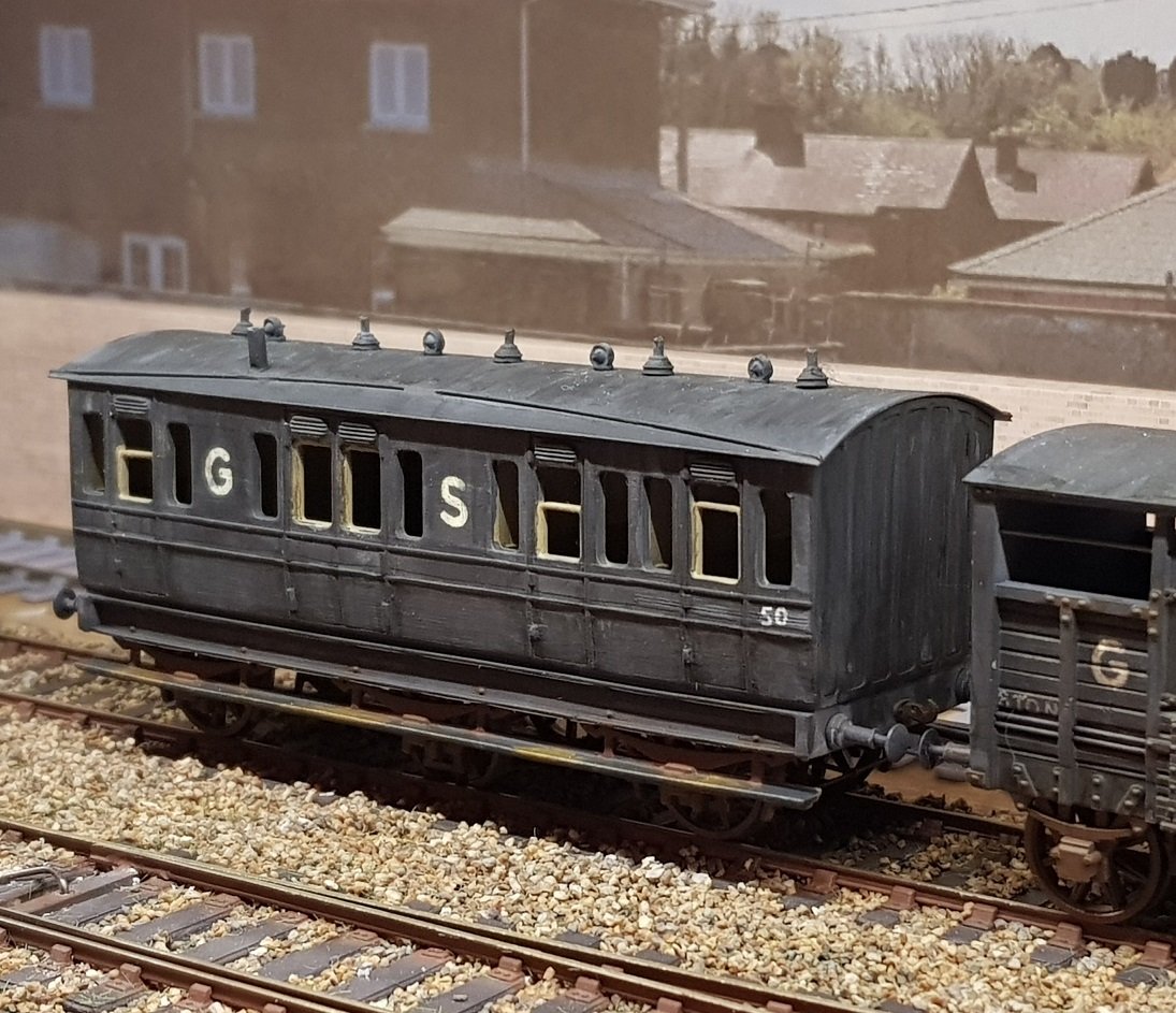
The Elusive one………. The Cattle Brake. This has been the most difficult wagon / coach to research and develop due to the complete absence of information in the form of drawings or photos. There is some written information as complied by E. Shepherd and Gerry Beesley in Dublin & South Eastern Railway, and E. Shepherd in The Dublin & South Eastern Railway (two separate books, I assure you). E. Shepherd’s comment on the cattle brakes is “Could not be found 31.1.60”. For a class of vans clearly designed for the cattle special and goods traffic the lack of information is lamentable. In 1875 – 1890 13 brake coaches were built at the Grand Canal St works and were referred to as cattle brakes, consisting of three 3rd class compartments for drovers and were ballasted as goods brake vans. They were subsequently re-classified as goods brakes in 1913 but maintained their 3rd Brake numbers until withdrawn. And that’s where the trail goes cold. I searched through other known information on 3rd brakes for dimensions, and similar coaches that were being built by the GCS at the same time and have deduced that the coaches were probably c. 27’ over headstocks with 3 x 5’1” passenger compartments and a 10’ 2” brake compartment. These dimensions were taken from drawings of 31’5” 3rd brakes (4 compartment plus brake) in my possession. As to the exterior finish, it would be a reasonable supposition that the exterior detailing would be rather plain given their proposed use as goods wagons, with some basic panelling or trims. An initial outline drawing was developed based on these suppositions: As this would be 3D printed, an associated drawing was developed. The springs and axle boxes were integrated into the model but are cosmetic as a separate compensated & floating brass chassis was intended to take 28mm pinpoint axles. 3rd coaches of this era ran with 3’ 6” open spoke wheels which would also match the goods traffic. SSM compensated W-irons were used with fixed axle glued in at one end and the corresponding compensated axle glued in at the other. A centre floating axle is suspended between front and rear axles by means of two 0.35mm phosphorus bronze wires and weighed down with a piece of lead soldered to the top of the W-iron. This flexibility and weight helps the axle to stay on track through corners and points. Brake shoes and lever frames were printed with the rest of the body, but some brass brake linkages were cut on the mill and integrated with 0.5mm brass rods to complete the brake assembly. Roof is brass rolled with ventilators and lamps added which came from SSM parts, as are the buffers. Painted in overall grey to match the goods wagons with lettering and numbering by stencil using white ink. Some initial coarse weathering has been applied, but more to be done. Glazing is still to be installed which will be done once weathering is complete, after which time the roof can finally be glued on. Some door handles and hand rails will need to be added also. And now for the Ts & Cs!! Given the considerable lack of information and the decisions made to create this model, it cannot be claimed in any way that it is historically accurate. Any assumptions made are purely my own, however I think this is a reasonable representation of a very elusive brake van. If anyone has any information on this particular brake van that would contradict, or improve on any assumptions/decisions I have made, I would be most interested in discussing. Does make a nice ending for a classic DSER style cattle train though! All for now. Ken
-
Timewise, it would need to be broken into the design element (CAD) and 3D printing. 3D printing takes just over 3 hours for one of these models, however you only need to fill the bath with resin, load up the code and press play, so can't really be considered work, as there is nothing to do until printed. Clean up (washing, support removal, clean up any flash) and curing takes about 1 hour. So for this model (3 iterations), there would be c. 10 hrs printing & 3 hours of clean up. Actual hands on would be the 3 hours of clean up & cure. CAD design is where the real work is. What is helping with newer models as I progress is the experience gained on the other models such as wall thickness, strapping & detail thickness, brake position, floor positionining, etc. Having a drawing of some description to start with is a bonus (as is the case with all above, save cattle wagons) as it helps to form the basic 2D model to begin with. The cattle wagon model may have taken over 40 hours of CAD time, particularly with the number of iterations & corrections, while the convertible wagon probably took 10 - 15 hours. The Drewery railcar probably took 20 - 25 hours as there was some new learning to do, but the forthcoming Cattle Brake took 15 - 20 hours. I don't keep a record of the time, as I go back an forth as time allows. Once a model is developed, it is only printing time and printer plate size the limits multiple copies. I can run 5 cattle wagons simultaneously , but probably only 2 Cattle Brakes. I have decided that I will not print locomotive models for a number of reasonsl, but mainly weight. The resin models are very light (cattle wagon 20g) which need lead weights to bring to a suitable weight to ensure they run properly on the track. There would not be enough room in a 3D printed model (steam loco) to put in sufficient weight to provide adequate traction. My brass models (with weight added) weigh in between 200 - 300g & so have adequate traction. A 3D printed model, even with a brass chassis would be somewhere between 80 - 100g, which means a lot of weight to add. For now, I'll stick with brass loco models. 3D printing is good for multiple wagons / coaches, however I think locos deserve finer work in brass?
-
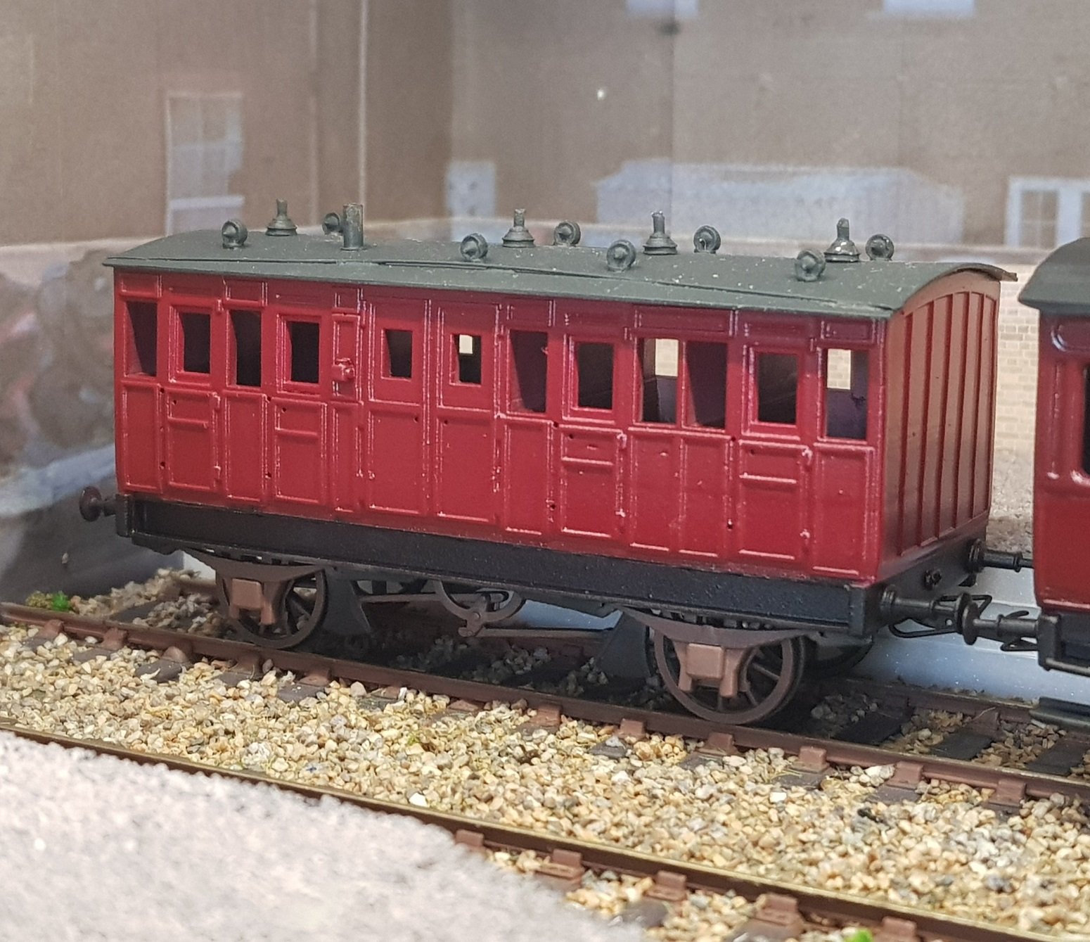
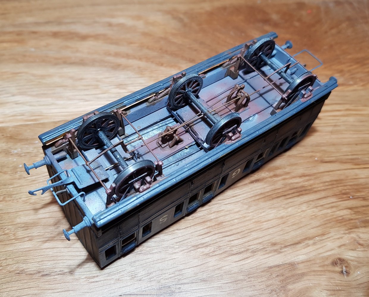
Moving on to other stock, I wanted to build a model of the 21' 6" 4 wheel passenger brake built by Metropolitan Carriage & Wagon Co. in 1878 for the DWWR. I obtained a drawing for this from the HMRS and developed my own 2D & 3D version. This like other models, this went through a prototying exercise, and I have settled on the Mk3 version. I magaged to get most elements sorted based on experience with other models. What made this eaiser to develop in 3D was that it was straight sided & thus reduced the amount of work in the CAD model. What is interesting is the size of the brake blocks - these are sized as per the original drawings. Last of these (1 of 4) was withdrawn in 1930, so did make it through to the GSR days. Nice little brake coach which still needs some tidying up, work on lettering, weathering etc. Ken
- 379 replies
-
- 10
-
-
-
Pure quality.........as always.
-
Ernies Massive Irish 1930's to 2005 Photo Archive
KMCE replied to Glenderg's topic in Photos & Videos of the Prototype
More of the former please...... Ken -
Leslie, Perhaps you can. We are starting to see bio-methane injection into the natural gas network. The gas produced from Anaerobic Digestion is being cleaned (or volume increased through hydrogen injection), injected into the gas network and sold on via "certificates" to those users who want to demonstrate their greeen credentials. As Mike noted above, CNG (compressed natural gas) in transport vehicles, particularly with the introduction of bio-methane provides a clean way of moving forward without the requirement for major modificaitons. LIkewise, a boiler can run natural gas or bio-methane without any changes - the whole purpose behind this is to create a renewable fuel as a direct replacement. It's early days yet with single digit percentage of bio-methane in the network, but very promising progress is being made. Hold on to that boiler for now! Ken