KMCE
-
Posts
540 -
Joined
-
Last visited
-
Days Won
29
Content Type
Profiles
Forums
Events
Gallery
Blogs
Store
Community Map
Everything posted by KMCE
-
Thanks for the comments guys - much appreciated. Colin it is 4mm - I haven't graduated to 7mm yet. Ken
-
In fairness, that's quite a recovery - it has a real lived in look. Nicely done sir.
-
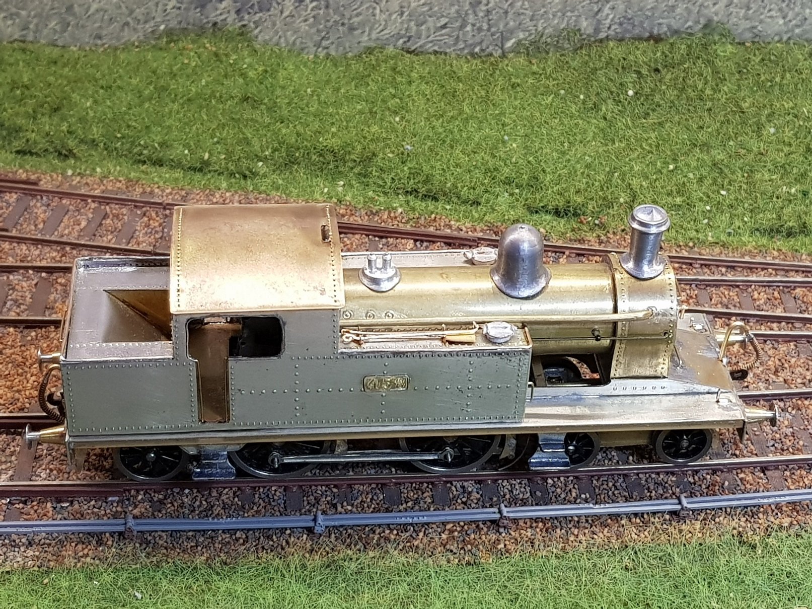
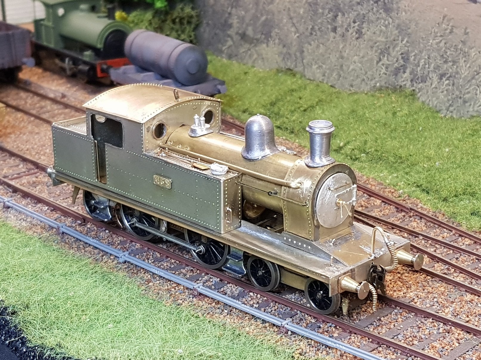
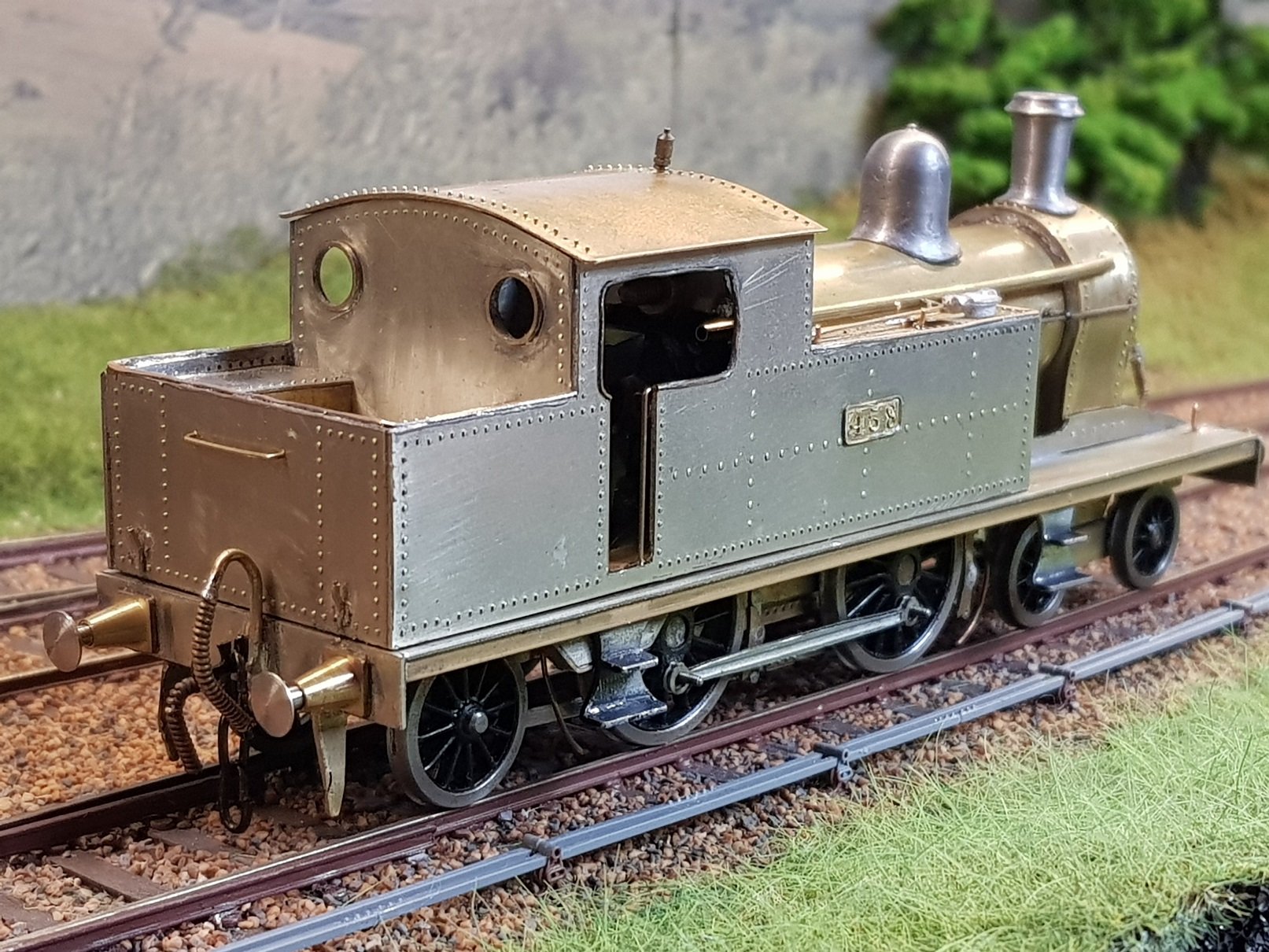
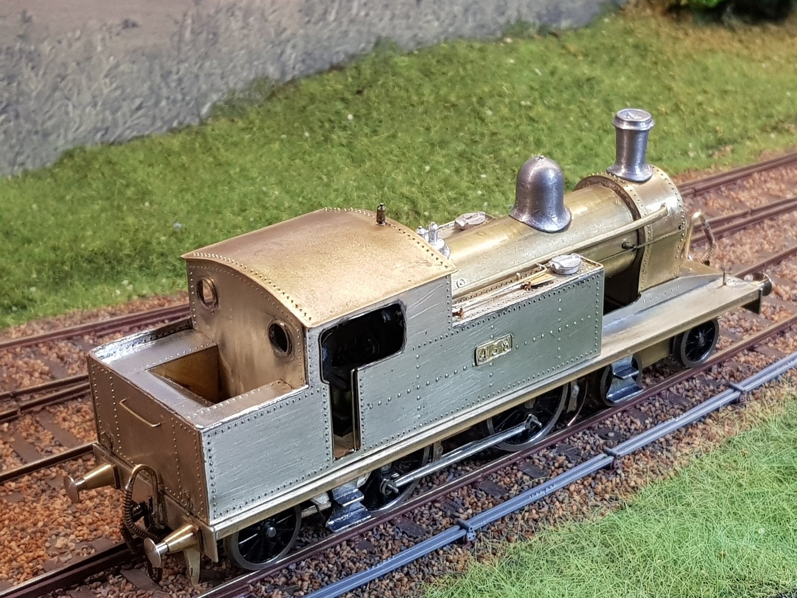
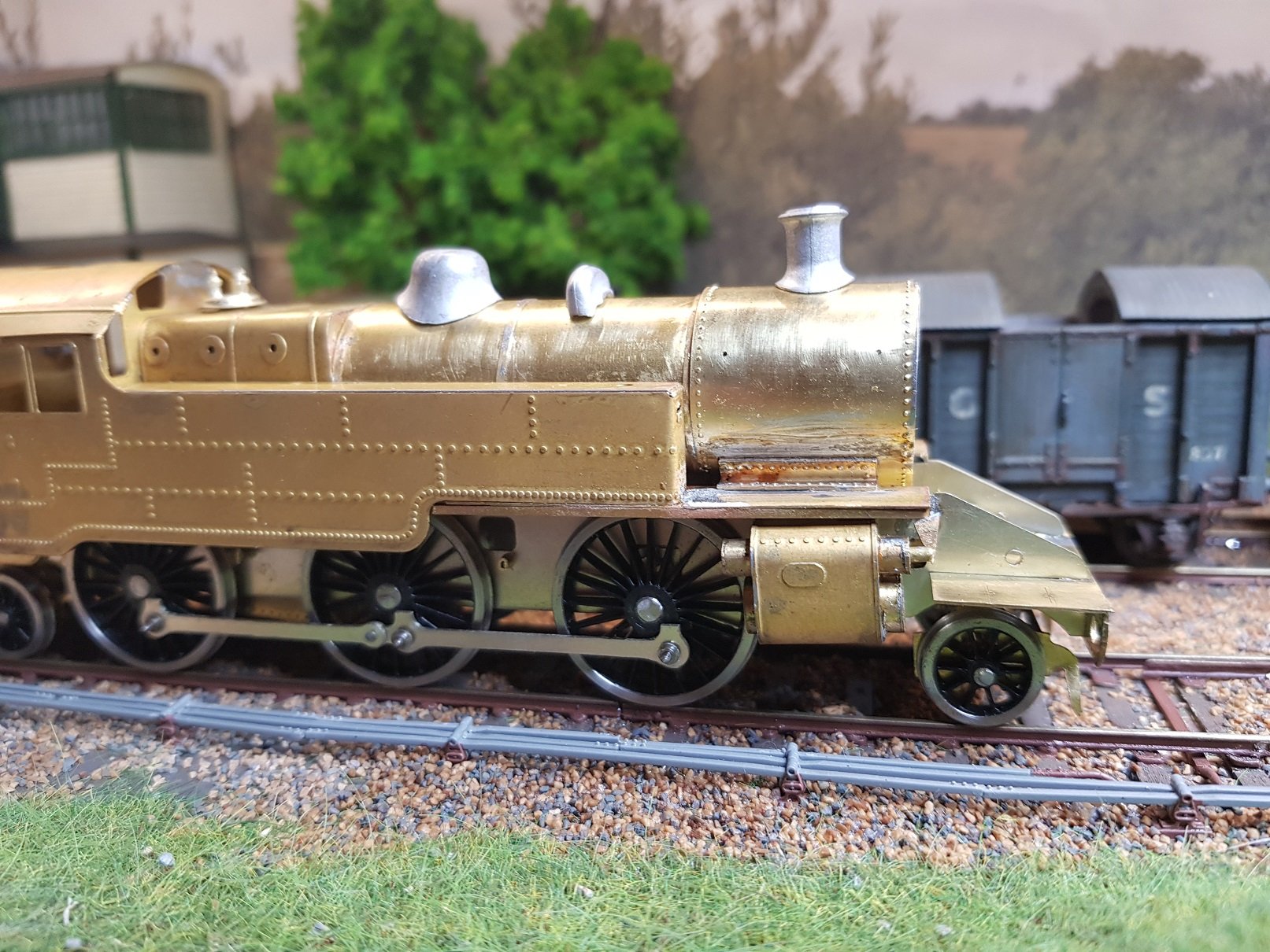
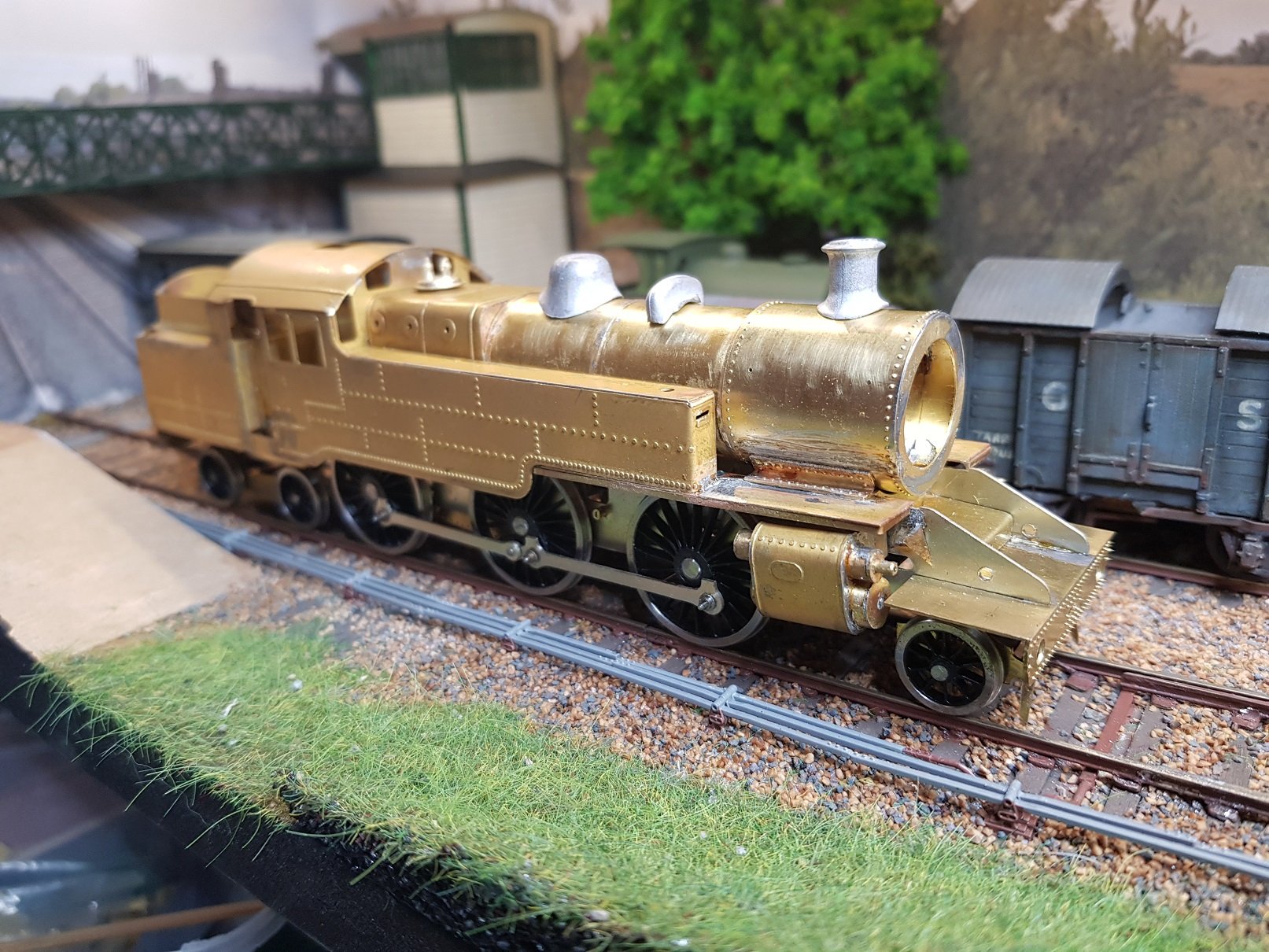
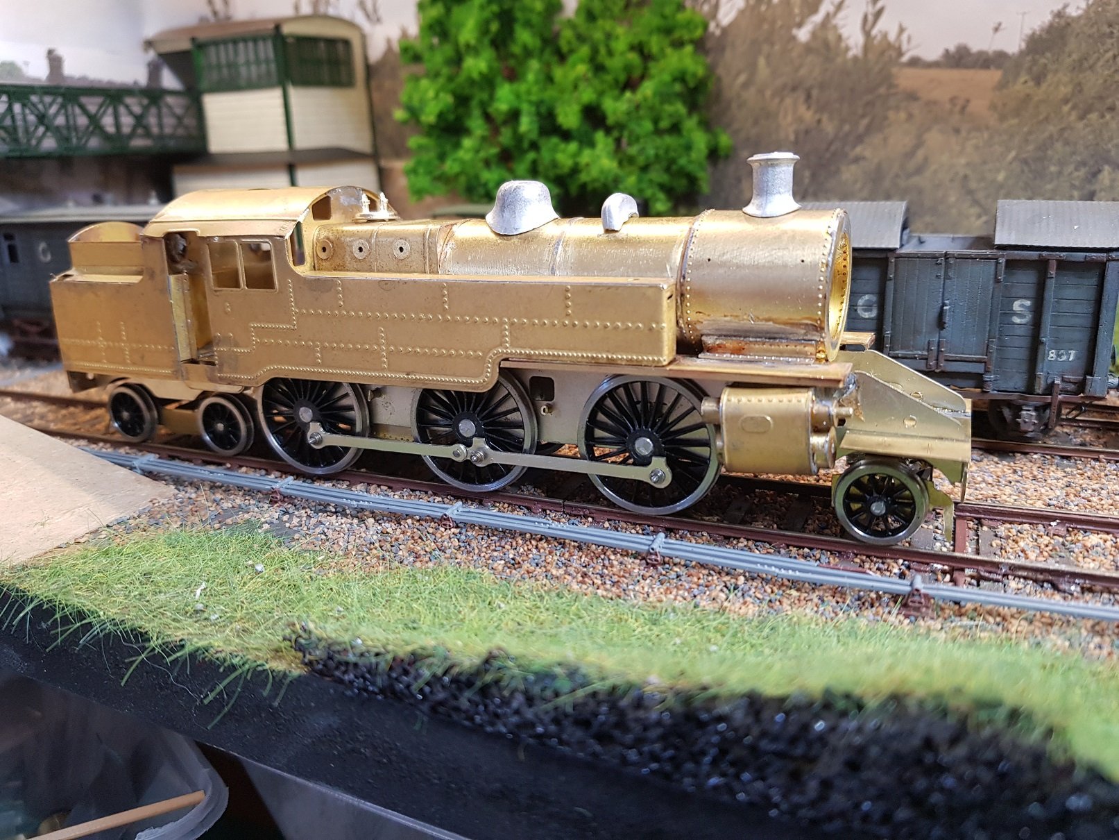
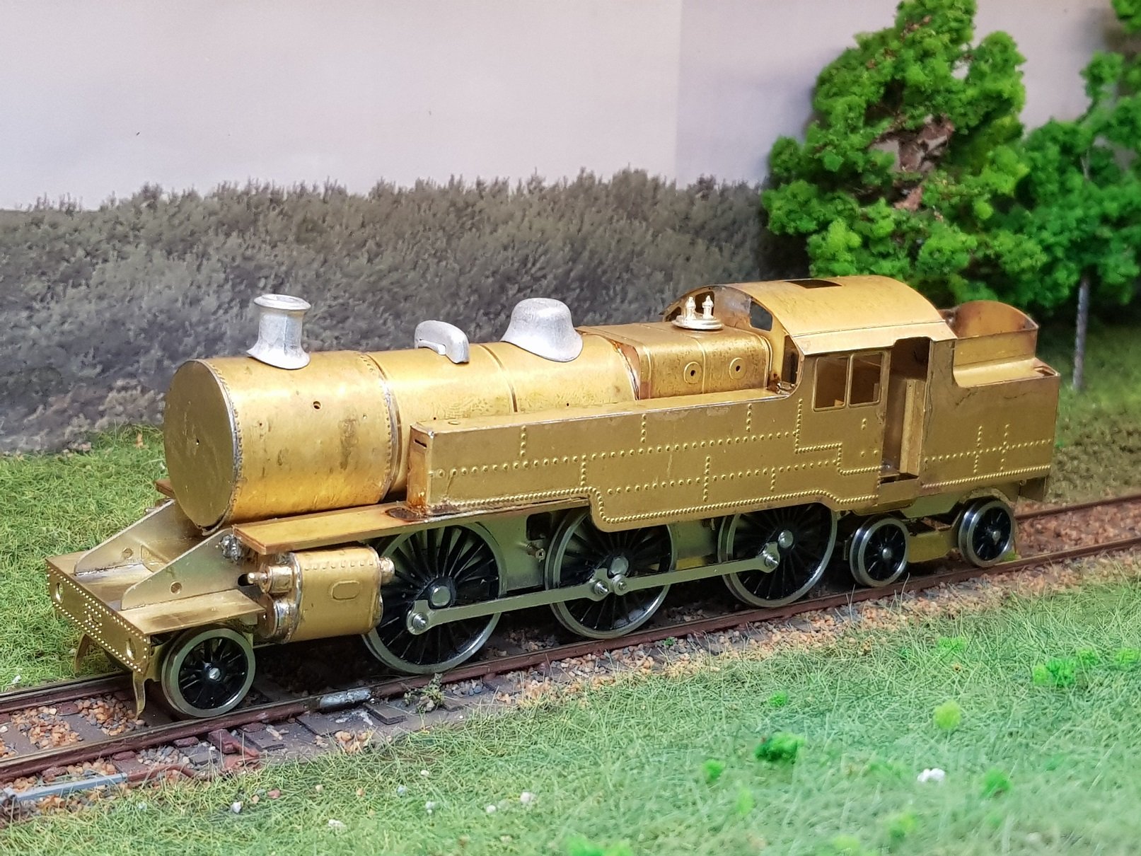
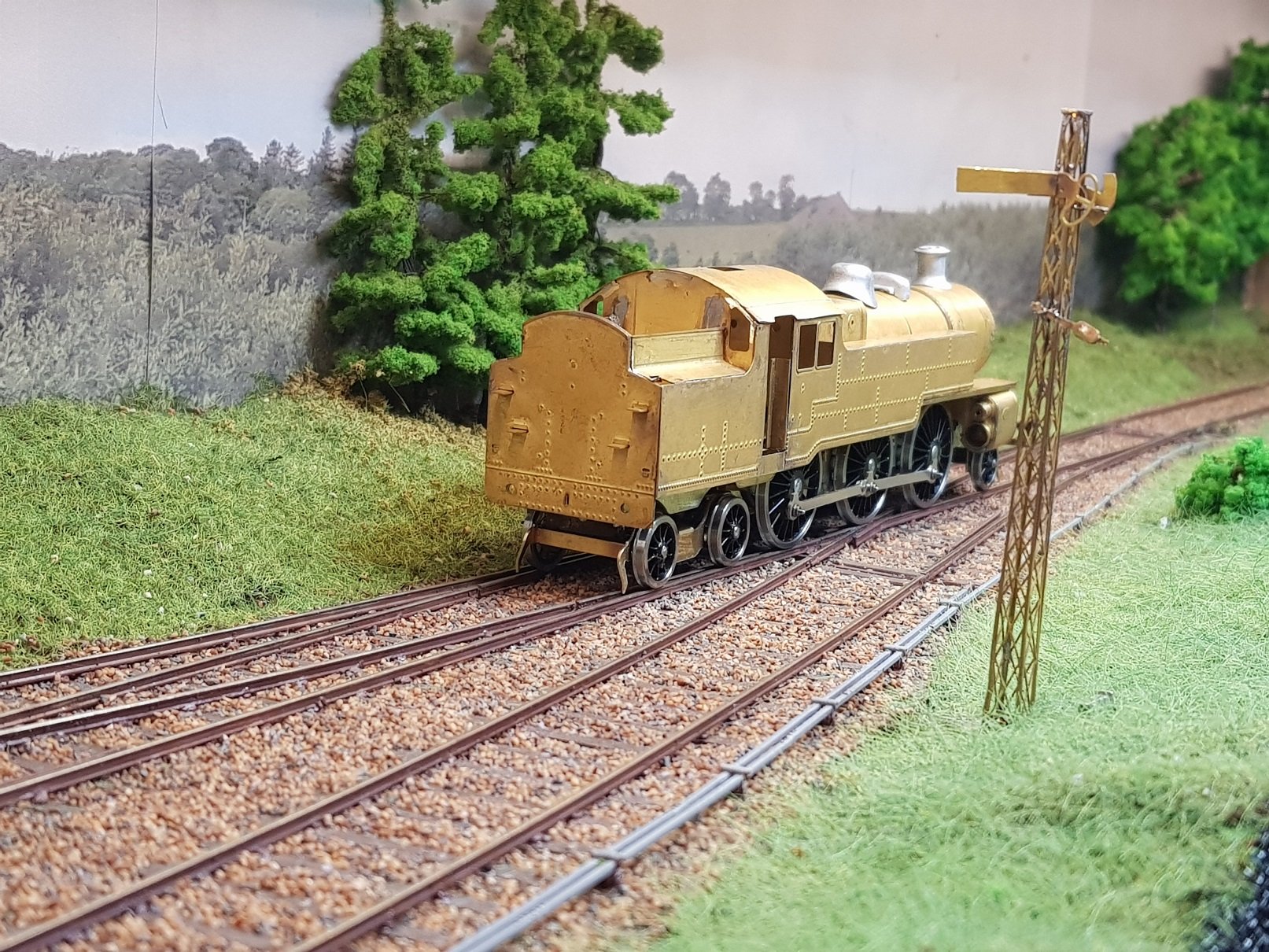
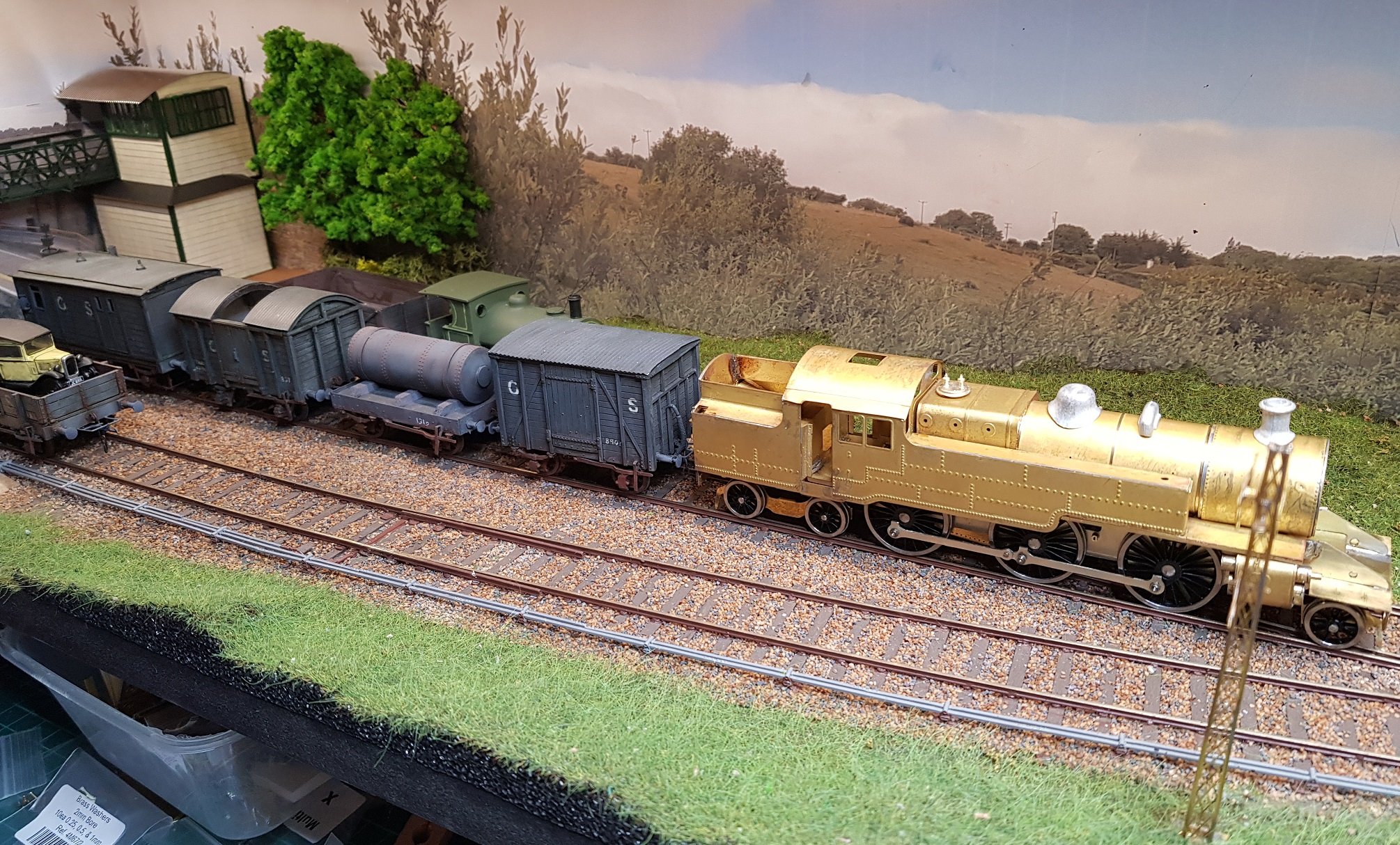
Wow, just looked at the date of my last post on this one - neraly two years ago. Well, its been sitting on the shelf looking at me, so I decided I would make a concerted effort to get it finished. In fairness, the loco was broadly complete and just needed some finishing details. Got around to over the last few days and a few quick photos before it goes to paint. Now begins the painting & fettling,, and hopefully I will have it with me on Sunday in Bray. Ken

- 45 replies
-
- 14
-

-

-
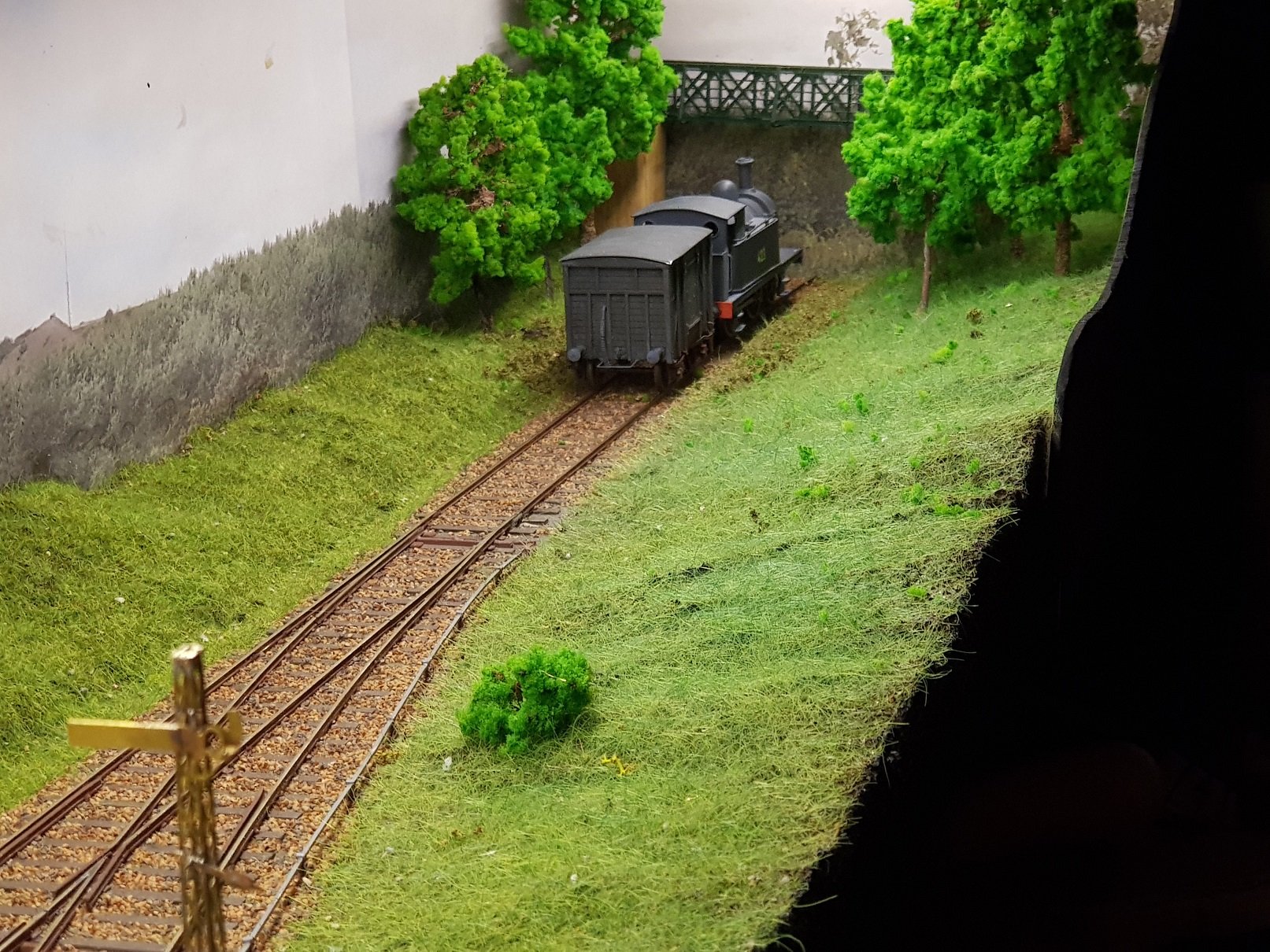
Well then, I guess my layout (project?, ongoing thingy?) Wicklow South could also be included. Ken
- 55 replies
-
- 11
-
-
-
Thanks Dave, Not sure which bit (or all) is not clear, I have photos of different stages of the build if that will be of assistance. Or if you prefer we can have a chat on Sunday. See you then. Ken
-
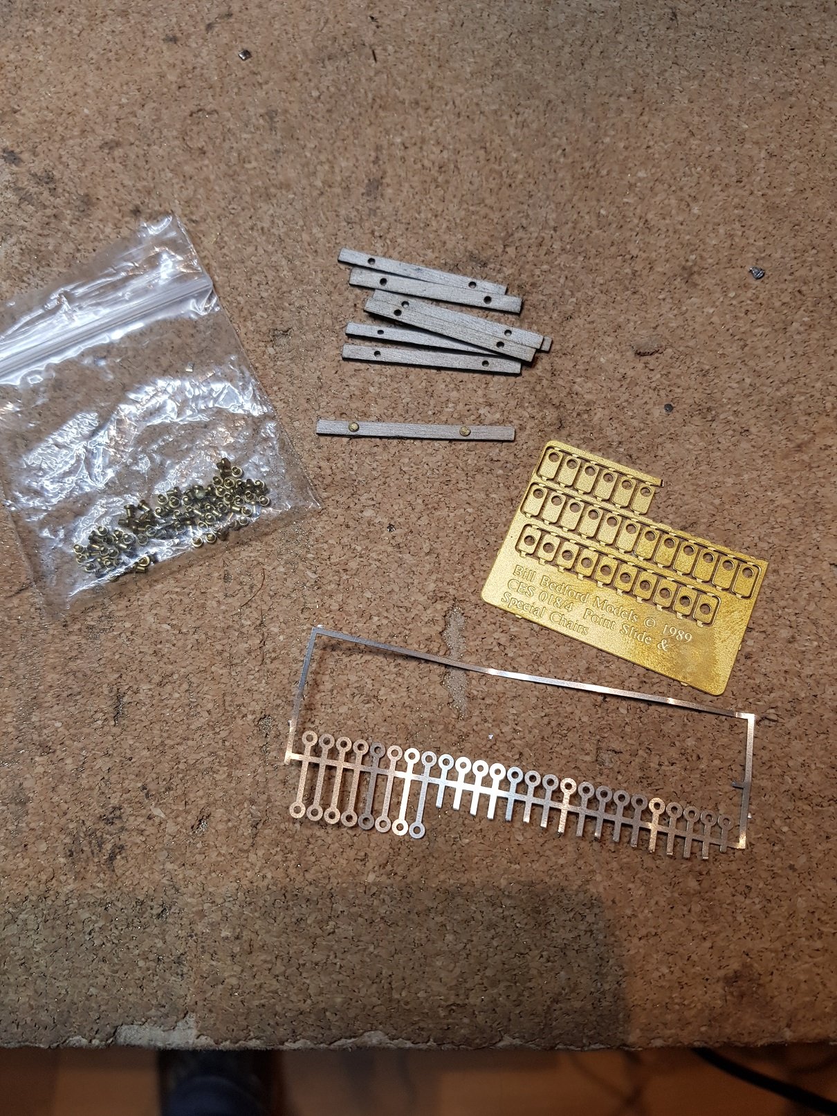
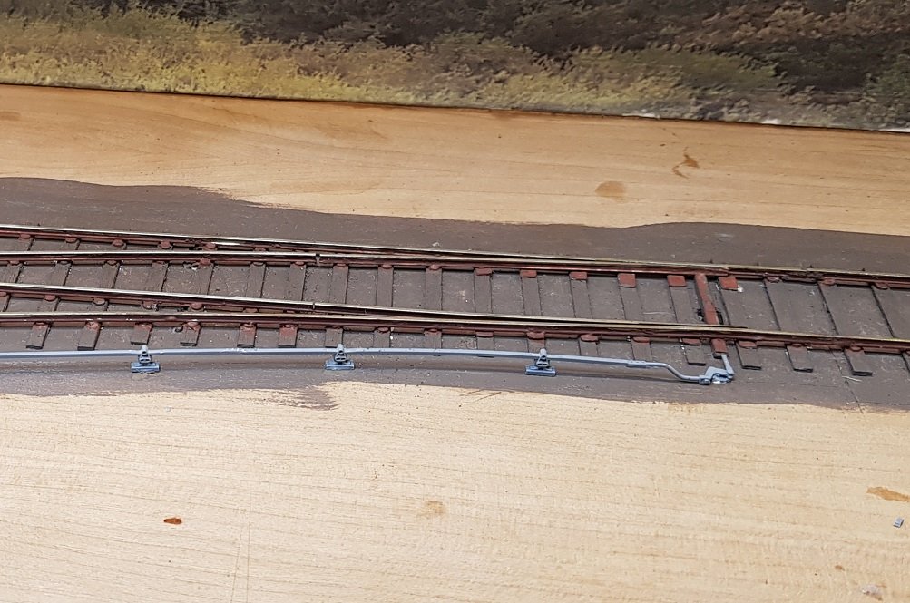
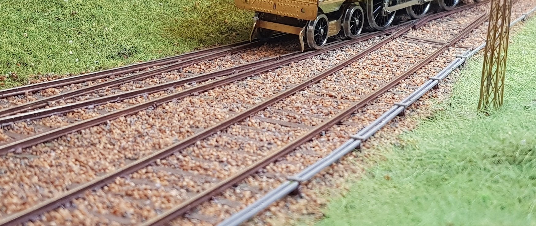
The ply an rivet method is another option not mentioned much thus far. Quite straight forward and plenty of supplies from Scalefour shop. Sleeper lenghts are scaled 9" with pre-drilled holes for rivets. Have to confess, adding the rivets can be a bit of a pain but once done track laying progress rather quickly. There are no pre-made sleepering for 21mm points, so you have to cut & drill your own sleepers which does take a little time, however you do get to build your own points in a more protobypical way as @RichL noted above. Accessories for this system do make building a little easier. Sleepers & rivets top & left. Rail droppers bottom are used to provide power to the track. The rivet goes throug the eylet & through the sleeper which means electrical connections are kept very low and are not soldered to the rail. The brass fittings are designed for points to support the switchrail - they slip over the rivet & track is soldered over them, a la below. Track power connections using the rail droppers are just visilbe 4th full sleeper in from the left. I have become a fan of the rivet method as the rivet does lift the track up off the sleeper giving the illusion of a chair. It's just an illusion, but as per the 2ft rule, it look fine. Some people go for splitting plastic chairs and fitting them either side of the rail which sounds simple, but a lot of the chair needs to be removed to avoid the rivet. Tried it - life is just too short for that!!. I'm sure all track building methods have their pros & cons, however they do have one thing in common - it takes time. I find you get a lot quicker with practice, however I did get the jigs for filing vees & switch rails which did improve accuracy. One bit I do find tricky, (and there's not a lot of information out there) is switchblade stretchers and ensuring the switch rail sets firmly to the stock rail. Any tips on this element would be most appreciated. Ken.
-
Shortest train utilising Cravens snack car?
KMCE replied to murphaph's question in Questions & Answers
Of course - Jaysus, you think I would get it right after that amount of time on the train!!!!!! -
Shortest train utilising Cravens snack car?
KMCE replied to murphaph's question in Questions & Answers
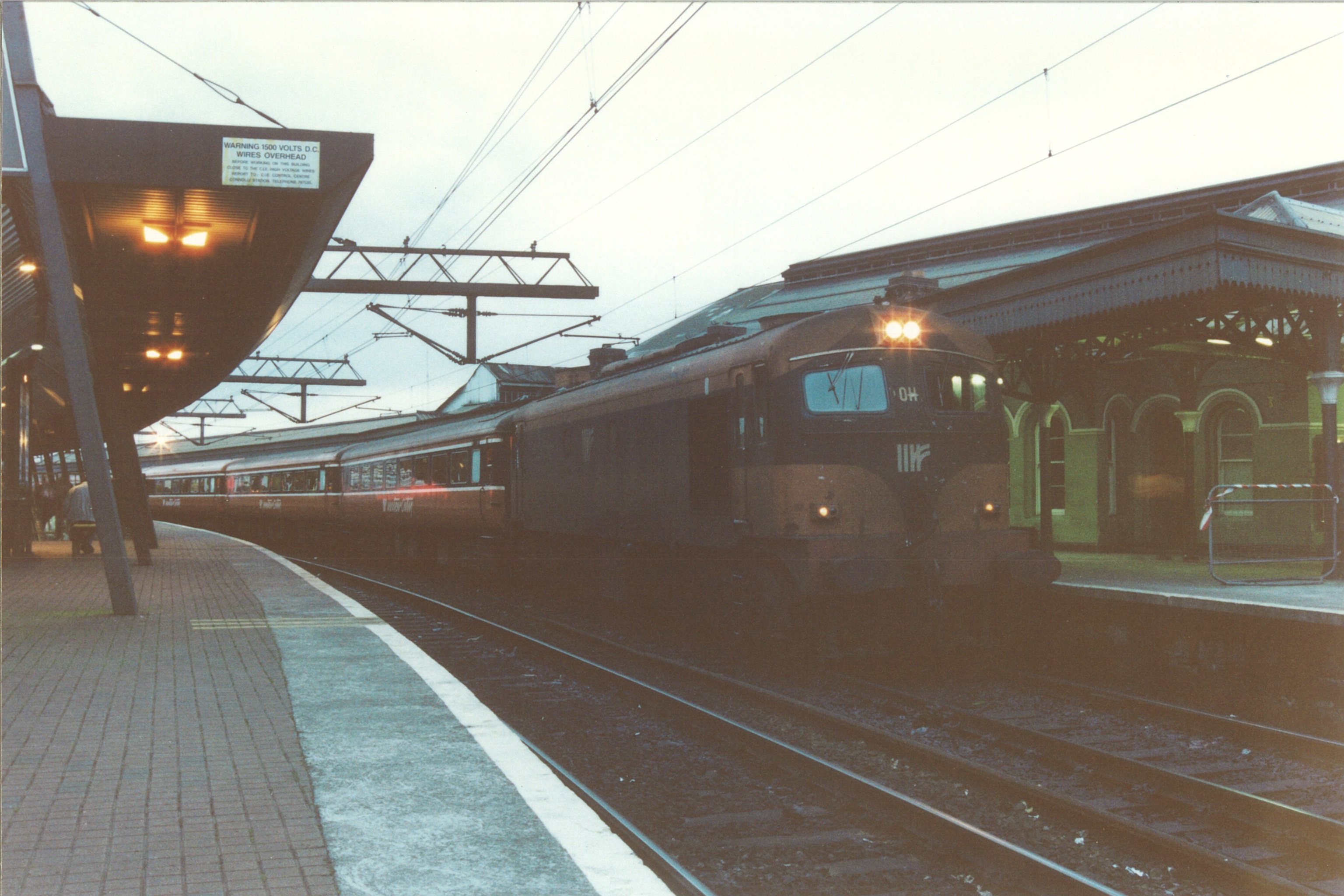
This one I recognise. That's the 17:25 to Arklow on Platform 5 - Huston. I travelled on that train for 4-5 years (c. 1988), which normally consisted of 4-5 coaches with a generating van - there was never a snack car on this one as it was commuter only. This one would have been the Dublin Rosslare train aroun the same time (again platform 5 - 18:30) which always included a snack car - not always open however. Not sure how useful this is, however it did bring back some memories!! Ken
-
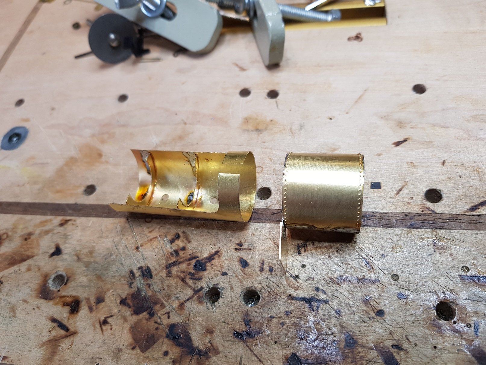
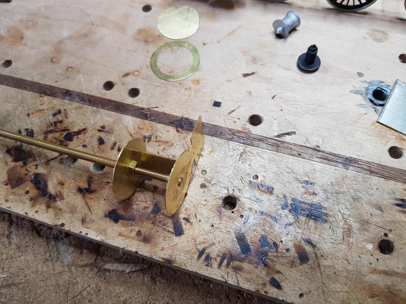
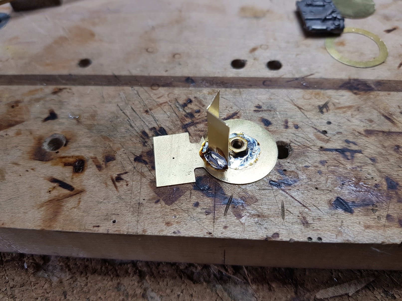
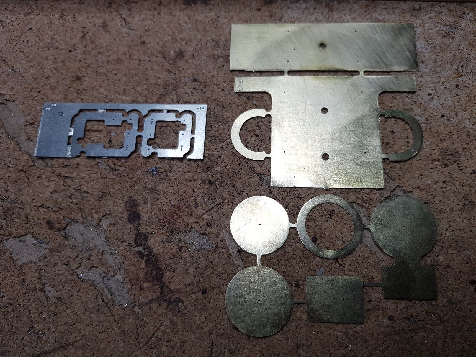
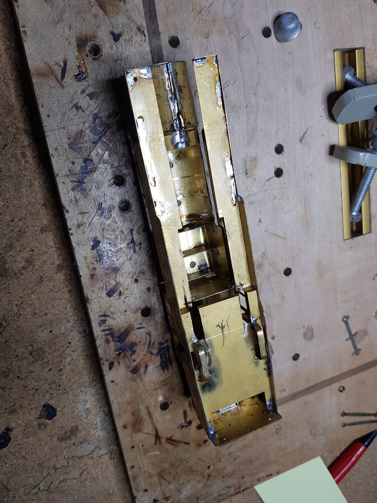
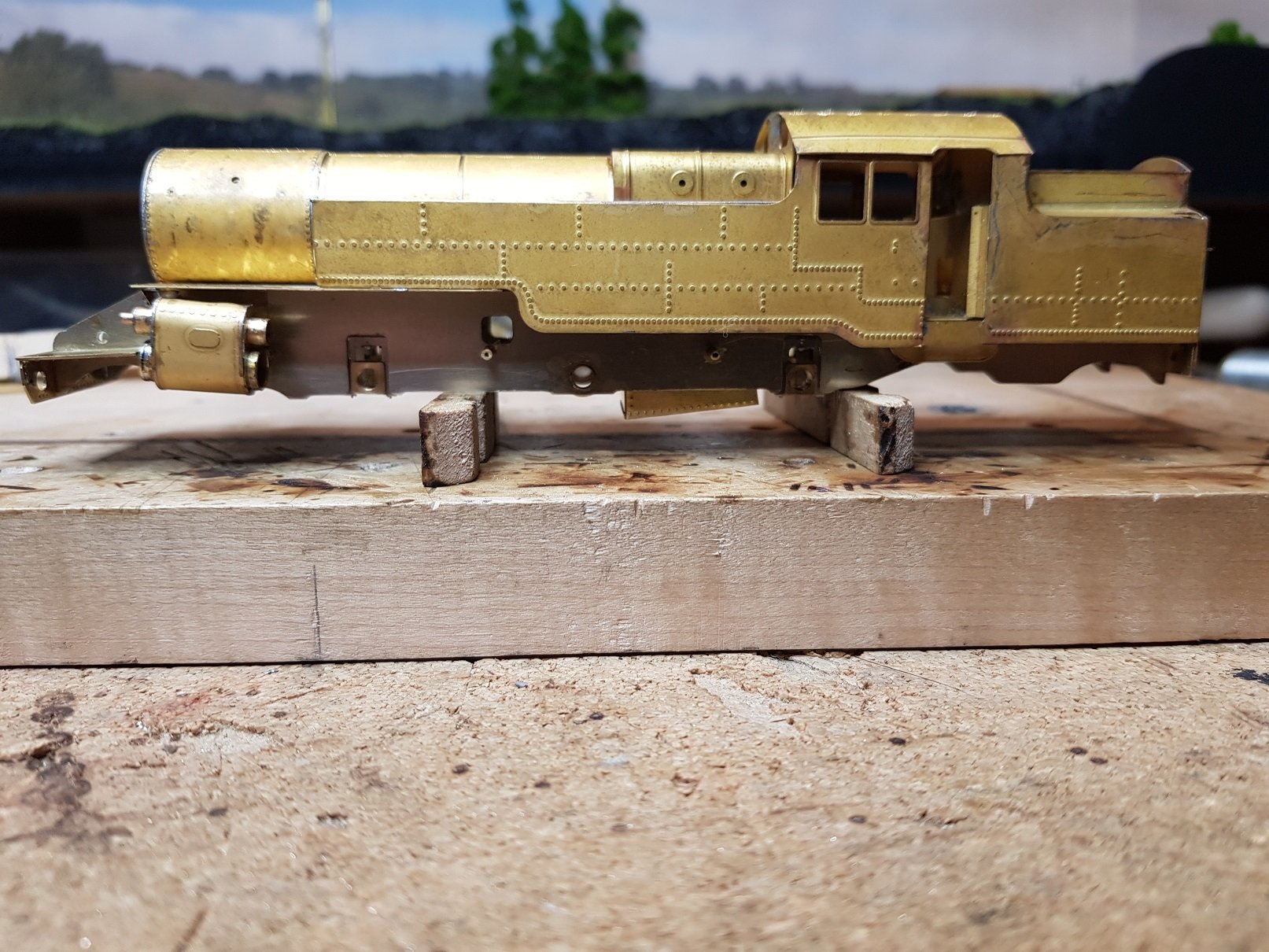
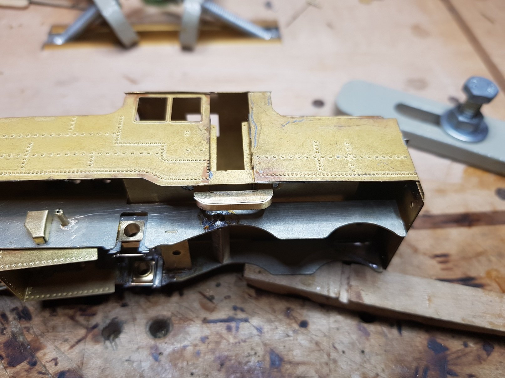
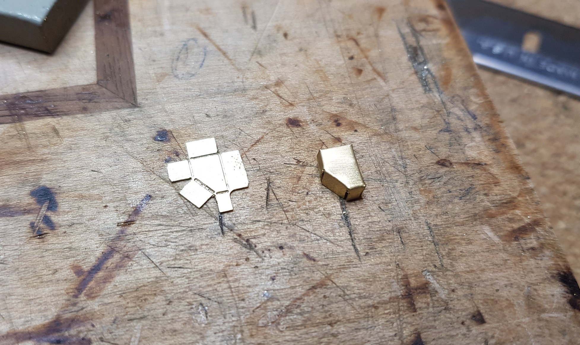
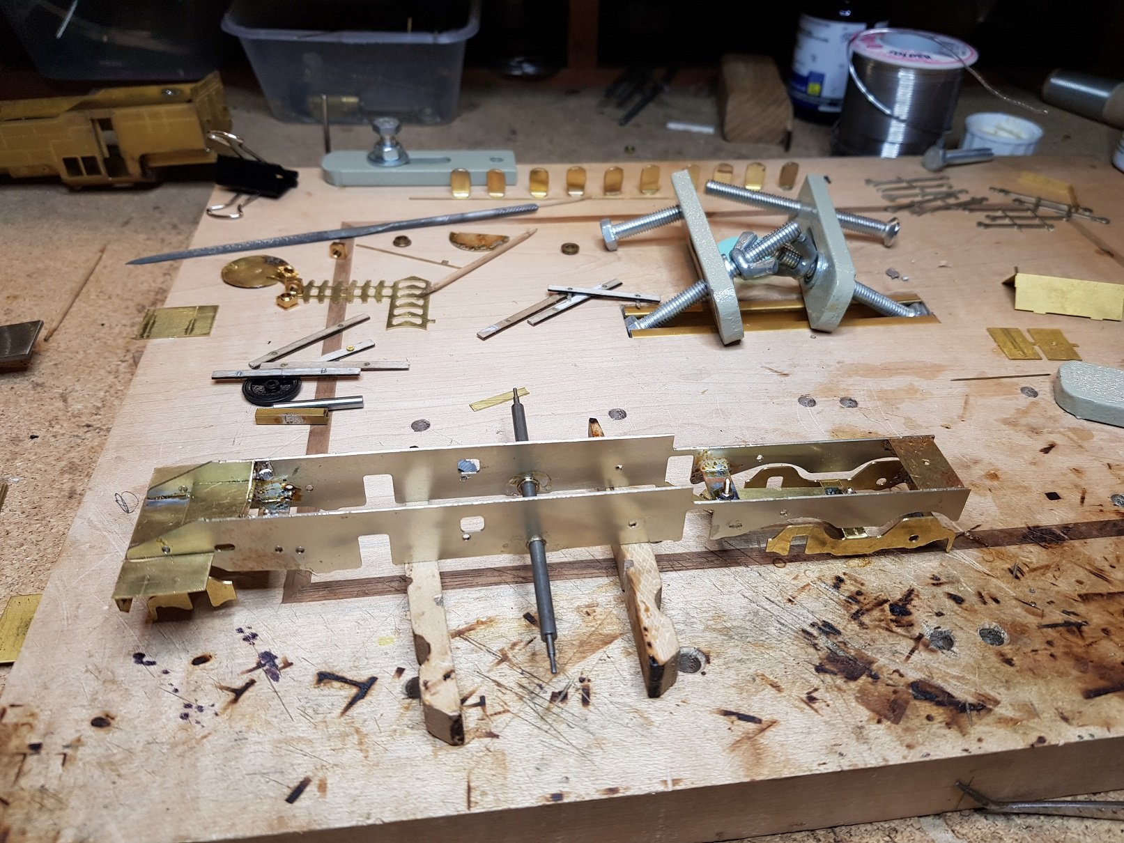
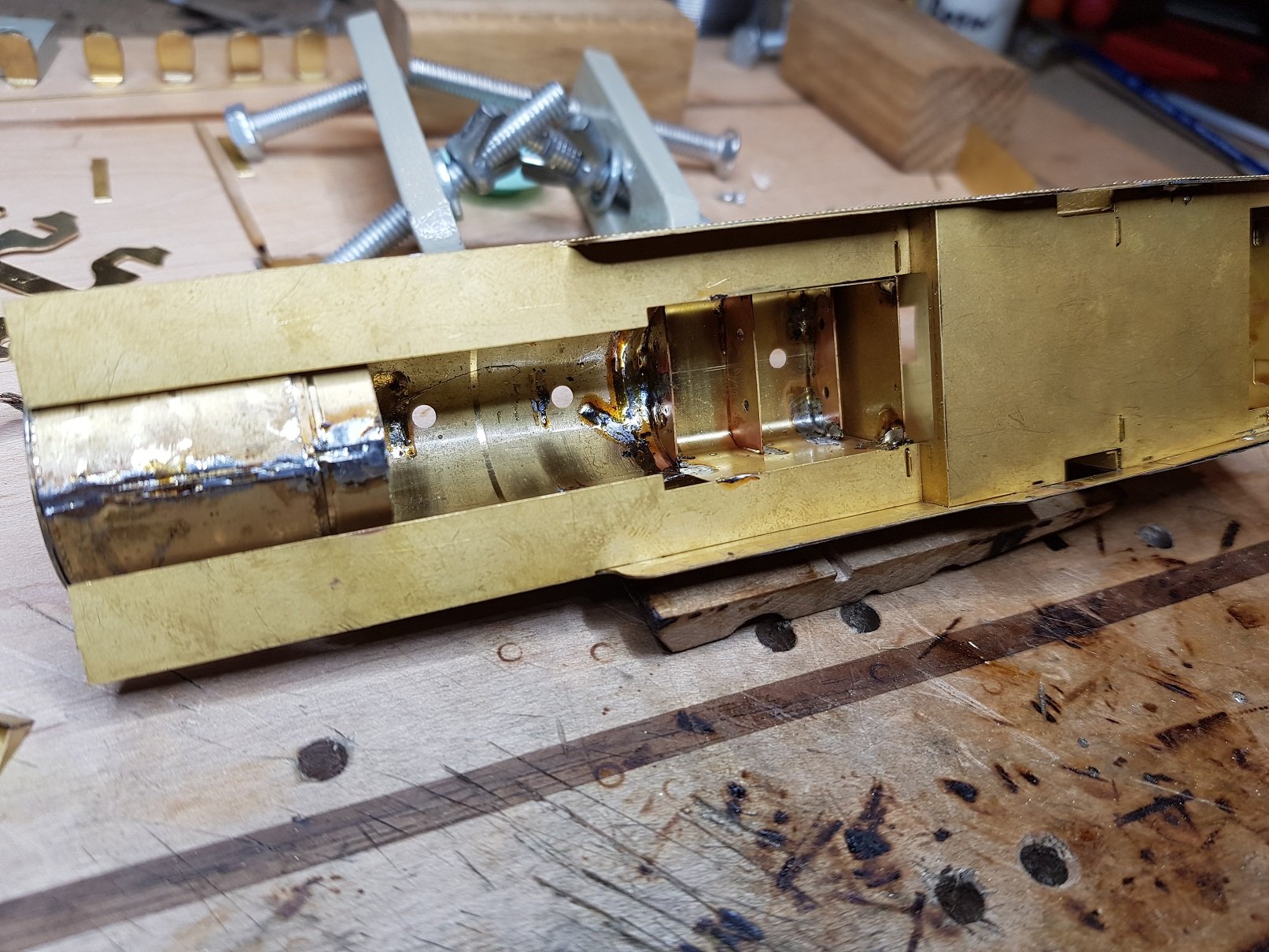
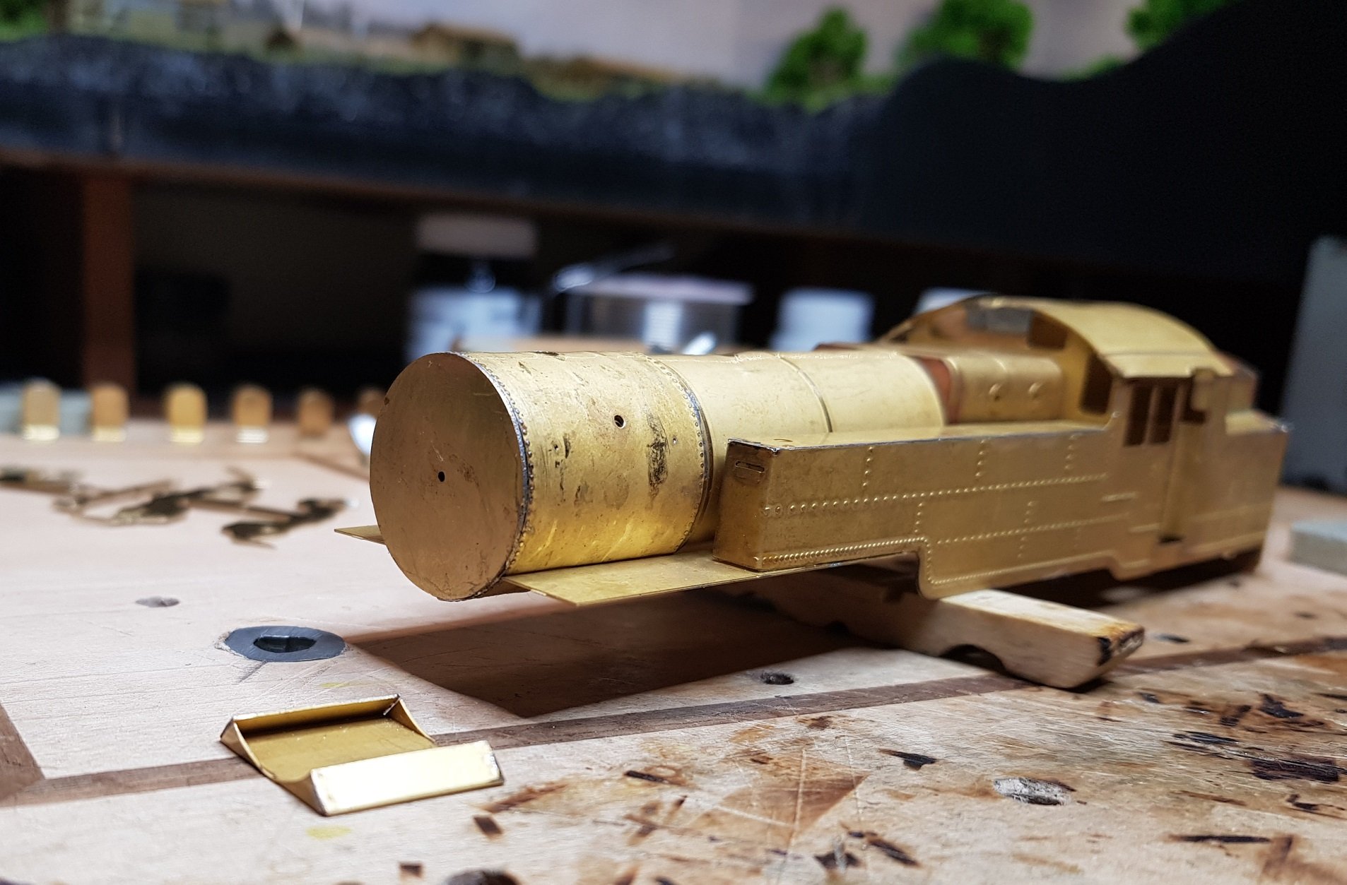
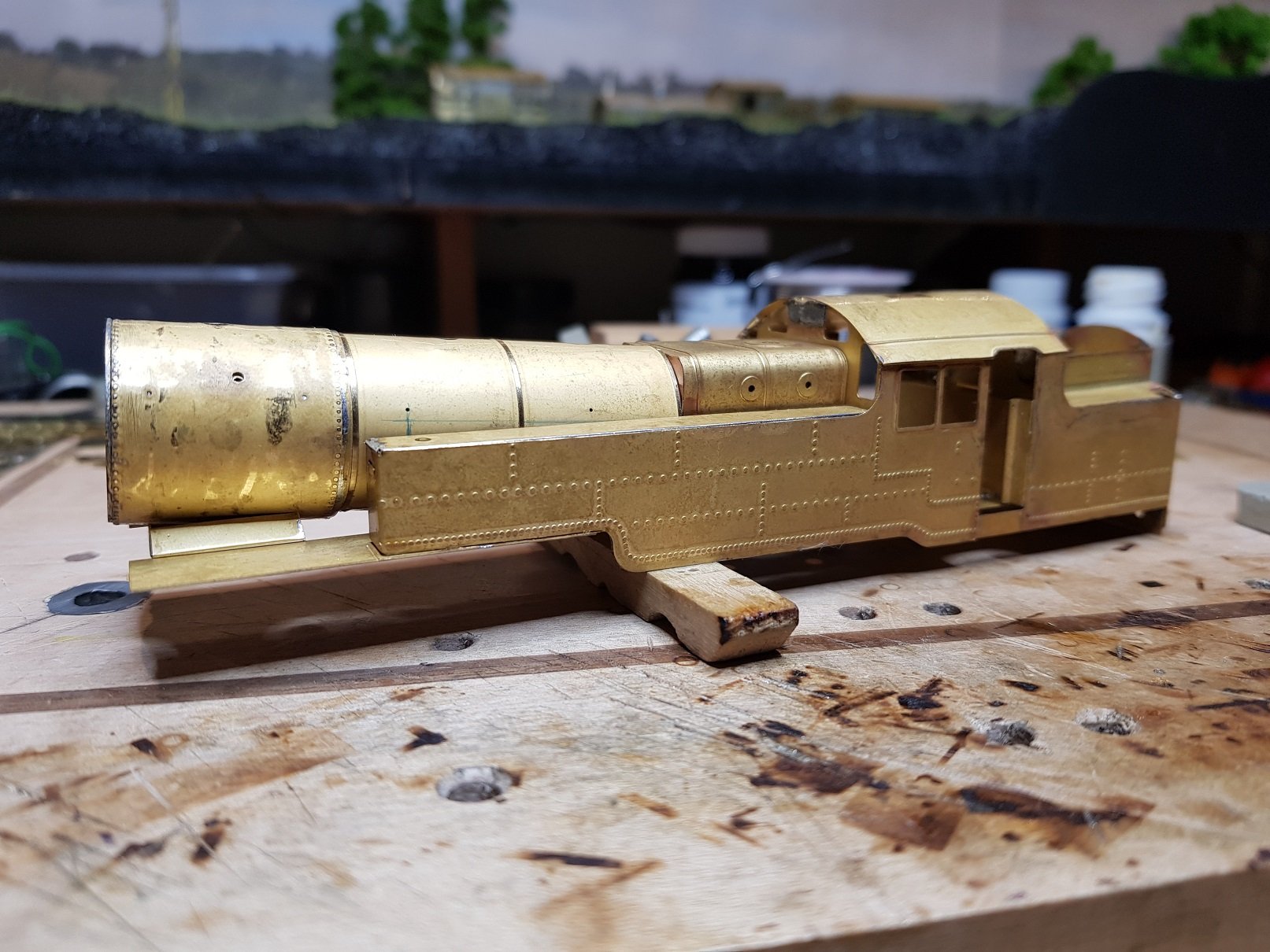
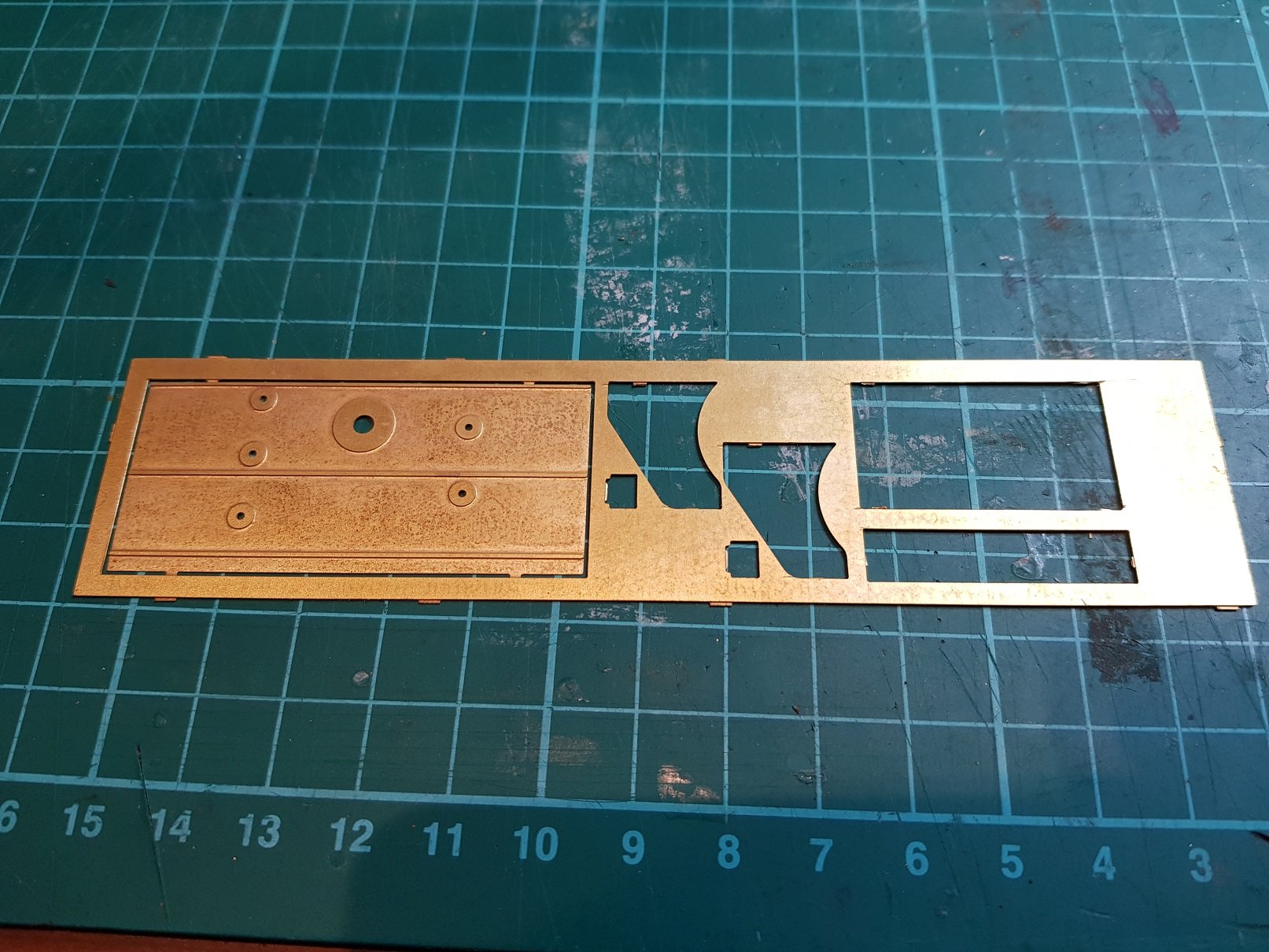
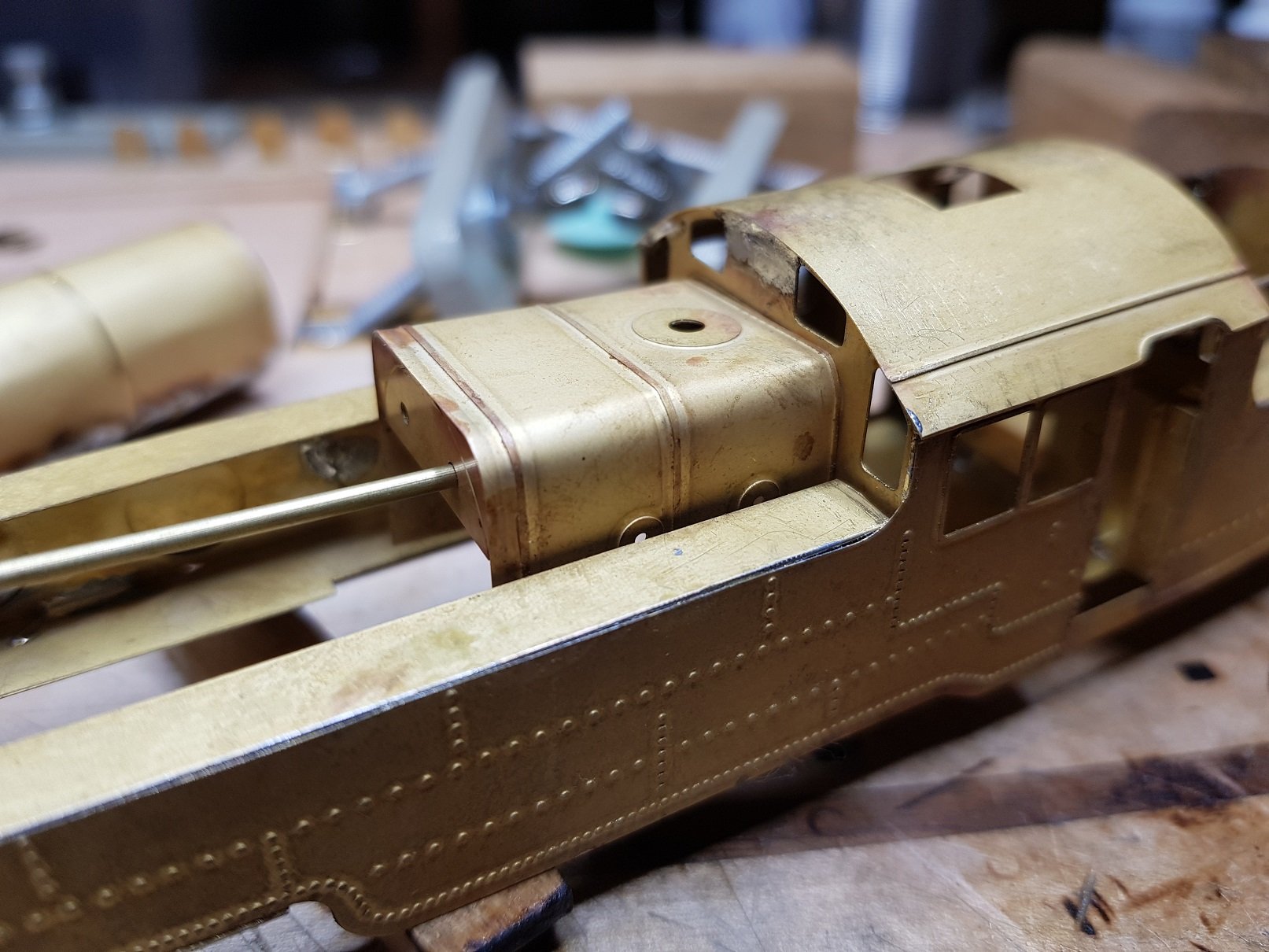
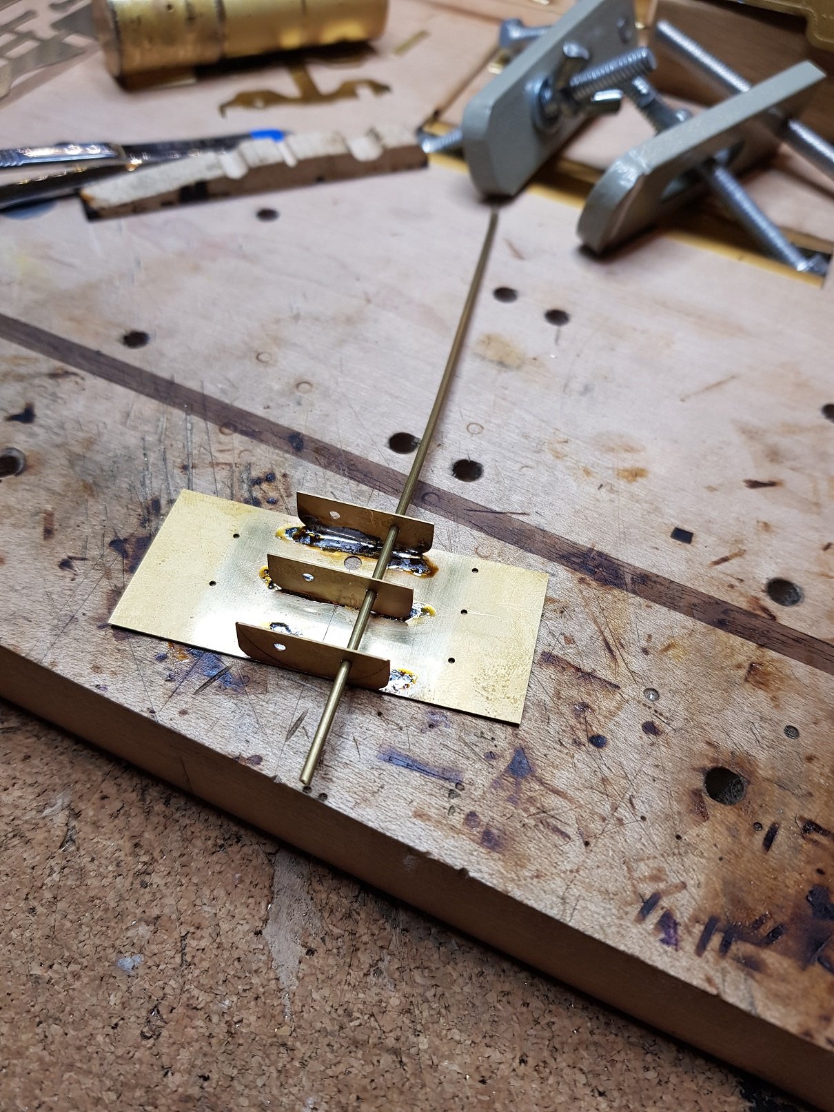
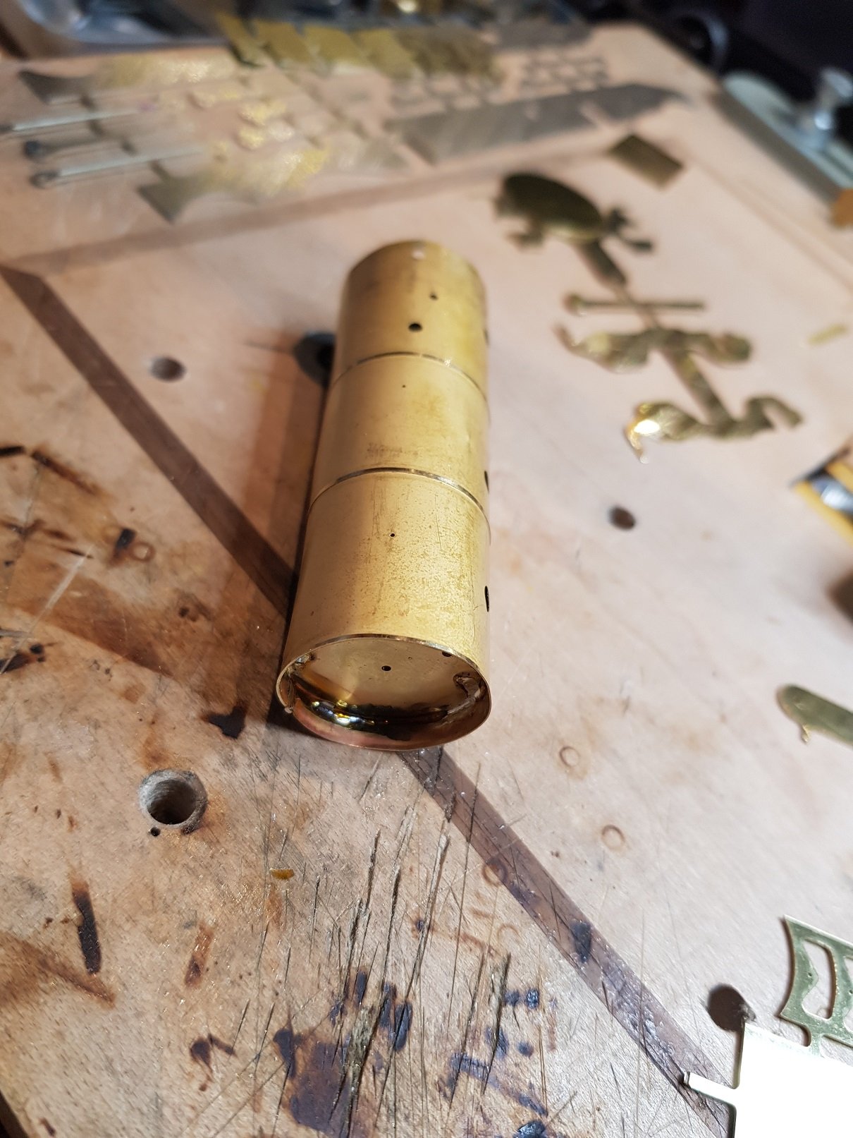
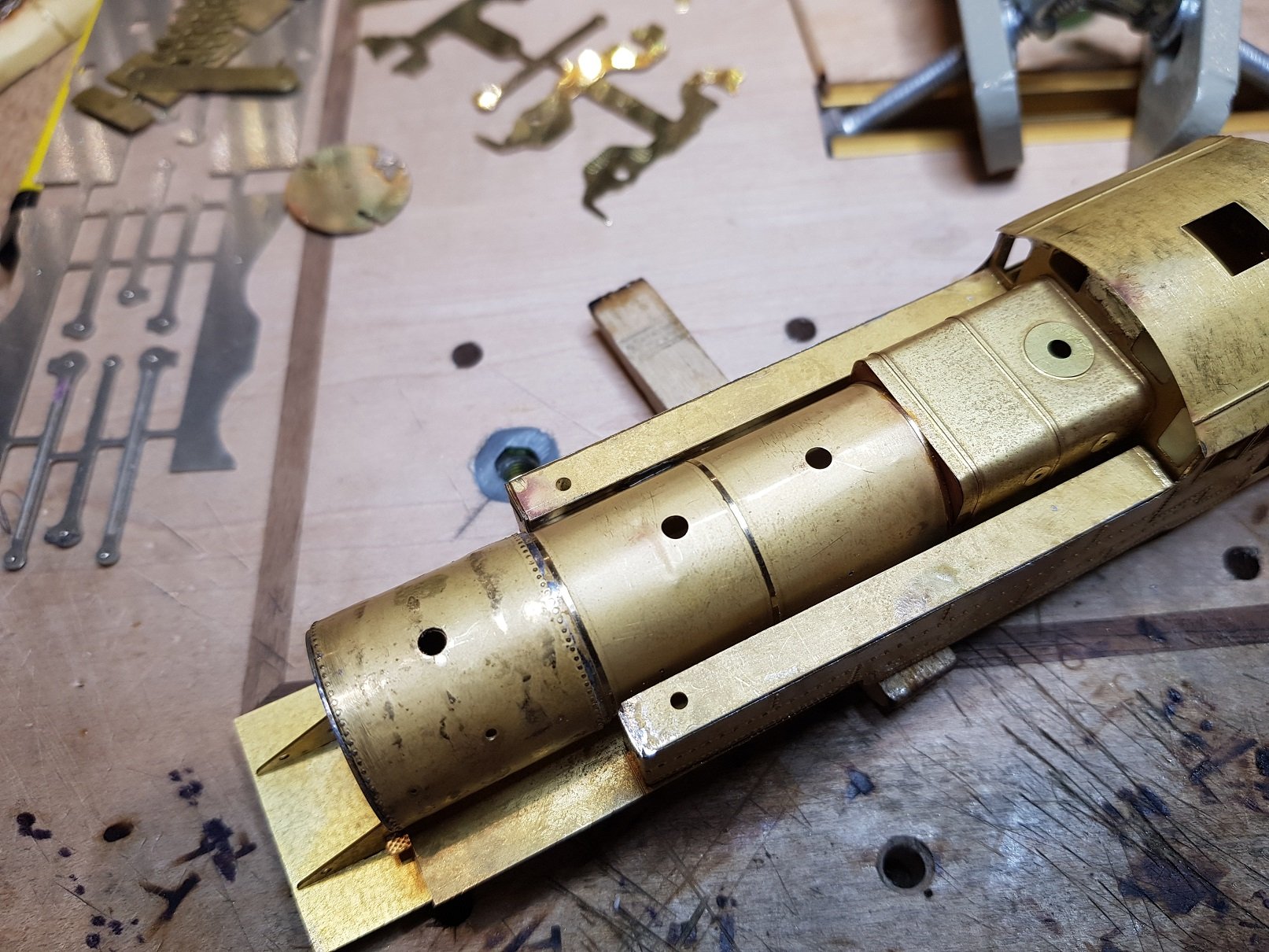
So, in a case of one step forward, two steps back, I needed to revisit the boiler and smokebox. The original etches provided a long boiler with two layers laminated over it to create the smokebox. This created a number of problems for me, one the layers started to delaminate as I was working, so figured the level of heat required to ensure three layers were complely and securely fixed was more that my iron could comfortably provide, two, the smoke box was too far forward on the chassis. A third problem was the thin nature of the boiler etch which took some damage when I was cutting out the slot for the motor. So back to the drawing board and my preferred method for making boiler & smokeboxs - former and wrapper for smoke box bolted to a separate boiler. New parts cut for fresh boiler and shortened smokebox: Nickle silver parts were created for the valve gear support (more later) Smoke box backplate with boiler fixing nut and spacer added. Threaded rod & nuts allows lining up of the rest of the smoke box former. Circle of brass above the former is the front space and carrier for the smokebox door. New smokebox wrapper was rivetted, wrapped around the former and soldered. Boiler was wrapped around the semi circular formers with the full circle added to the front to allow bolting to the smokebox. All assembled and added to the firebox and fixed back into the body. This revised design allowed for a version of the smokebox saddle to be added which fixed those fiddly footplate elements and strenghtened up the front of the body. All good then ..............sadly no. The smokebox just looked too short. A distinctive feature of these locomotives is the large smokebox and this was just a tad too short. Given the construction, it was easy to make a new wrapper and redo the smokebox, and now we get this: Another element I wanted to sort was the positioning of the cylinders - they were a little too far forward, so some tweaking to the supports moved them back slightly which now look more prototypical. Now with a much stronger front end, and things looking more prototypical, I can move on to adding steam pipes, detailing parts and get started on the valve gear. All for now, more as time permits. Ken
-
Ernies Massive Irish 1930's to 2005 Photo Archive
KMCE replied to Glenderg's topic in Photos & Videos of the Prototype
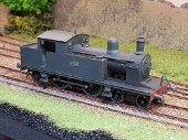
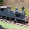
Great shot looking down on 56. This will provide some really good information on details on the top of the tanks for my WT build. Thanks for posting. Ken -
Now that looks proper. Nothing like the feeling of getting a chassis rolling for the first time. Best of luck with it - long way to go but the journey is rather enjoyable. Ken
-
Sounds like a serious make over in progress. I'm sure you'll find all those things you bought for models ages ago and forgot about. I know every time I do a serious tidy up, or deep search for some parts, there is always an "oh look what i found", then promptly forget what I was looking for. Good luck with it.
-
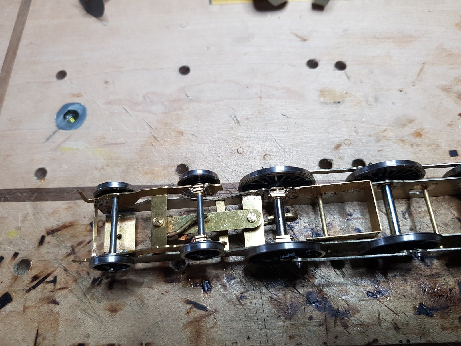
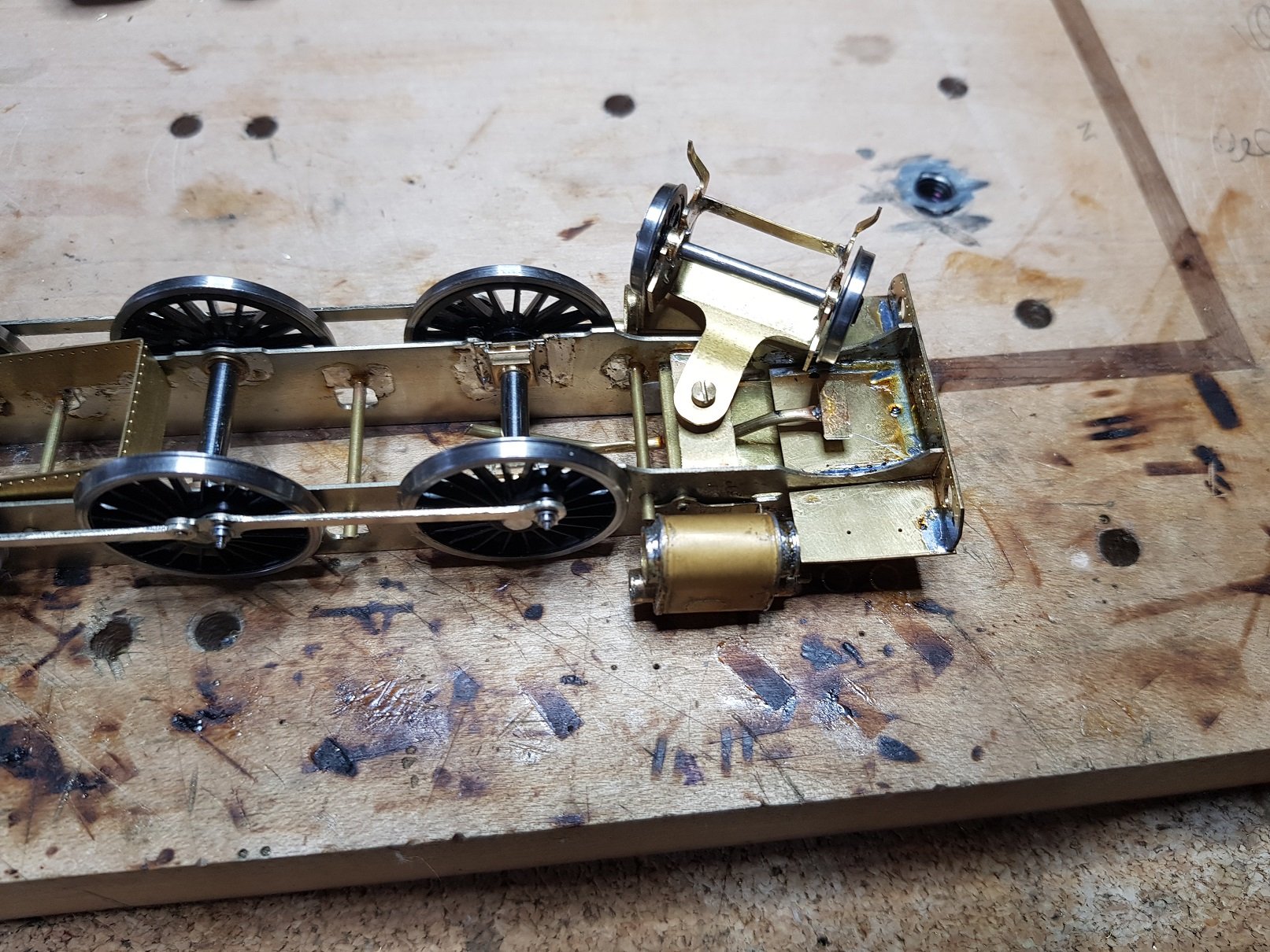
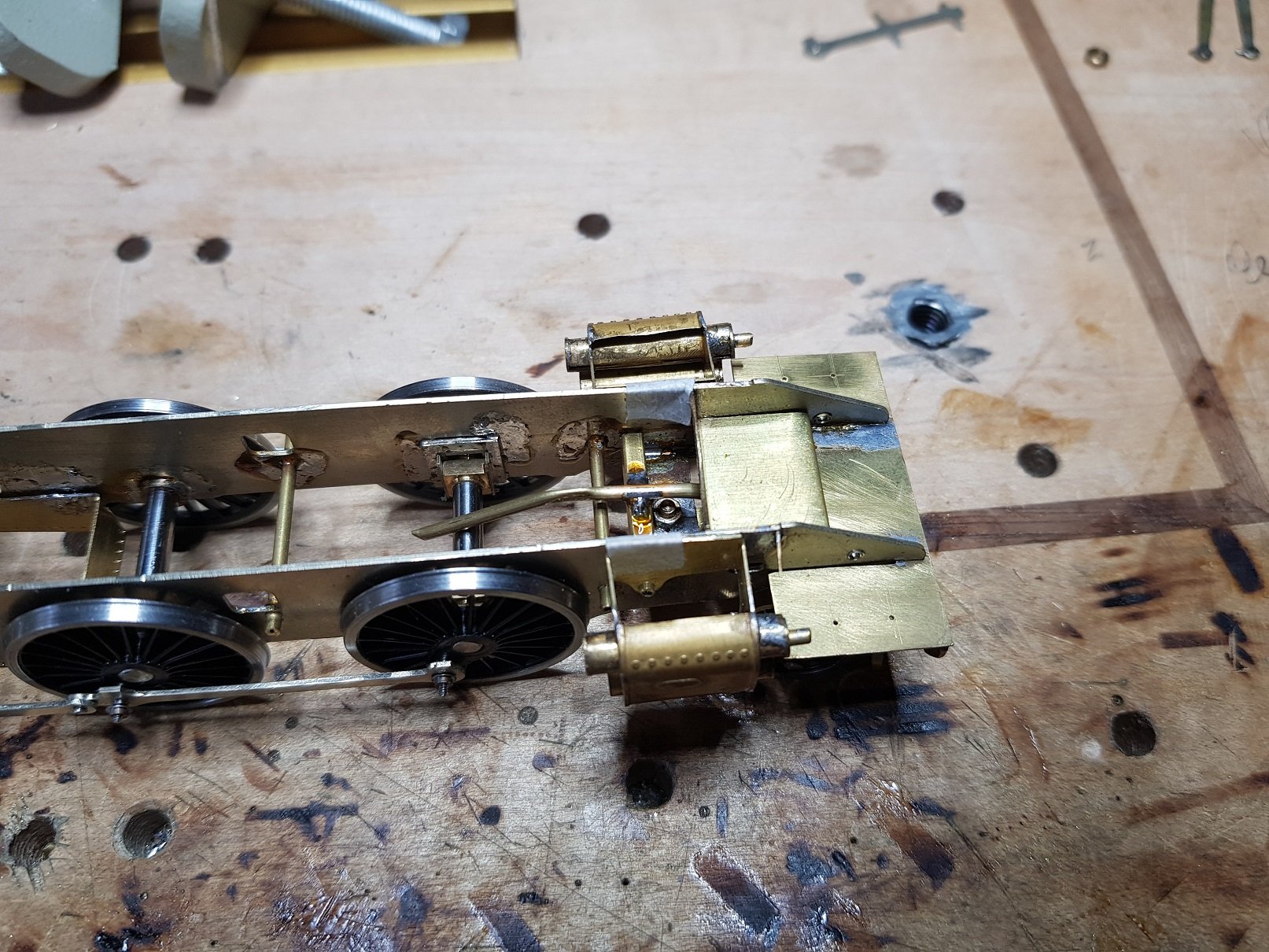
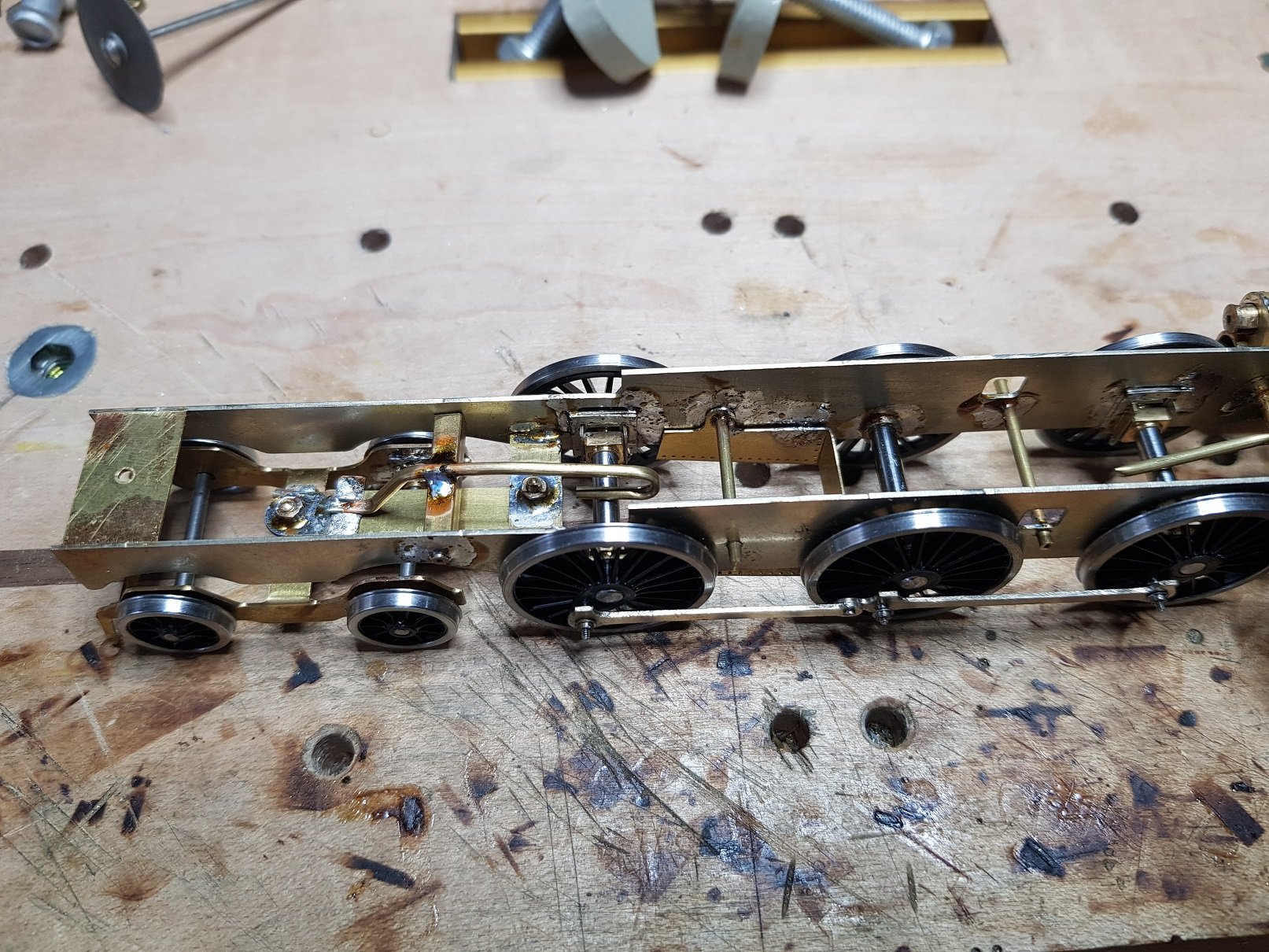
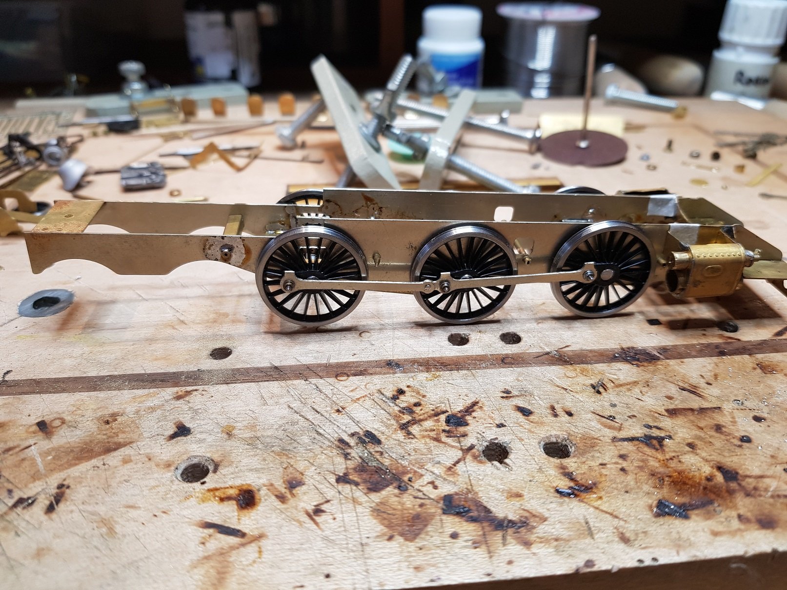
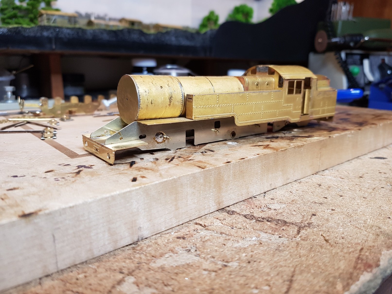
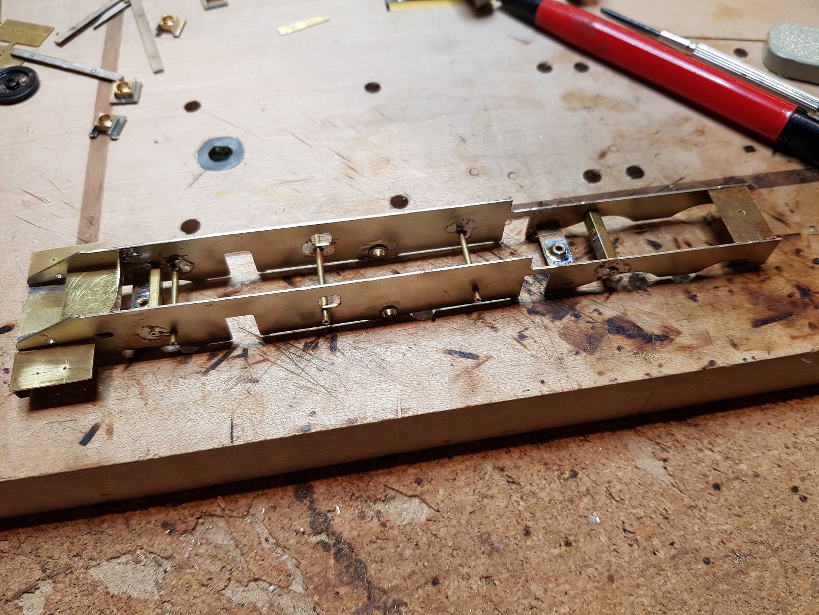
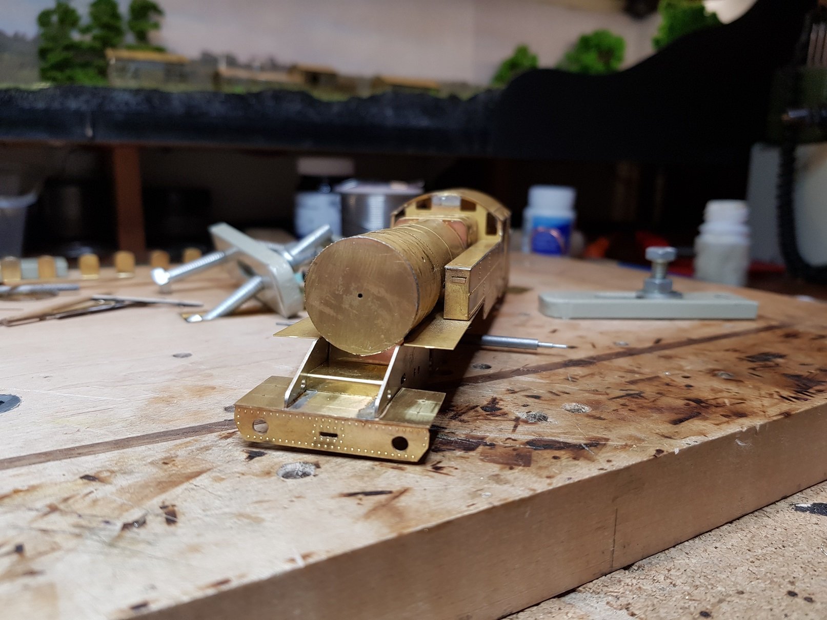
A shippment this week from Alan Gibson allowed me to get some wheels onto the chassis. As with other chassis, this one is compensated with only three fixed axles out of 6 - centre driver, for the motor & gears, leading bogie and trailing axle of the rear bogie. Coupling rods were also articulated to allow movement across the driving axles which can be seen here: Chassis is a little nose heavy in this configuration, but this will be sorted once all weight goes on. With the body added, it gets tail heavy, so bogies are necessary to level things out. Leading bogie was to have hornblocks, but given the articulation around the fixing point, I figured it was unnecessary, so solered in some 2mm chassis bearings instead. The front bogie is compensated with the leading driver, which was a bit tricky given the chassis construction and front foot plate. If I was doing this again, I think I would re-design the front compensation to make it eaiser to fit. This shot also shows how the cylinder wrapper does not completely cover the cylinder housing. A bearing pad was added to the front of the compensation rod to allow the bogie to move. A bit of PB wire will be needed to encourage the bogie to stay in line with the chassis, however it does seem to perform reasonably well as is, given the distribution of weight between driver & bogie. Next up was the rear bogie. This one has a fixed axle at the trailing end - I was looking for some stability when operating bunker first, so compensation was added to the second axle. This axle is held with hornblocks and a compensation bar fixed to the bogie cross beam - the bar was offset to allow the bolt for fixing to the trailing arm. The bogie was then compensated with the rear driving axle using 1.5mm tube and bent to shape. Again a bearing pad is used on the bogie trailing arm to allow for movement. This bogie will definitely need some wire to guide it as it is quite free to move around. OK so now we have a rolling chassis, albiet with some minor binding between the coupling rods and centre axle hub - some shims on the crankpin should sort that out. As mentioned in a post above, the rear wheels impact on the cab, and a cutout was needed to accommodate this - quite a deep cutout it transpired. This allowed the body to go on and after much tweaking of the front and rear compensation to get the body level, we now have some semblance of a locomotive. Boiler was removed to add the inner tank linings and a trim was added to the underside of the front upper footplate to match prototype. As noted above these footplate elements were quite flimsy and this trim helps to strengthen them. A quick shot with some wagons to get a indication of the size - this is a big locomotive! Cast parts are just sitting in place for the photos, and boiler has not been fixed back in place, hence the gaps Thats all for now. Ken
- 41 replies
-
- 11
-
-
-
Very nice indeed - proper quality!
-
Many thanks Eoin, I will bring them along, and will also bring the DSER Armoured train as well - it's nearing completion & still unpainted, but I'm sure it will be grand. Ken
-
"The lady doth protest to much, me thinks" Your model is fantastic, and better yet finished. You're not giving youself due credit for a excellently appointed locomotive!! Ken
-
Fantasitc paintwork Eoin. I also like the finish - its bright without being too glosssy. More power to your elbow! Ken
-
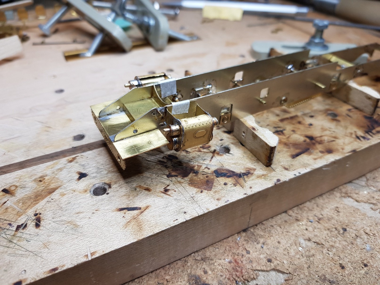
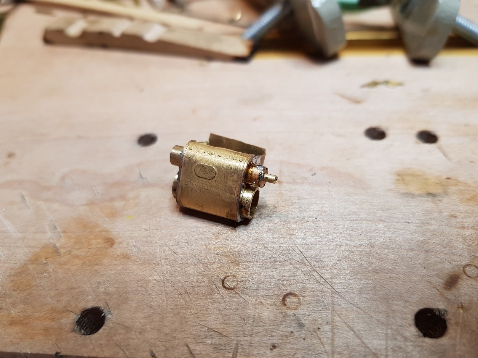
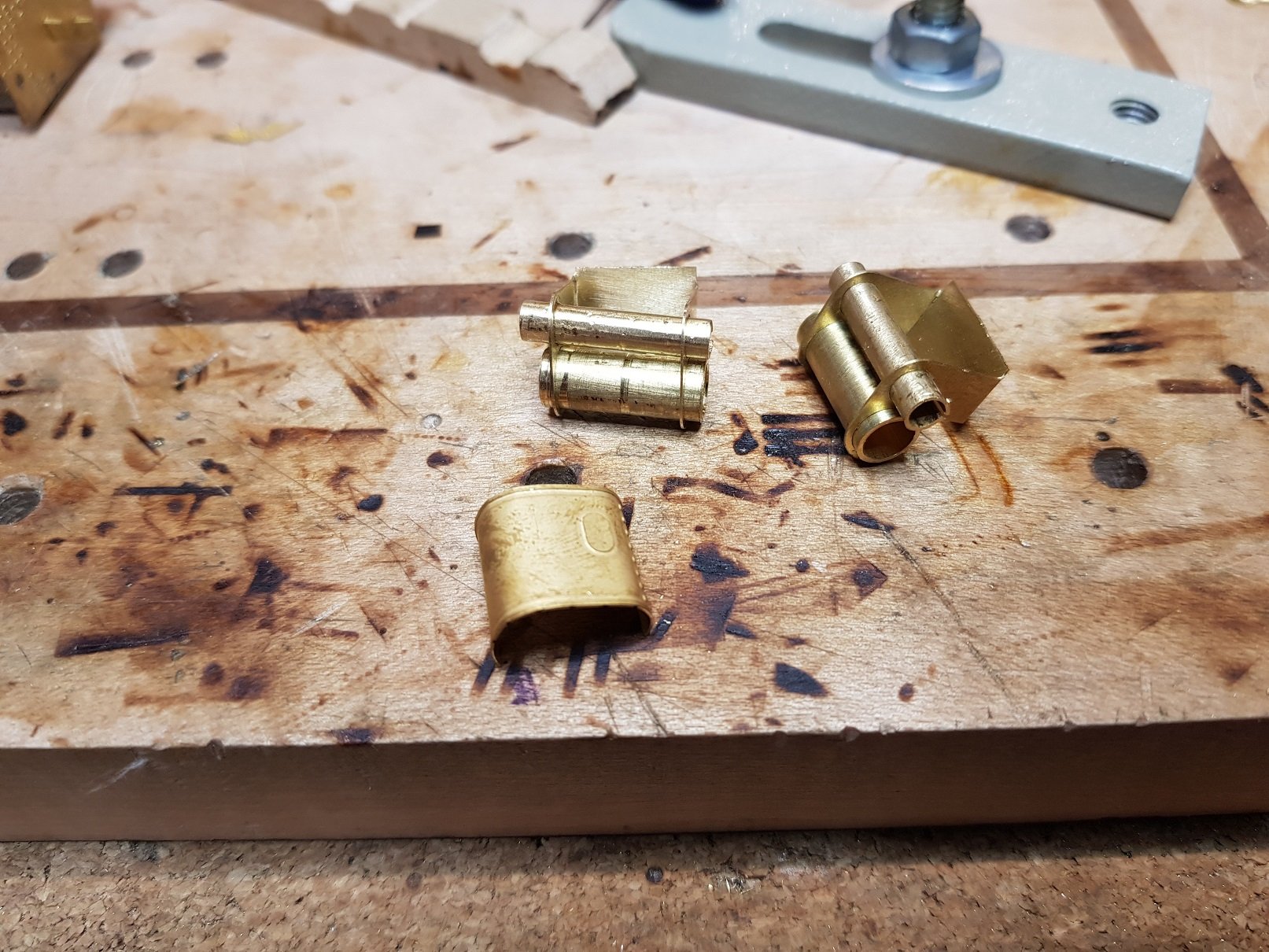
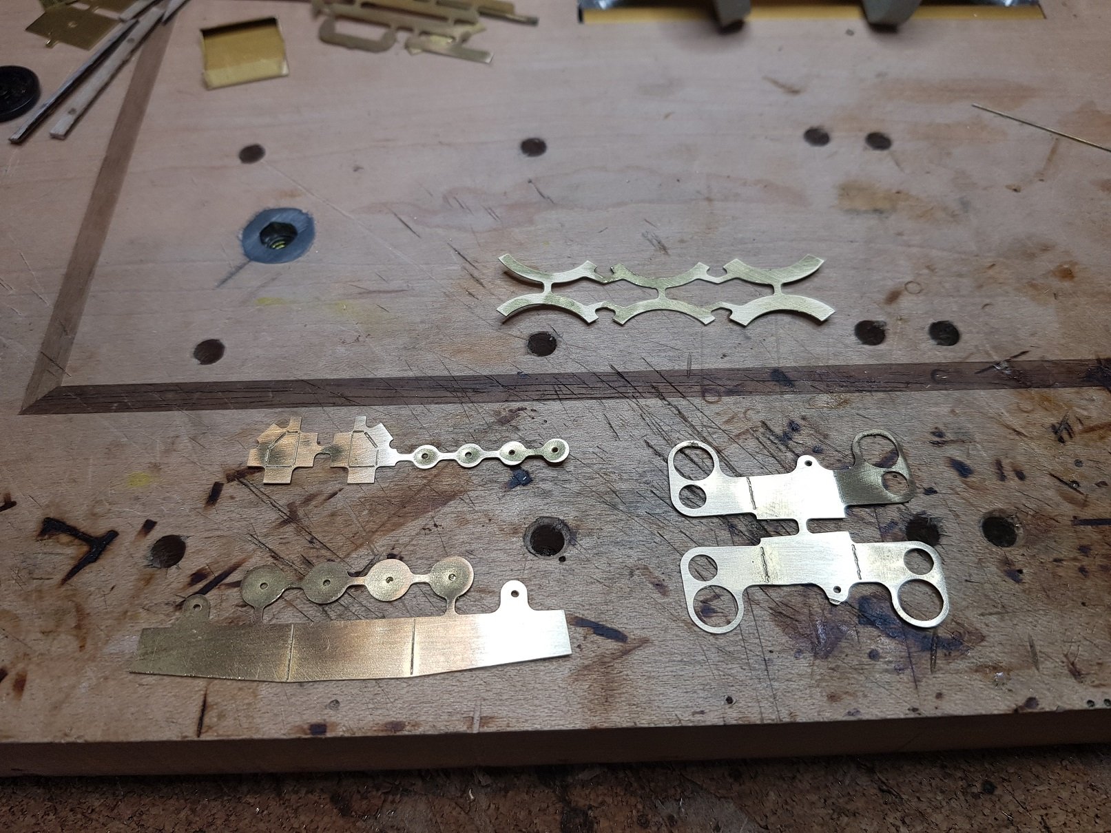
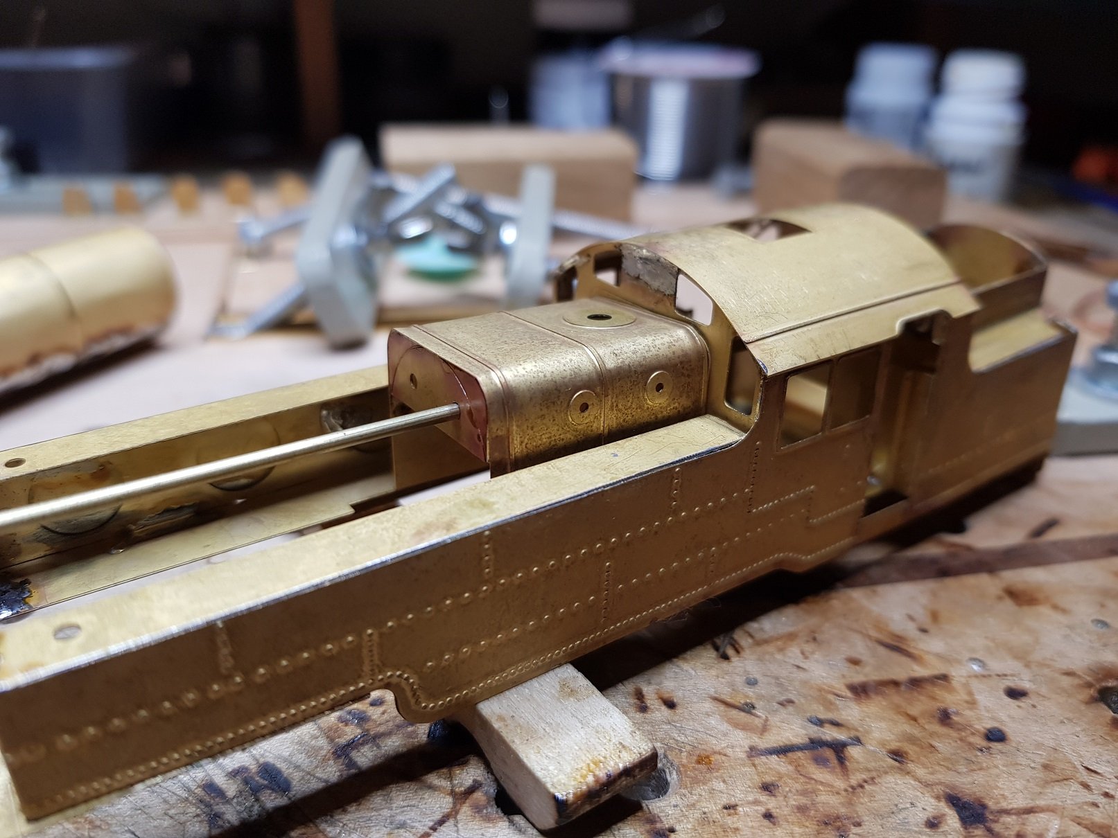
So, further progress. There is quite amount of detail visible on the prototype which led me to develop some more detailing parts. The original drawing was used to develop parts which were then cut out with the mill. This included cylinder block, sand boxes, firebox, wheel counterweights, and missing from the photo, tank connection pipe boxes located under the cab. The sandbox were trimmed and folded up into shape. Fill pipe and sand pipe will be added afterwards once I can get them set on the chassis. I propose to leave these until wheels and brakes are on to be sure a correct and non interference fit. Tank connection pipe was next up which went together well and fits in rather nicely. This is added to the footplate rather than the chassis so they line up with the tanks. Next up was cylinder construction. Cut parts and pipes form the basis of the cylinder block - the wrapper is used from the Worsley Works kit. This took a bit of headscratching, as the wrapper is quite a bit shorter than the cylinder block, so with judicious use of photos to line up the plaque, it was possible to shape the wrapper to cover the cylinders even though the top is still exposed. With the body on, this is not visible, so I'll go with it for now. The etch does look good and finishes the cylinder block rather well. Cylinder blocks were temporarily added to the chassis to see how it fits. Triangular suports were added to the chassis to suport the front of the upper footplate - fiddly little buggers, but they should provide more support, and help to close the front end. Well, you just got to put the body on & see how it looks. This last photo shows the firebox detail and also the hornblocks for front and rear drivers. Starting to take shape. More as time permits. Ken
-
That is a really nice kit and a good looking H - van. By 'eck, you are really turning out the work at the moment - all high quality as always. Ken
-
Guys, Many thanks for the comments. DH - One of these beasts is enough for now - chassis is coming along well but is taking some time to get right. More to follow. AF - I don't have that article but will try and get a look at it - Luckily there are quite a number of photos of the locos avaialbe on line which is helping considerably with the build. MM - Layout is my shelf / test track, Wicklow South - it makes an occasional outing to Bray to stretch its legs!!
-
Very nice David, and I like the subtle weathering. Just enough to take away the shiney look, but clean enough for a crew to be proud of it. Bravo!!
-
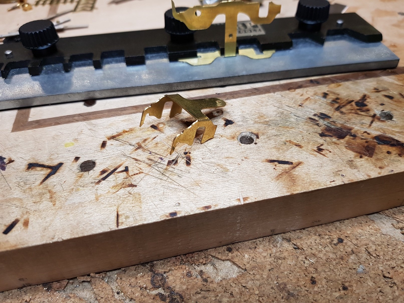
Thanks for the comments, guys - they are much appreciated. OK - Moving on. Looking at the reminaing fretwork, the kit is generally complete at this point. There are some parts left for steps, lamp irons, cylinder wrappers and a roof hatch cover, but that's pretty much it. In terms of a build, it generally is a good kit, parts fitted very well, with the odd exception as noted above. Detail is good, and I particularly like the tapering of the bunker from the cab area - doesn't really come out well in photos, but is quite pronounced from above. As can be seen, there is a long way to go before you will have a model, so some more work is needed. Chassis - From the drawing I had, I developed a chassis, spacers, brakes & hangars, pony & trailing bogies, plus the replacement parts for the front footplate. It was necesary to make a new buffer to fit the wider footplate, so that was done and rivet detail added. The other that needed to be changed is the kit does not reflect the sliding coupling hook slot; it has a basic vertical slot for a fixed coupling hook. This was addressed in the revised buffer beam. A suport for the boiler, which closes in the front of the frames was also made up and added which helps to build up the font foot plate area. Steps and and triangular wing pieces needed for the front of the upper footplate. I need to stablise the these foot plate elements as they are quite thin and will need suport in the final model; I may incorporate something with the wing pieces to provide stiffening. Pony and trailing bogies were next up, and they folded up quite nicely. A cross brace was added to both bogies and then they were tried with the chassis for fit. The rear bogie is a fraction too far back, but a small set in the trailing arm should both set the height & bring this back in line. Some wheels would assist here as it will prove easier to line up with the arches in the frames. As an aside, it's clear these locos were designed to operate very tight radii - arches in the chassis to allow bogie wheel movement, laterally sliding coupling hook and oval buffers. Quite a good design! Tubes for brake hangars and compensation beams were added which help to stiffen up the chassis to get ready for hornblock install. So for now, we have a body sitting on a basic chassis. More as time permits. Ken
-
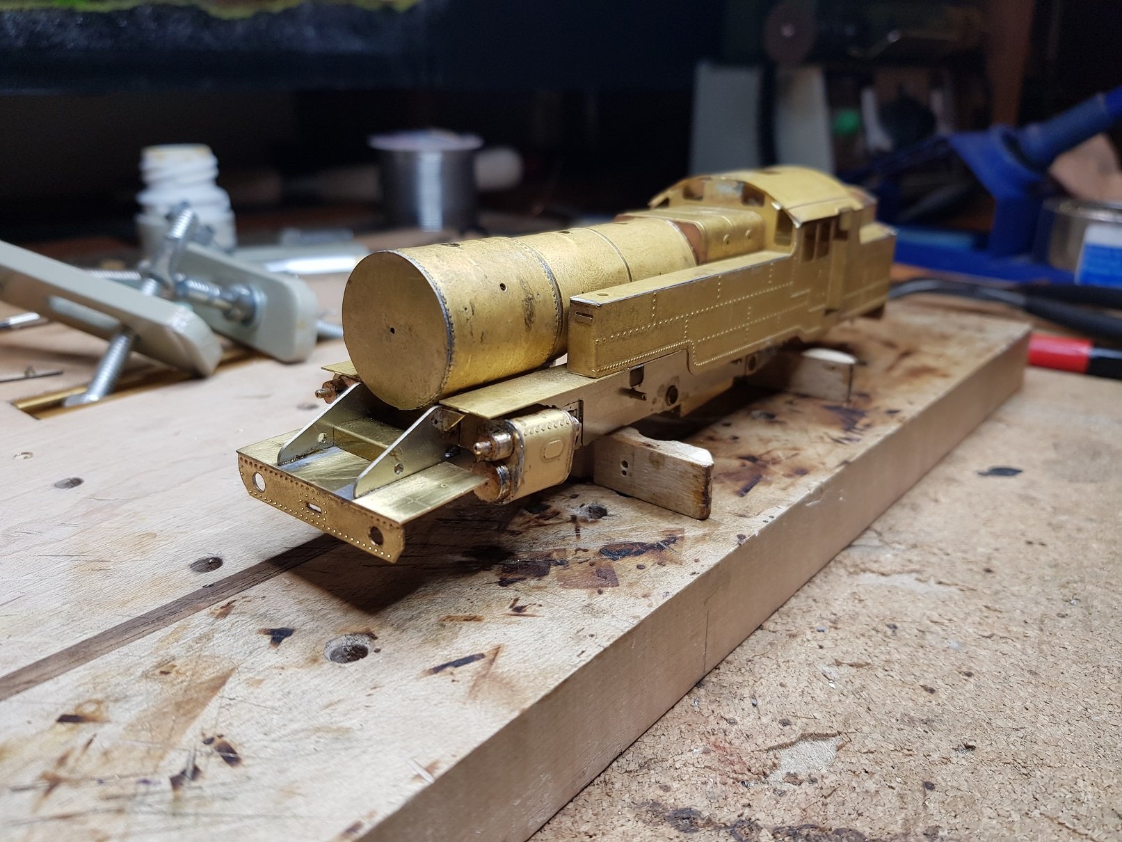
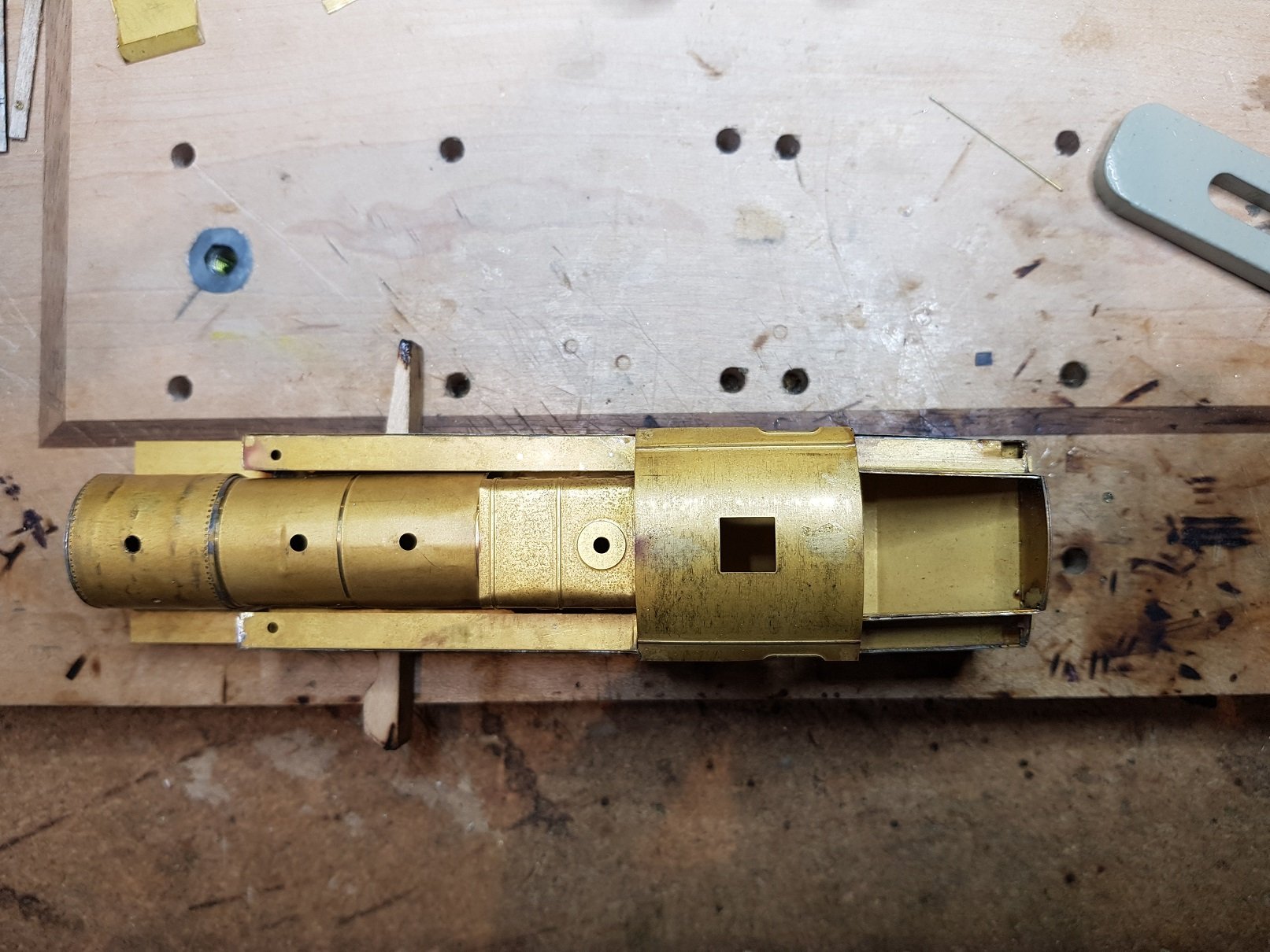
So, some progress. Initially rolled the boiler barrel and smoke box sections & while the smoke box sections were fine, the boiler barrel had a tendancy to kink where holes were included. To avoid this, I cut some discs to create form work to allow soldering. This worked well and allowed the completion of the boiler. Smokebox wrappers were attached and soldered at the bottom where they joined. I added a disc to the front of the smokebox, as there is nothing in the kit to close off the front end of the boiler. A cast smoke box door can be added later to finish this. Moving on to the firebox, the kit provides some nice formers, complete with holes to allow lining up and wrapping of the firebox. Very nice detail & allows this section to be created without too much difficulty. Alas, spoke too soon. Washout plugs are below the tank level! What I didn't note in my earlier posts, is that there is a third etch fret with the kit, much smaller which included revised (longer) front foot plate sections and a firebox wrap. Now I know why this was provided. I undid the firebox wrap to save the formers and went at it with the new etch. Much better. Now to join boiler to firebox, mount the saddle & we're done. Eh - no! Take away the saddle and let the boiler mate to the firebox, the smokebox sits below the footplate level. Quck check with a few photos of the prototype & sure enough the smokebox is below the footplate level, however there is some evidence of a saddle above the footplate, so this will need a little thnking about. Now boiler is in place a quick look around spotted another issue that will need to be resolved. Proportioning of the boiler and tanks is good which means there is space between the boiler and side tanks (as there would be), however with no internal wall to the tanks, the gap doesnt look right. A quick strip of brass will solve the issue, and thankfully the boiler is only tacked in position for the moment and will come back out quite easily. Next thing to resolve is the cutout to allow the motor sit over the chassis. I cut back the boiler to almost half circle but stopped well short of the tank sides to be sure this would not be visible from any angle, particualarly from above. This provides plenty of space for my setup as I am making my own chassis and will drive the centre axle, however it's not so good for the Hornby chassis. For those who asked about fittment to an RTR chassis, I have two versions of the Hornby chassis, older & newer, and it would require considerable cutting to the smoke box to allow either to fit; the worst being the newer chassis. Older chassis - Motor is fouling the firebox formers, but with some minor cutting this could be made fit. The higher chassis at front would need a slot cut out of the smoke box to fit. Newer chassis - motor is shorter, however much further forward. This would need a considerable cut out of the smokebox, which may be visible when the front footplate is added. I think the older chassis may be eaiser to work with if I were going that route. Moving on, The lower footplate was offered up to the chassis now that the boiler is in place, but to me it doesn't look right; front footplate and frames appear too narrow. Frames do not line up with the insides of the upper footplate, however this maybe to suit a OO chassis. Spacing of the upper footplate suits a 21mm setup. The width of the footplate seems well short of the main upper footplate. A quick check on the drawings does note a slight difference in width c. 0.75mm either side at scale level or 2 - 2.5" on the prototype. In photos of the prototype the width of both footplates appear the same, however photo angles may not allow a good view. I have allowed a new lower foot plate in my chassis design, so this will be replaced as part of the chassis development. More as time permits. Ken
-
All, thanks for the input, I have the same drawing noted above and have developed my chassis from this drawing but was looking to see if anyone had a more detailed drawing. I may press on with what I have and see how it turns out - it shouldn't be far off, as it is very difficult to see the frames in any on the photos I've seen! In the meantime, I may do some research on the book by Scott & the article in Five Foot Three. More as time permits Ken
-
Now that, sir, is a fine looking model. Well done!