KMCE
-
Posts
540 -
Joined
-
Last visited
-
Days Won
29
Content Type
Profiles
Forums
Events
Gallery
Blogs
Store
Community Map
Everything posted by KMCE
-
The 850 is on my list of locos to build. Developed the drawings & nearly cut out at kit; the mill did not cut through the sheet, so kit is sitting on a shelf. Must get back to it, as it is a very nice loco. Your secret builder moves rather quickly it has to be said! Ken
-
Don't know if this is of any use, but was posted by someone here on the forum some time ago. http://www.kwtrams.co.uk/productdisplay/kw-002j-dublin-199 Ken
-
MIke, My intention is to scratch build my own chassis. The kit is advertised to fit the Hornby chassis, however the Fowler chassis I have (old I admit) does not quite fit. I'm working with 21mm, so the Hornby chassis would not work for me anyway. Generally it fits with the excpetion of the rear drivers which catch the step in the footplate. To be fair, it does not impinge too mucth, perhaps 5mm, so with some judicial trimming into the step & cab floor, it should fit. Hope that helps. As to the chassis, having taken some measurments, I noted that there were a few discrepancies compared to the Fowler chassis. Wheel size on my fowler is 5' 6" where the prototype is 6'. Also the axle spacing is different. I have drafted up a chassis with correct spacing & adjusted for larger drivers. I was going to use the runnig gear, but it looks like I will need to make coupling & connecting rods - the rest, I may be able to use. WIth the revised spacing & wheel size, the rear drivers will impact on the cab area even more, so looks like I will be cutting into the cab floor anyway, so I may fix some of the issues noted above. While I'm here, does anyone have a drawing of a WT chassis I could use for reference? I can share the results of drawings once developed for the model. Ken

-
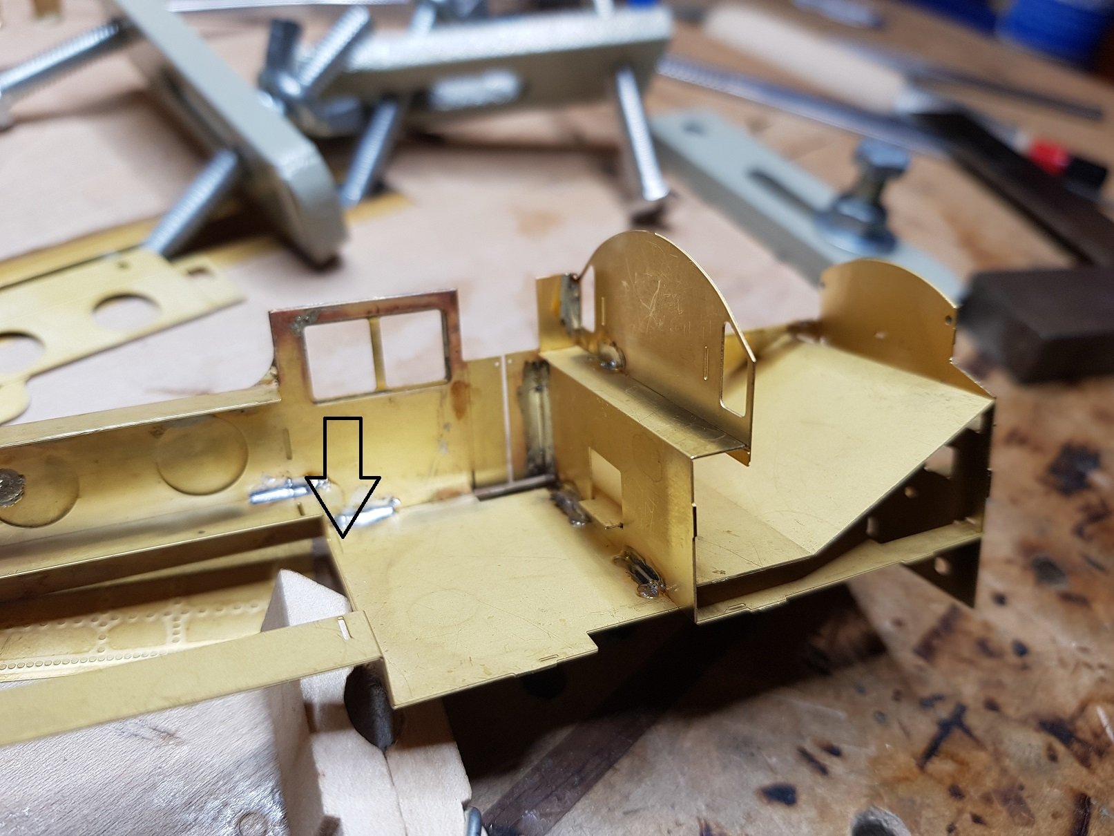
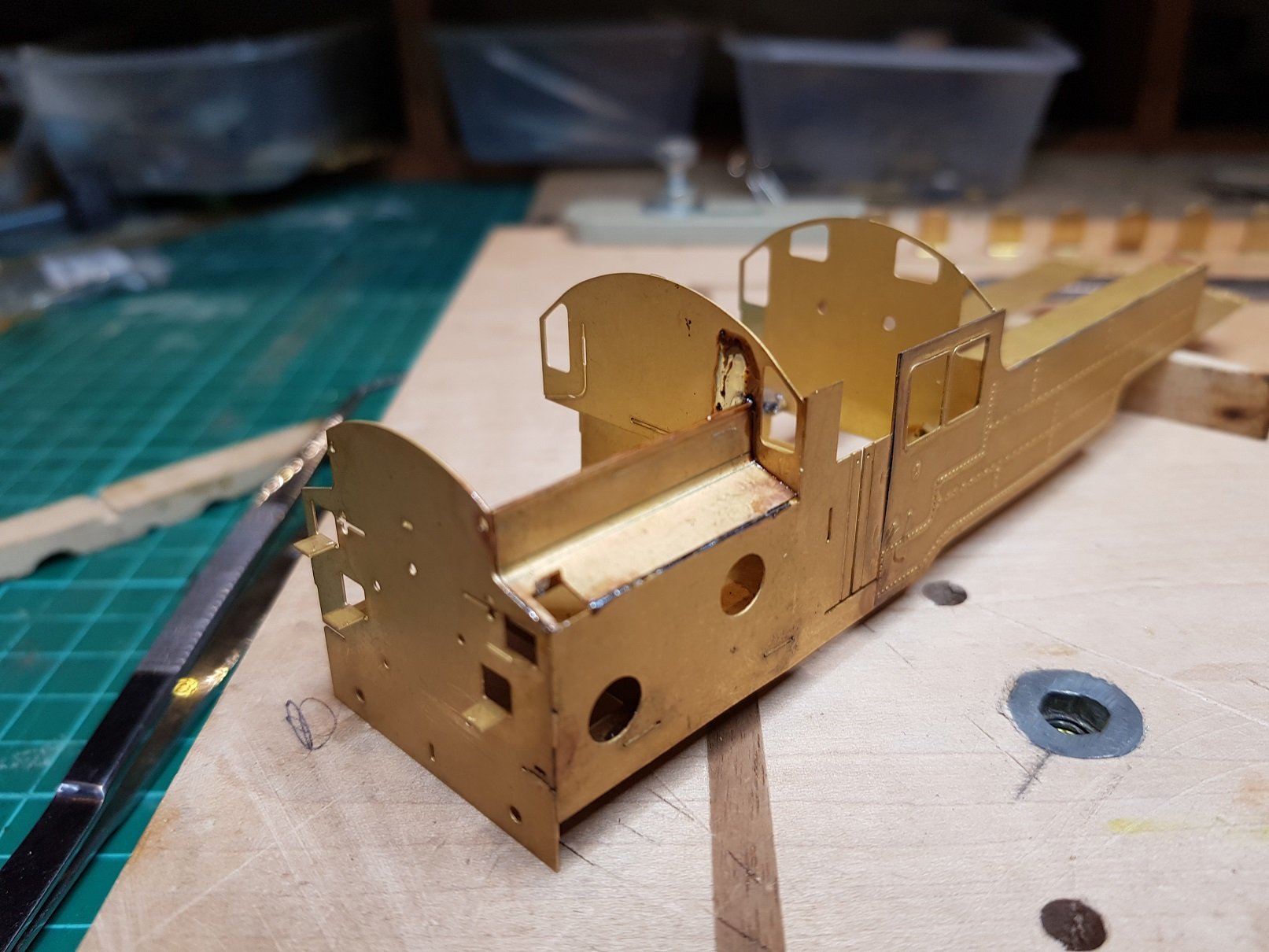
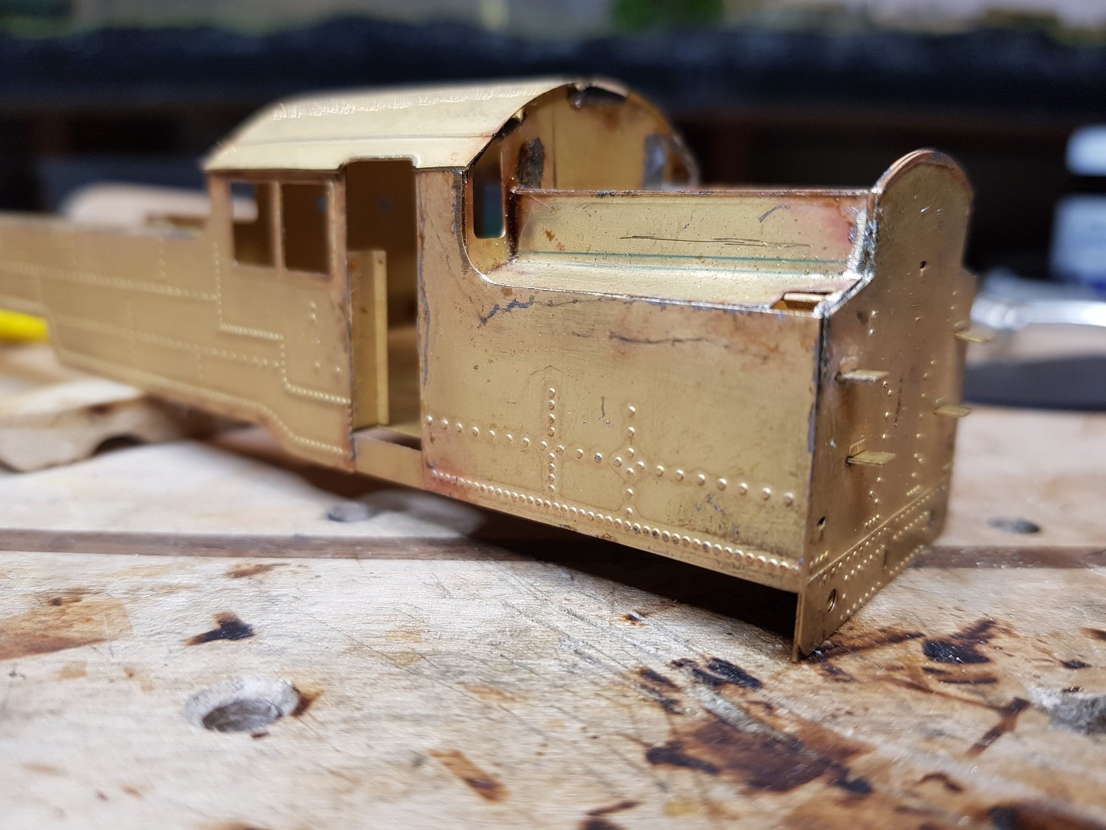
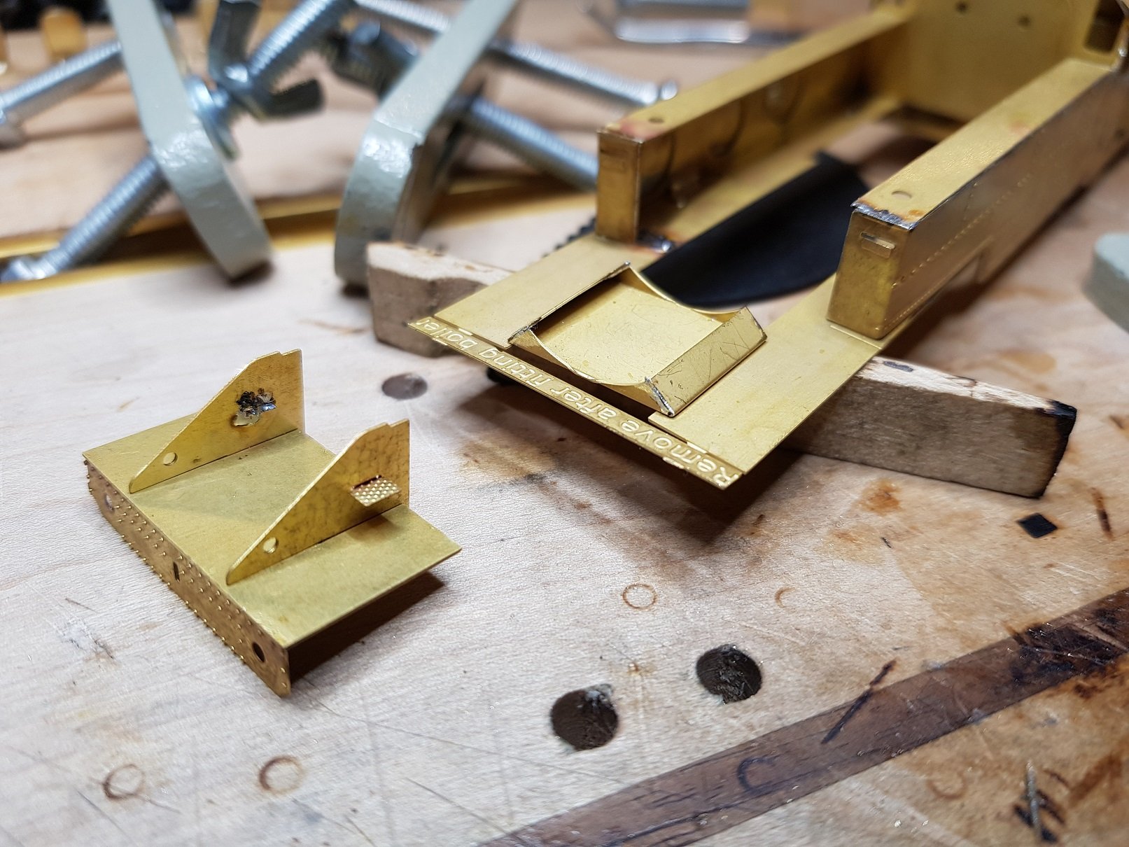
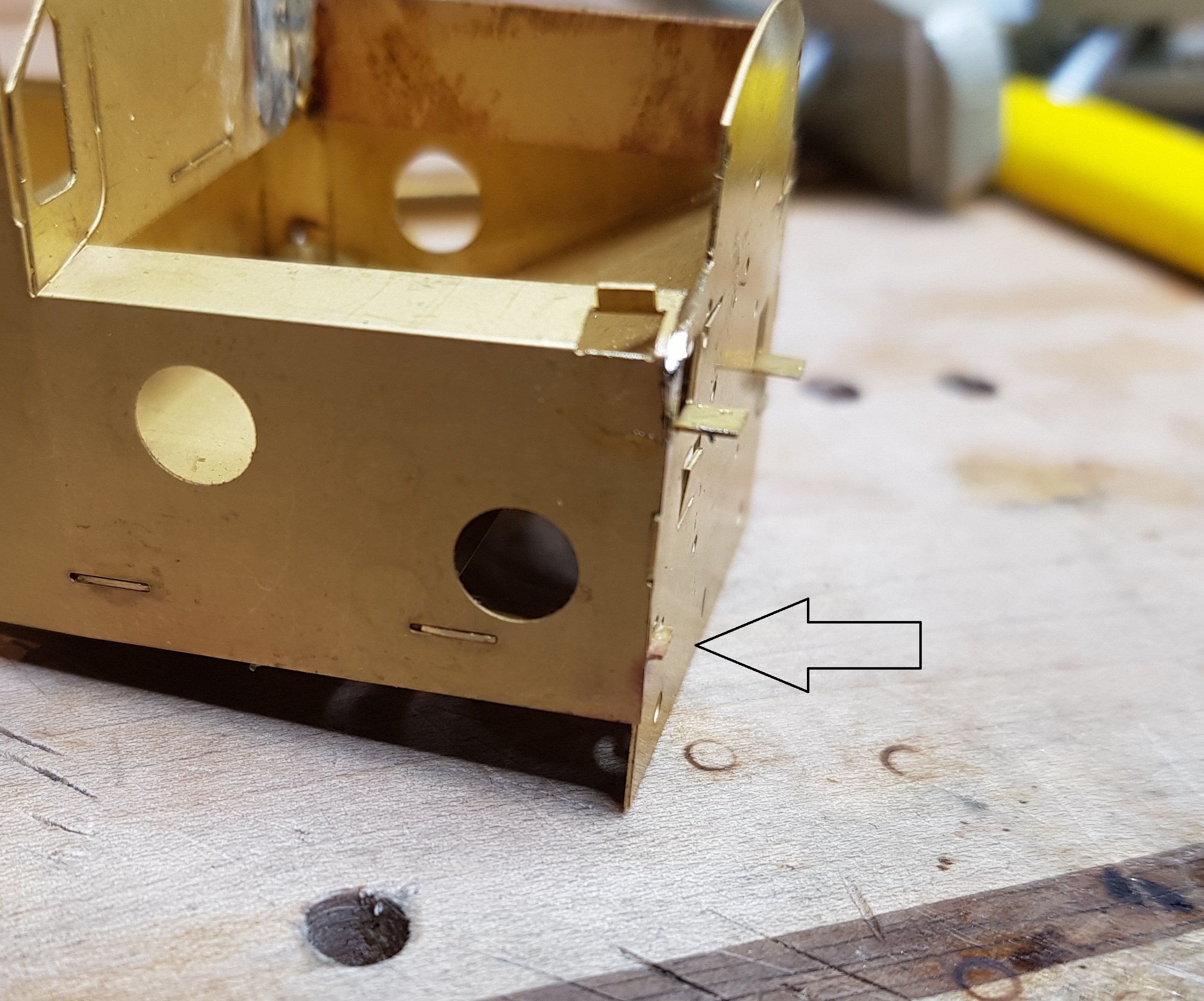
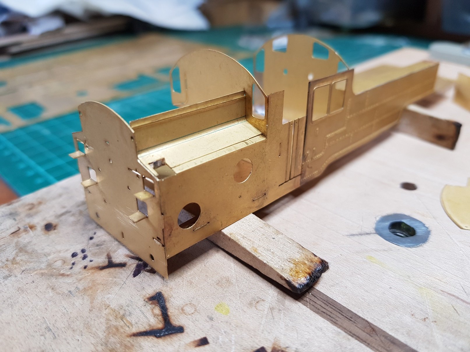
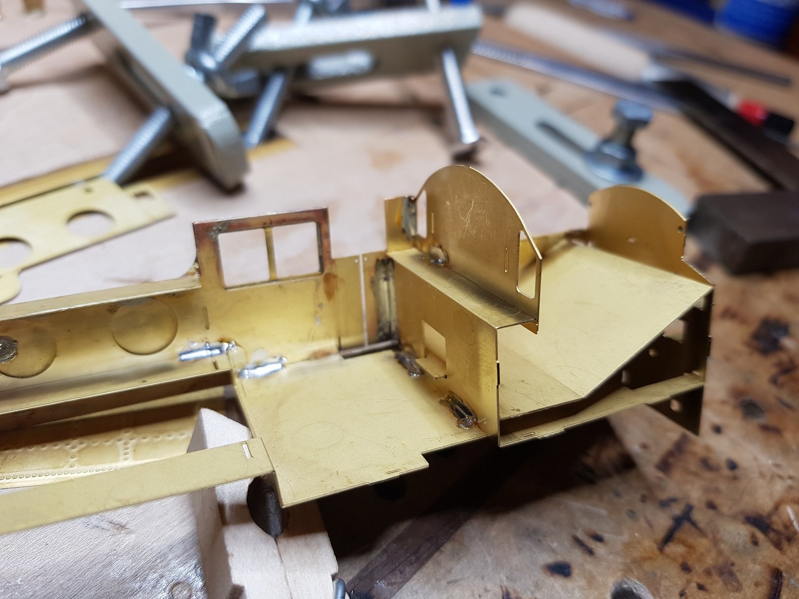
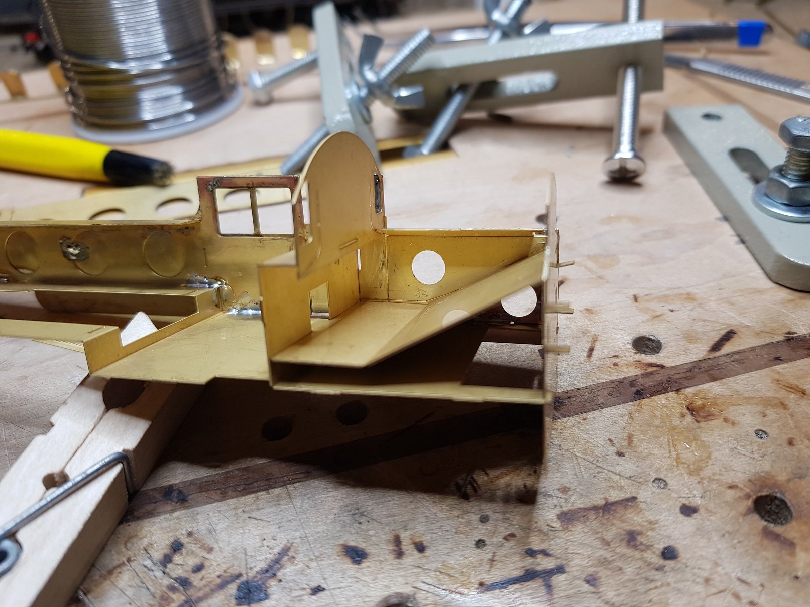
It turned out to be neither. I trimmed the tab back on the suport and moved it down and over to match the overlay. Gives better support & fits better with the overall look. This did leave the slot exposed, but a quick bit of solder plugged it. A little bit of filing here to smooth the surface was need to be sure the rear of the cab looked flush. Going back to an earlier comment regarding tabs. This photo shows how much the tabs can protrude. The tabs on the side have already be filed down so they are flush. So progressing with second side, bunker upper sides & etches to get to a basic body. Detail etches were added for end and rear quarters. The decision to leave them till now paid off, as it was possible to get a tight fit at the rear corner which will be most visible. What is nice about this loco is the tapering to the rear of the bunker from the cab. It's difficult to see in most photos (here & prototype); there is a difference in overall width of c. 1.5mm between cab and rear of the bunker, and looks rather well - I'll take an overhead photo next time to illustrate this. I mention this, as when you line everything up in the rear corner and work towards the cab, you are a fraction short of the door ope on the underframe. Not really noticible , but its worth noting as an issue if others cannot get it to line up. I will need to dress the seams between the rear detail etch & under frame - it looks like a gap in the photo, but I think it is more down to rounding of the edges of the two sections. Some filing, or perhaps filling should sort this. Then we came to the first real problem - the roof. This time the roof fits, but the sides are too high: I had an inkling this was likely to happen as I built, however I elected to go on and sort it when the time came. It took some amount of filing to reduce the height (earlier images will give an idea) & the options here are to file before construction, or once in place. I think that while filing in place is more difficult, it is easier to see how you are progressing in relation to the cab curves. It also means you can angle the filing to allow the roof follow the profile, rather that reaching a right angle. After much filing I managed to get the profile right & fixed on the roof. Here was another problem - when I design & build, I normally leave out the cab floor, so I can fix the roof from the inside - this is not possible due to the footplate design, so fixing on the outside is needed. The solder will need to be tidied up here to ensure crips lines to the roof; bit of a pain, but there is no alternative that I can see. Perhaps a cut out in the floor prior to construction may be an option, with a pach soldered in later to maintain the floor. THe floor will be needed as the view into the cab is quite open. I will have to put crew in, as there is no back head detail, and come to think of it, no real means of painting the interior either. I may cut an ope to give me access to sort these issues, and perhaps screw / glue it into place once details are added. Moving on, I complete the smoke box saddle and lower foot plate. The kit comes with a small third etch with a longer front footplate & intermediate steps. Not sure why the shorter was included in the etch, as most photos of early & late models have the longer front footplate? Moving on to boiler & smokebox now, so will keep you abreast of progress as time permits. Ken
-
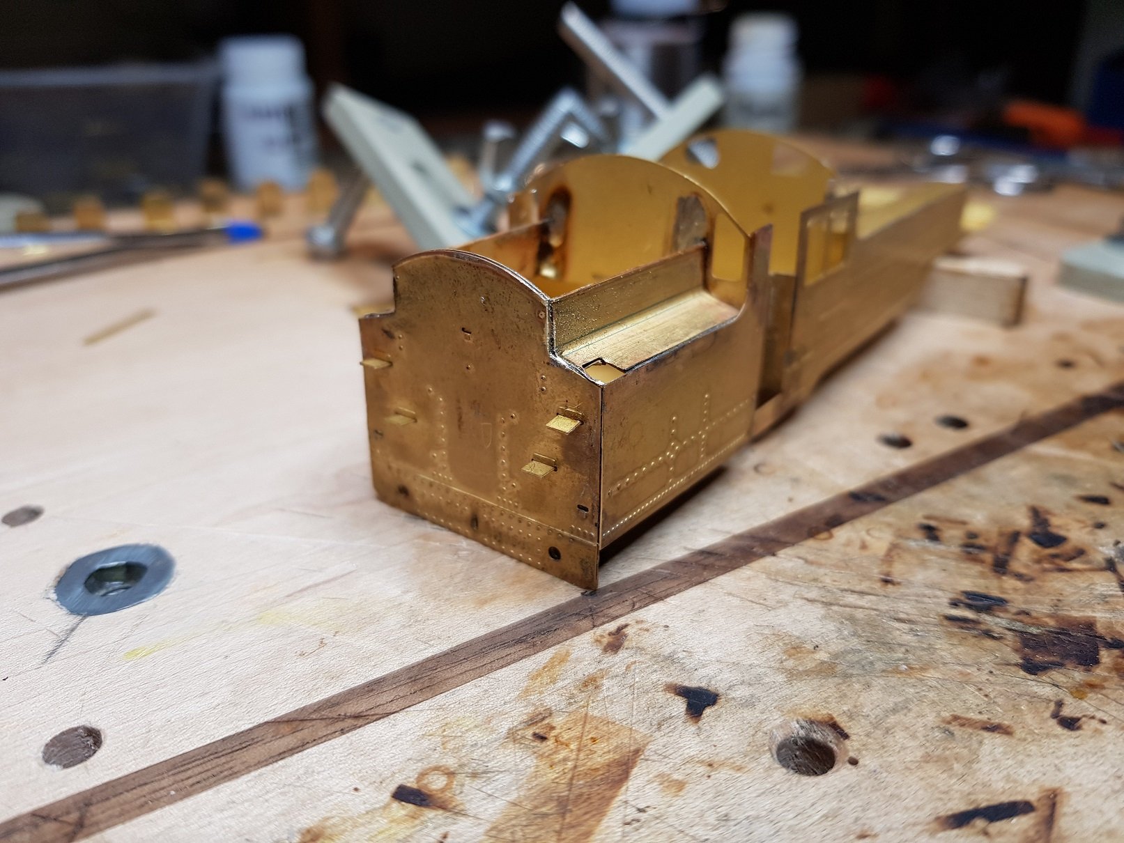
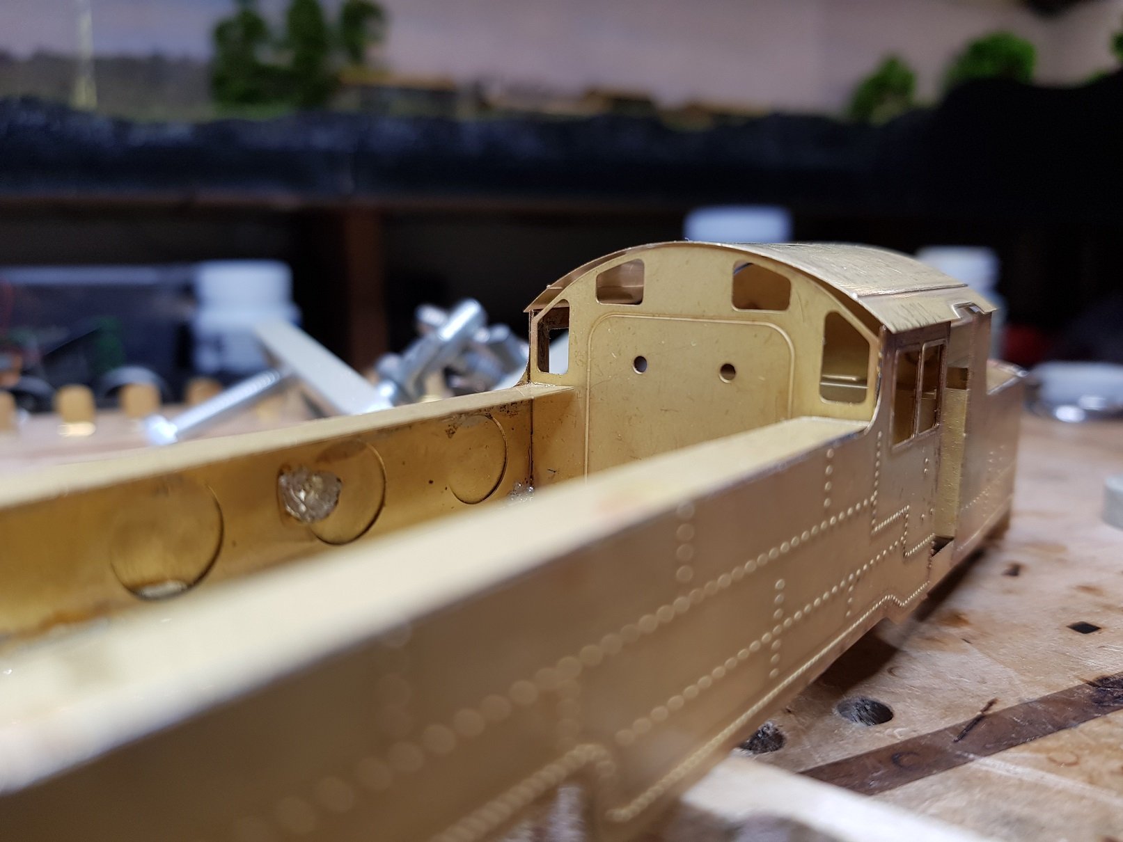
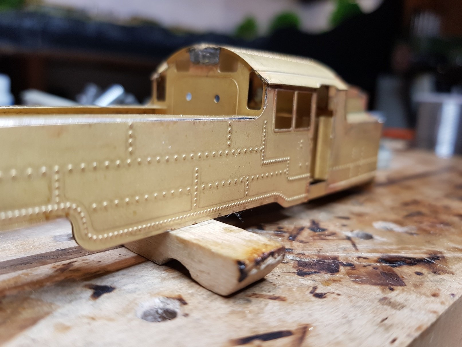
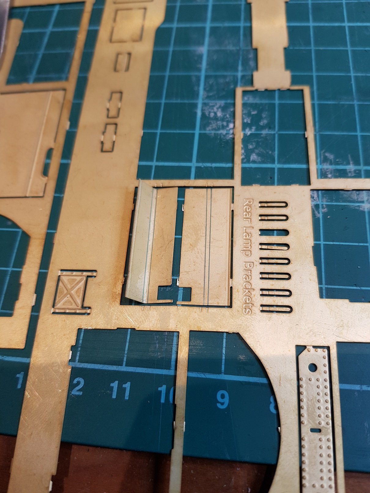
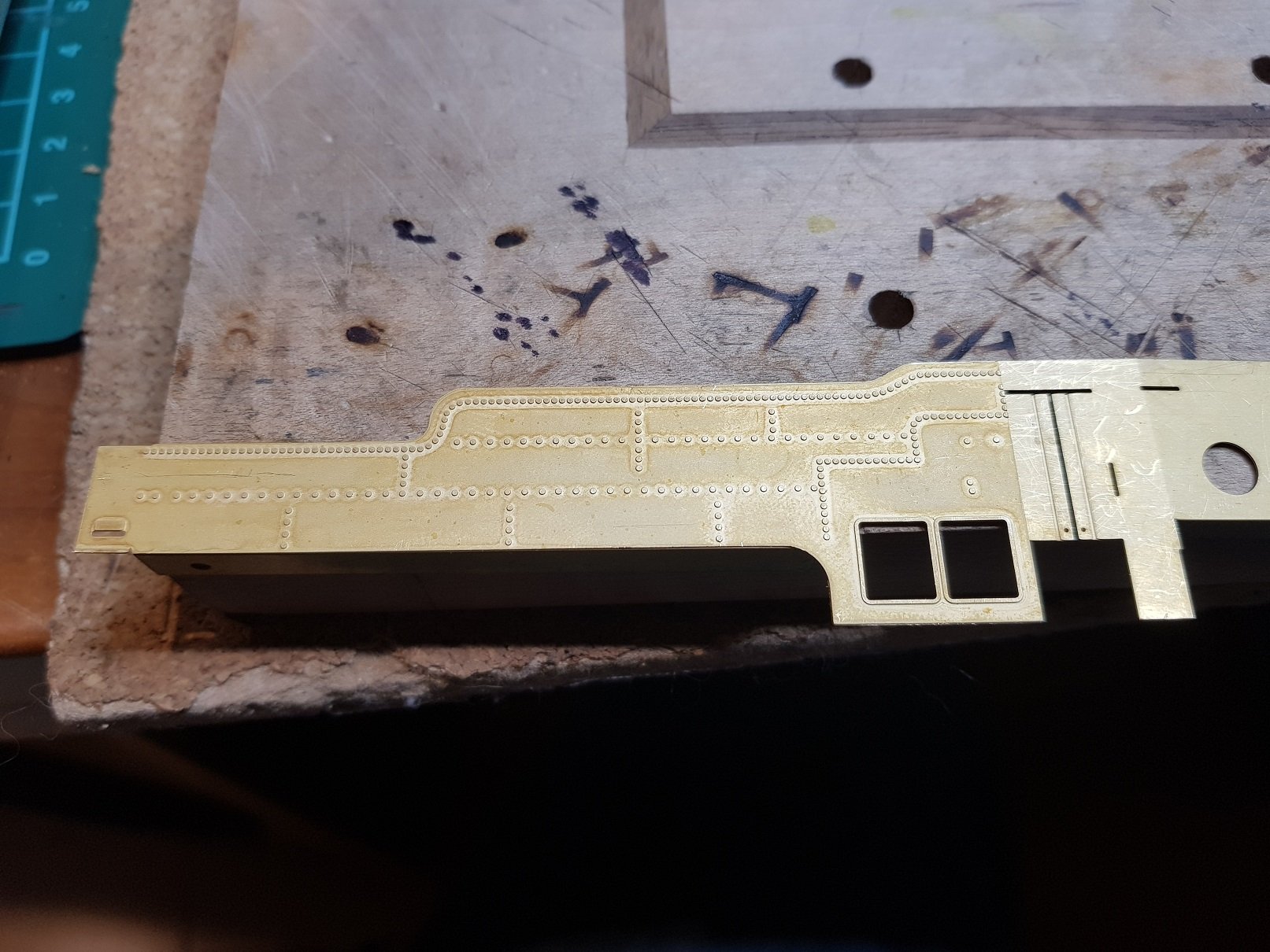
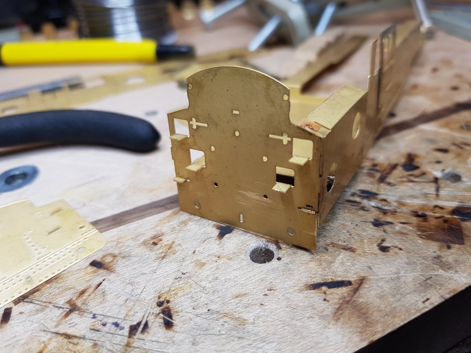
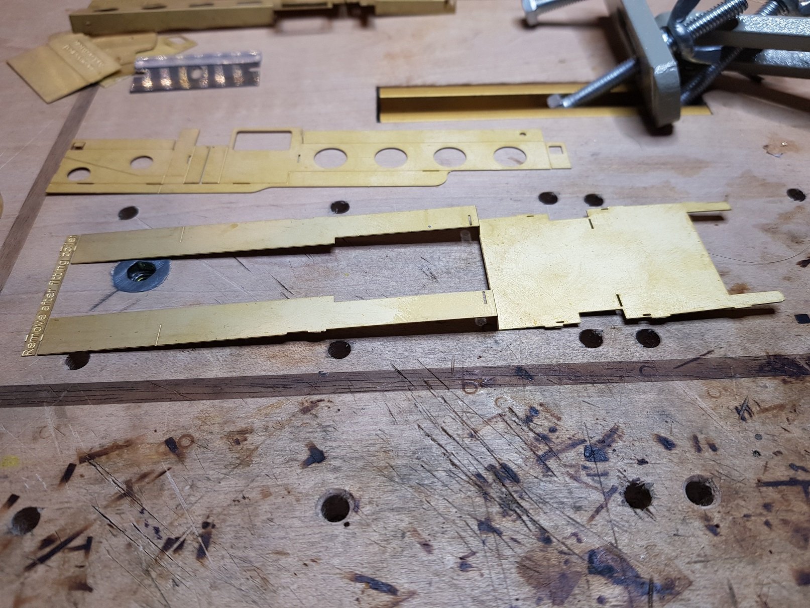
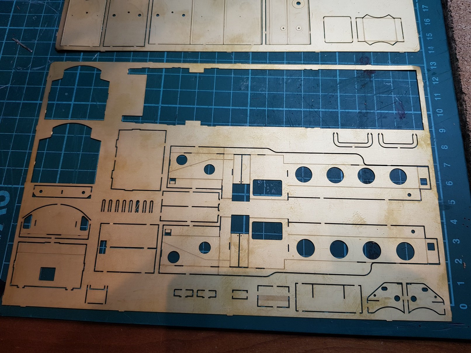
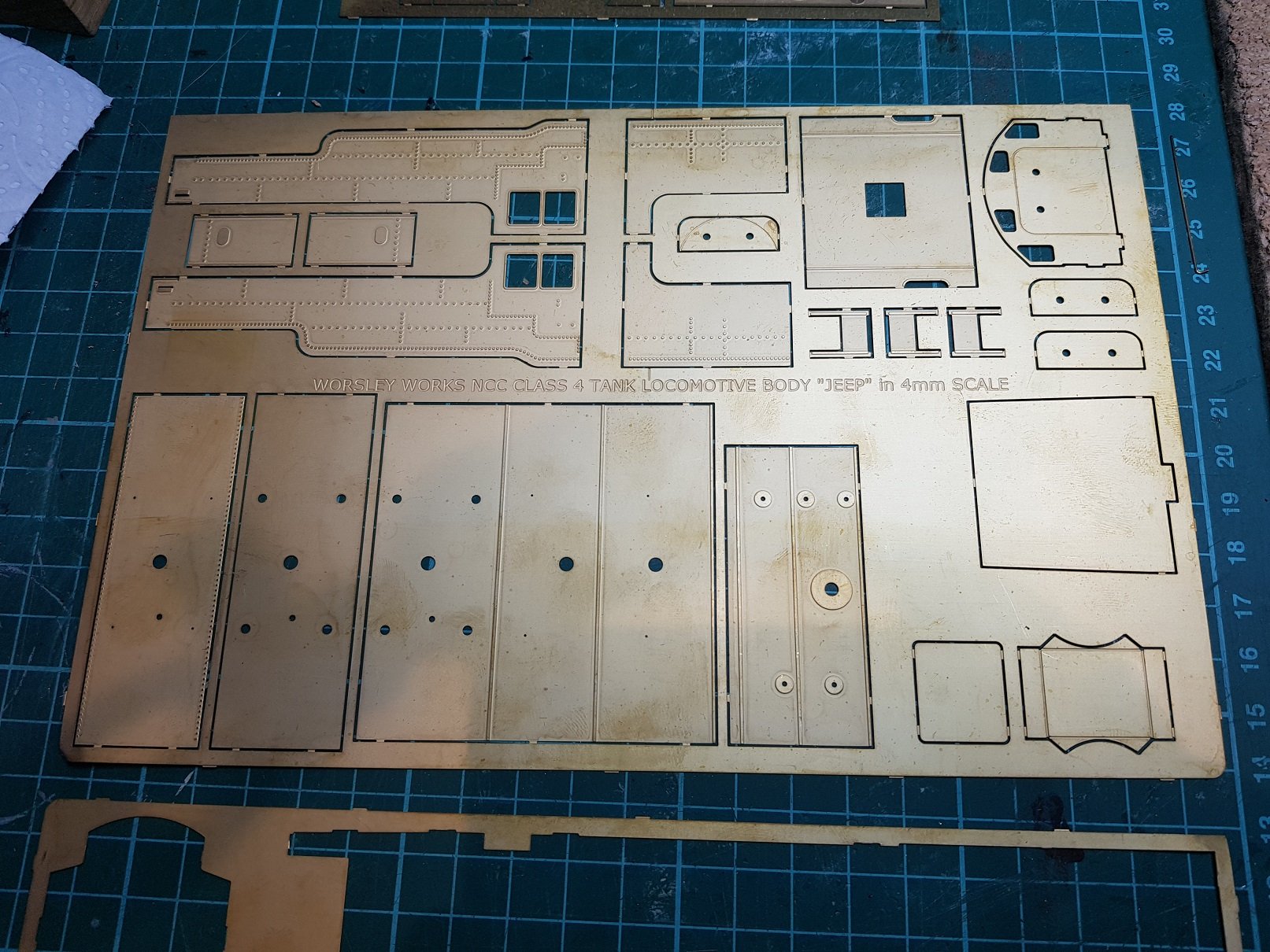
Now for something completely different. Some time ago I purchased the WT Jeep loco body kit from Worsley Works - it really is a scratch aid kit, as it arrives with nothing but the etches themselves. There is some text on a number of the parts in the etch (5), but generally you are on your own. I haven’t seen anyone build one on this site (I’m sure someone will point me to a post), so I figured I would share the journey. First the etches. They have been etched from 0.3mm brass, which is fine for most of the underframe parts, however the detail etches are in the order of 0.11mm which is quite thin and care is needed removing them from the fret and also filing back the tabs. What is interesting is that some of the parts need to be cut from the etch as instead of a tab, part of the outline is only half etched - note the top of the structural side at the top of the cab. Not a big issue, but not immediately obvious. I first removed the footplate and one side etch & associated detail etch to get a look at how they fit. The set in the footplate is easily done and fits very well to the side. On a side note, so far, the kit appears to be very well dimensioned. Things fit together well with minimal fuss, so progress is relatively quick. One issue that needs to be addressed is the tabs are too long – they look short on the etch, but when mated to their associated slot, they protrude too far, particularly where details etches are overlaid. Quick trim with a file generally sorts it out. Long detail side etch was sweated onto the side etch & footplate added. The wrap around for the front of the tank is just a fraction short, but is not the end of the world – I may file back the under frame to match the detail. Those familiar with Worsley etch will have experienced this before. I decided not to add the detail etchs for the end & rear quarter at this stage as I wanted to be sure the detail etches line up on the corners. Bunker base, and cab rear fitted in very well. Bunker upper detailing is proving a head scratcher. The fold over on the side is fine. There is a section to support the bunker upper side overlay which fits in the slot in the cab rear, but when the overlay is added, it protrudes above the detail. The other issue is that the overlay is not obvious in the fret – the two parts appear as one with a fold line, again these need to be scribed apart before fitting. Lines are drawn by me to line up with the indentations in the fret to assist in folding. My options are to cut back the support or leave it out; it may be better to cut back as the overlays are very thin and would prove delicate when handling in the future. All for now, will post more as time permits. Ken
-
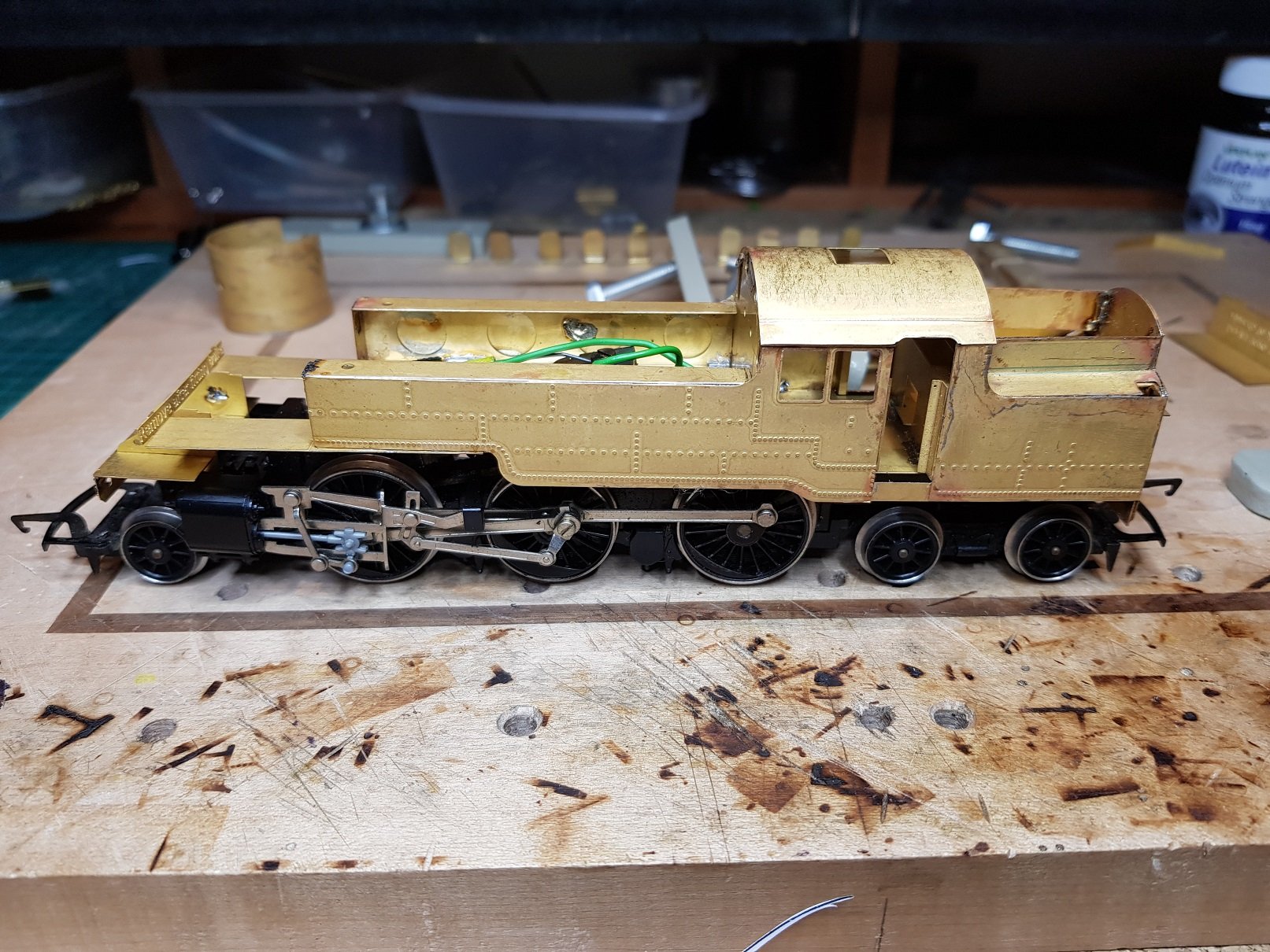
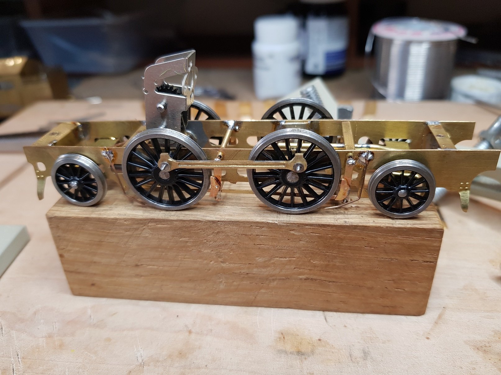
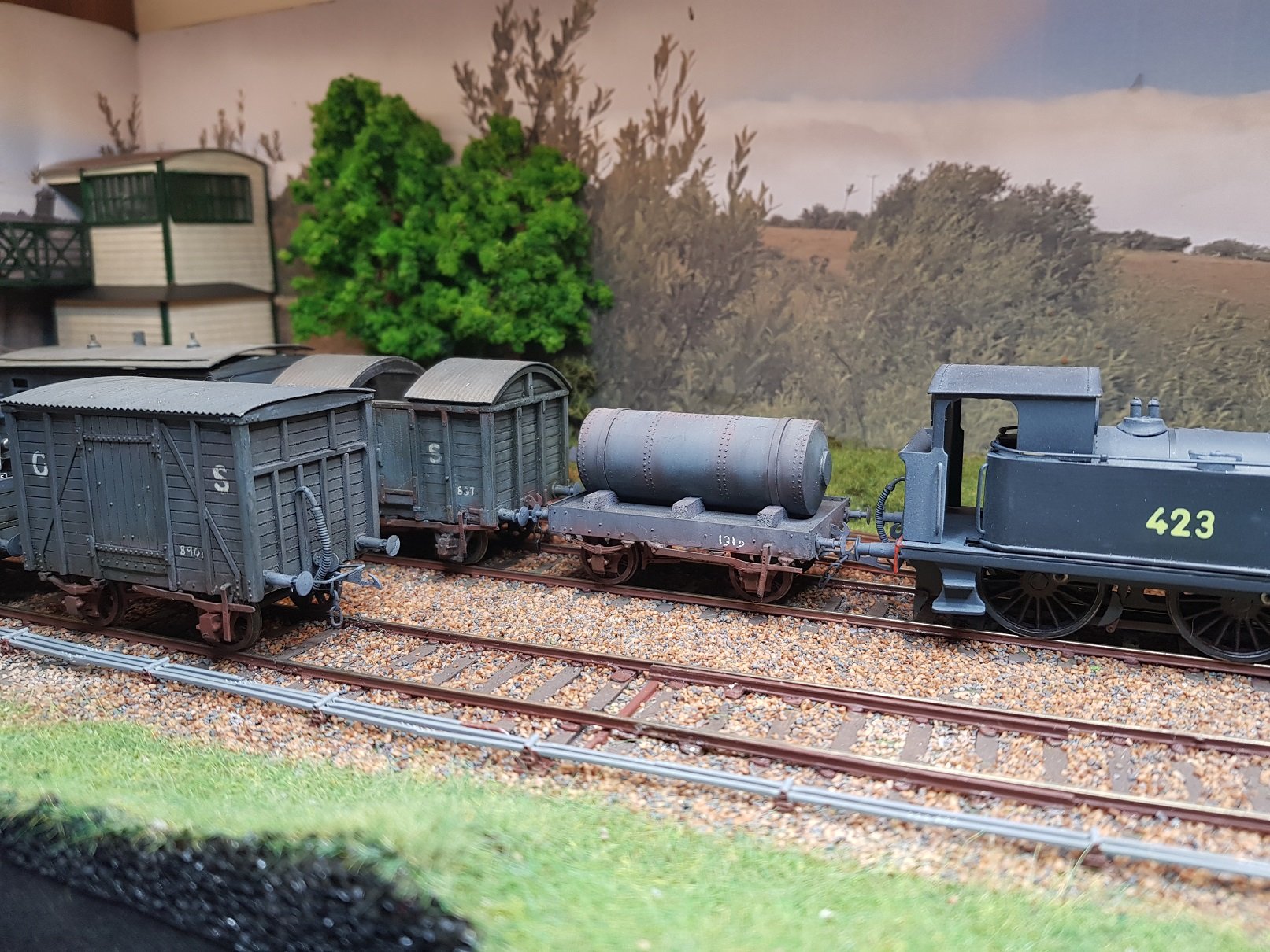
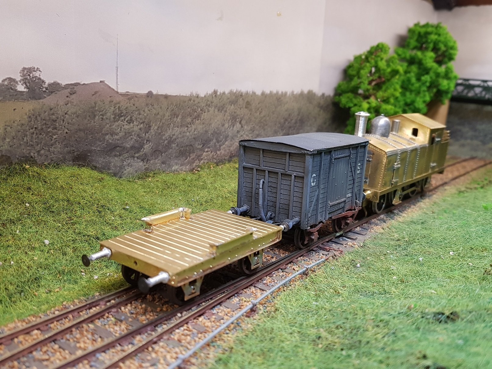
A little more work on the loco over the weekend. Brakes needed to be added as well as sand pipes. Brakes were fashioned in such a way as to be removable - the top pins sit into the cross tubes in the chassis allowing removal for maintenance / painting. One thing that is noticiable ginen the cut-outs in the chassis is the lack of firebox. This is particularly evident on the 423 loco I built, so I decided to put in a fire box detail to fill the gap, so to speak. Perhaps it was a little OTT, as when the body goes back on, you really have to get low down to see the detail. The steps also cover over the front brakes - ah well, at least I know they are there!! At leas the sand pipes are visible. Motor and pick ups were added and it now runs. Pick ups are above the chassis as there is loads of room given the size of the body, and this helps to keep the underside somewhat tidy. I'll park this for now until additional parts arrive to finish the detailing on the wagons, but before I go, some photos of the train extant. All for now. Ken
- 379 replies
-
- 10
-

-

-
When comparing to the photo, it looks fine to me; looking more like the propotype is probably better than trying to make it fit a drawing? I would agree with your earlier comment regarding a cut-out in the foot plate given the height of the boiler. Even if you do not do dummy valve gear, I think it will look better, sometime the dark area inside is einough to give a more realistic look. Fine looking loco, and another fine build I might add. Ken
-
 Angus, Saw your question in my workbench thread & answered there. But again here for convenience. You can always shorten the tank, or lengthen the wagon and add in the headboards & strapping you were referring to in your post earlier. My timber supports are probably a little too big on the model, however it seems to work, so I'm happy to leave it. Regards, Ken
-
Angus, Hopefully this will help? You can always shorten the tank, or lengthen the wagon and add in the headboards & strapping you were referring to in your post in Layouts. My timber supports are probably a little too big on the model, however it seems to work, so I'm happy to leave it. Regards, Ken
-
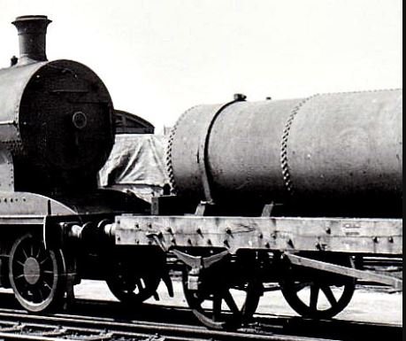
Angus, From my research, they all appear to be different. I know DSER built two, which ran on different chassis up to 1959. They were orgianally built on old short cattle wagon chassis, and I used these photos as the base for my model. I have seen photos of a twin tank units, units with head boards etc, so it's really down to what you want to model. What I do know it is very hard to get a complete photo of one of them. If you are interested, I can give you some details of the model I built. Ken
-
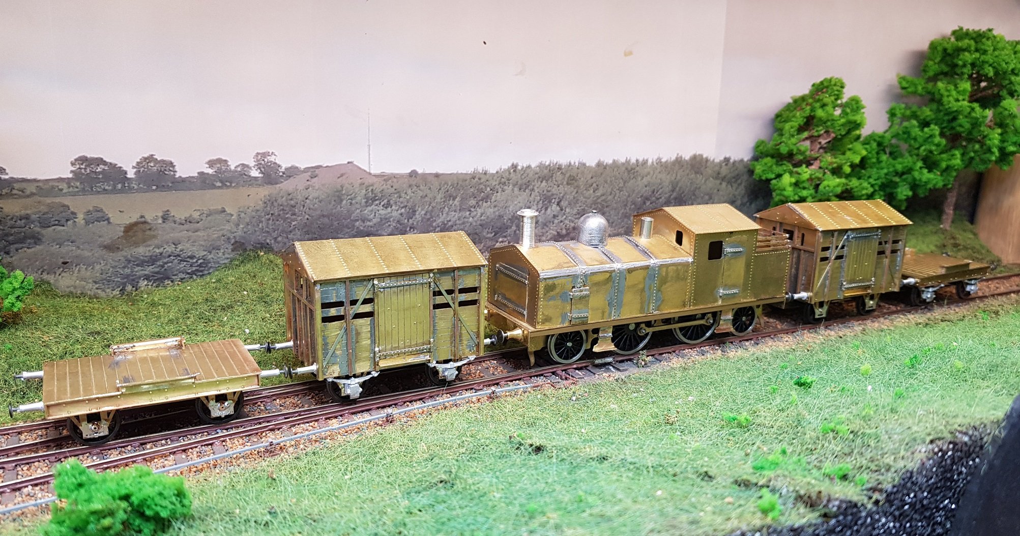
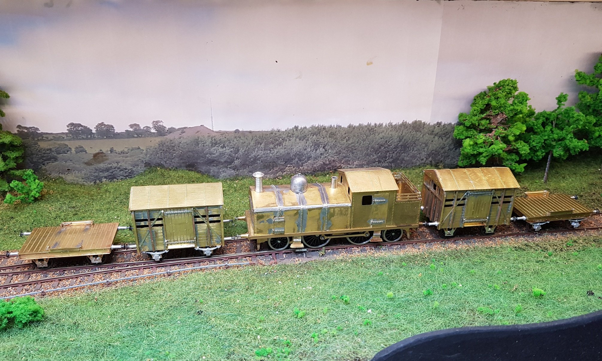
Been a while since I last posted. Been working on a 305mm/ft project which has taken up quite a bit of time! Back to modelling recently. I debated whether to build moulds and cast the sides for the wagon, or just cut an solder, and as I'm very low on mould material I went for the cut & solder method. Wondering now if I should gone the other way given the time needed to add all the posts to the wagons. Anyway, wagons mostly complete. Ran out of axleboxes, springs & brake gear, so two wagons got further than the others. Still plent of detailing to be done when parts arrive, but it's starting to look like a train now. As the train will only run as a complete unit, I may opt for the 3-link coupling which will look more prototypical. More, once parts arrive..... Ken
- 379 replies
-
- 11
-
-
-
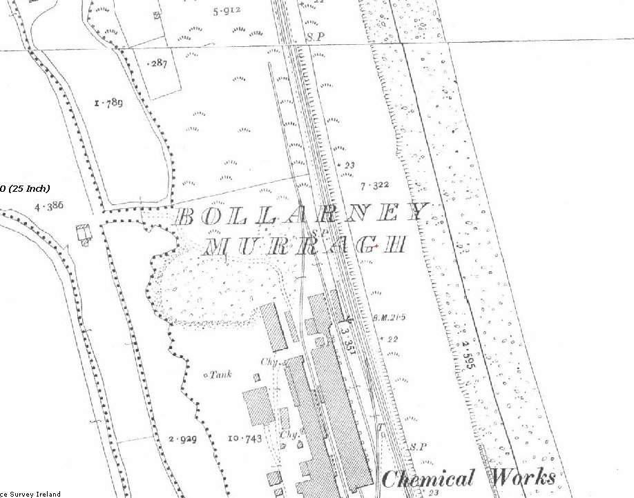
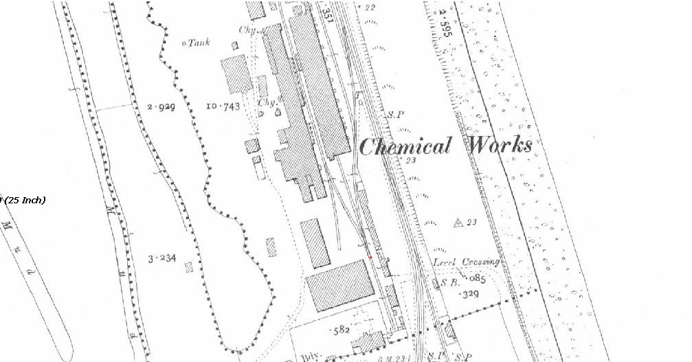
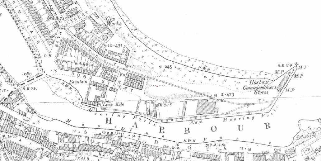
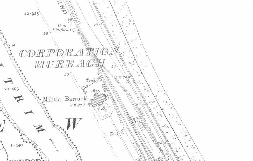
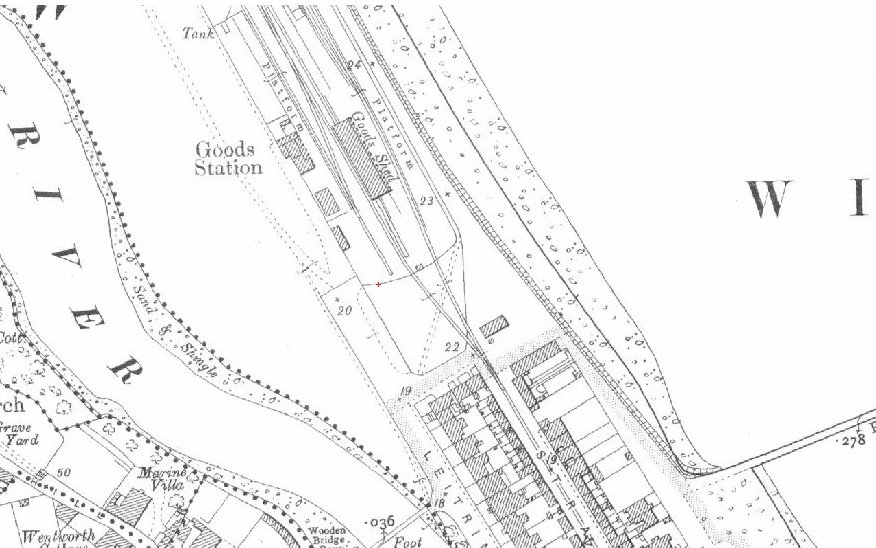
JB, Have you got any more photos of Murrough or the Chemical works in Wicklow? My neck of the woods and was lucky to amble over the remains of the track (c. '88) near the junction SB - points still worked. Track long gone now & very little remains. What made the station interesting was the line continued down to the docks where a line ran along the quay wall down to the lime works. Have a hankering to model this station, however it would need considerable shortening, as it extended for a long way from the chemical works down to the port. Regards, Ken
-
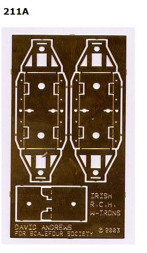
Hello Mark, I'm working in 21mm and picked up my gauges from the Scalefour society: They also do compensated W-Irons, however I find the SSM units are much better. plus the SSM etch includes brake components. They do rivet & ply system for track. Pre-driilled sleepers & rivets are also available. Hope this helps. Ken
- 309 replies
-
- 3
-
-

-

-
- mgwr
- 21mm gauge
- (and 1 more)
-
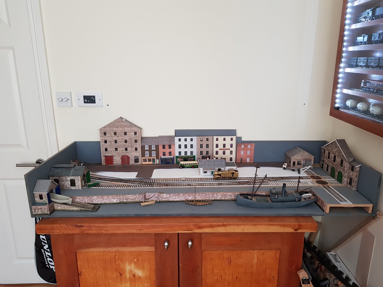
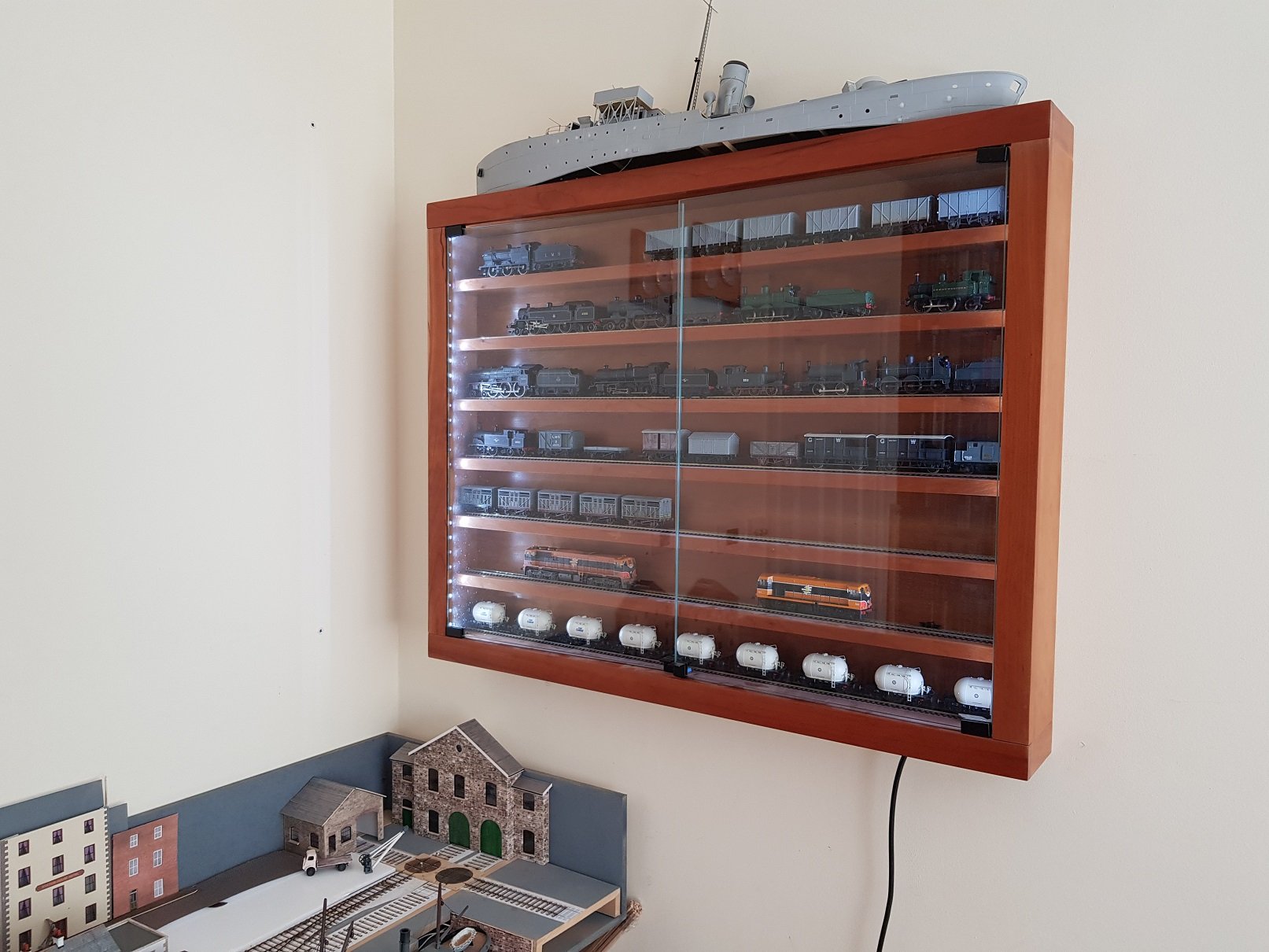
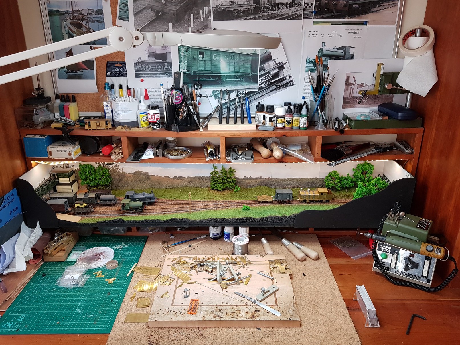
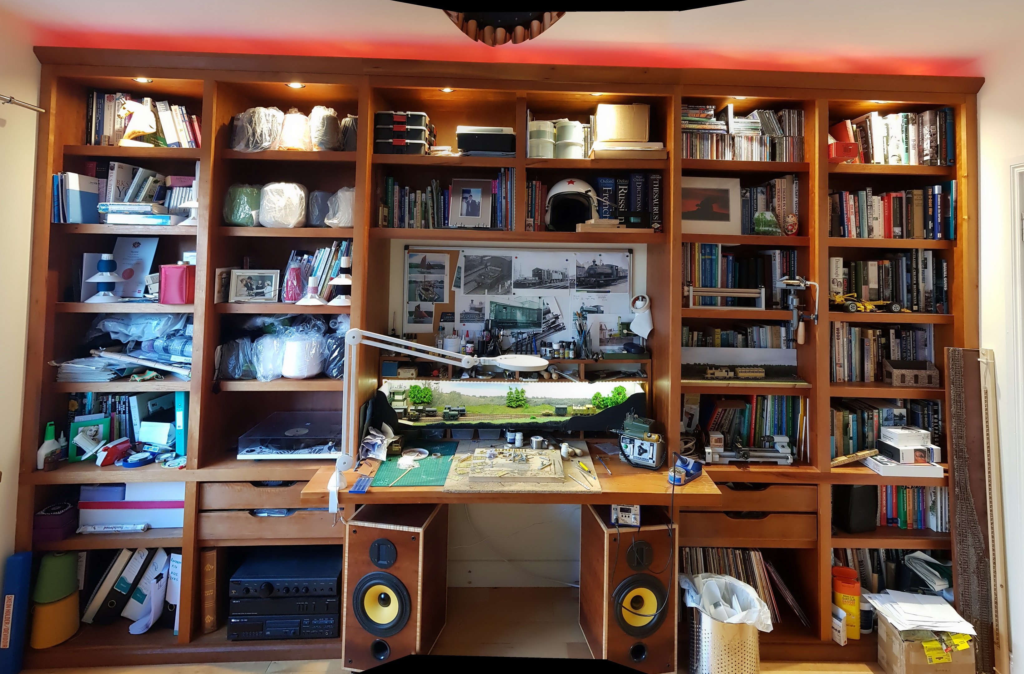
My main work area is in the Library (grand title ascribed once I moved my office out to another room). The libray was built both as a library and my office as I work from home. The room is on the side of the house, so doesn't get much sun / light, so I moved my office a rear bedroom which then freed up the Library for hobby use. Main work area is the original built in desk. Storage kinda apread out across the library shelves. First broadgauge model was the port "Port Cumtha" which I stopped working on for a few reasons, one it was fictitious (not a big issue, I know, but I wanted something closer to the prototype), track was steel, and also points were too tight for hand built models, particularly six coupled locos. I moved to "Wicklow South" as it is smaller & esier to move. Layout is resing on a cabinet built to house a two drawer filing cabinet to match the library construction. A display cabinet followed which is mostly filled with UK stuff I was attempting to re-purposed before I took up scratch building, so most of this lot will go up for sale at some time in the future. Space being made however for more Irish related models - some broad gauge track will be added at some point to replace the OO. Again cabinet built to match the rest of the fittings. Ship on top is the Corvette kit in the long term process of being built to represent MV Cliona from the late 40's. Work area with "Wicklow South" just above the work desk. I find the white board is good for putting up photos of the prototype when building for easy reference. Mill is in the wood workshop out back - will follow up with photos later. Now, all I need to do is get back to working on the models at some point! Ken
-
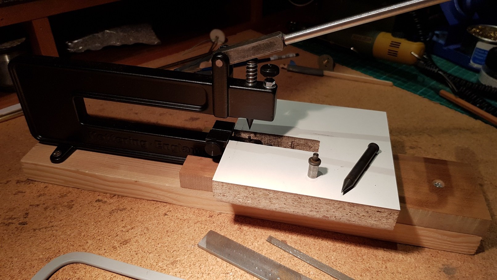
Nah - that's a Kettering unit. I find it works better with a sliding suport table. Not being a rivet counter or anything........
-
GSWR/GSR/CIE Six-Wheeled Coaches - ECMbuild in Gauge OO
KMCE replied to murrayec's topic in ECM Model Trains
Superb work Eoin, These kits appear to be much more detailed than the Worsley kit. I may be tempted to indulge in a few. Few quick question, if I may;- The bogie & trailing wheel arrangement looks interesting, however how effective is it? - I found the Cleminson chassis too slow to react & provide a smooth transition through points etc. I ended up using the PB wire method you kindly recommended, which does work well. I presume these can be built for 21mm? I noted the centre axle has brakes on the model you demonstrated- do all kits have centre brakes, as i understood, only some coaches had them? Cheers & good luck with the rest of the build. Ken -
David, Saw this and thought of you! The Unbuilt Engineering of the Transatlantic Steamship and Railway Route via Belmullet, Co Mayo 1820-1920 On Monday 10th February 2020 at 6:30 PM in Engineers Ireland, 22 Clyde Road, Dublin 4 In this presentation Richard Butler, Lecturer in the Historic Built Environment at the University of Leicester, will focus on the unbuilt engineering of a railway from Dublin to Belmullet and the development of that town as a transatlantic steamship harbour. In the early days of railways and steamships, many western Irish ports were suggested as suitable for making a faster and safer route between the ‘Old’ and the ‘New’ worlds – connecting Britain and North America via what would now be called an Irish ‘land-bridge’. Though Belmullet never achieved this status, it was the focus of sustained attention from engineers, hydrographers, and government commissions from the 1830s until the coming of Irish independence. Regards, Ken
-
Seriously impressive stuff David. Really love those railings in the second last photo. The buffer stop and loco shed just hit a new level of realism....
-
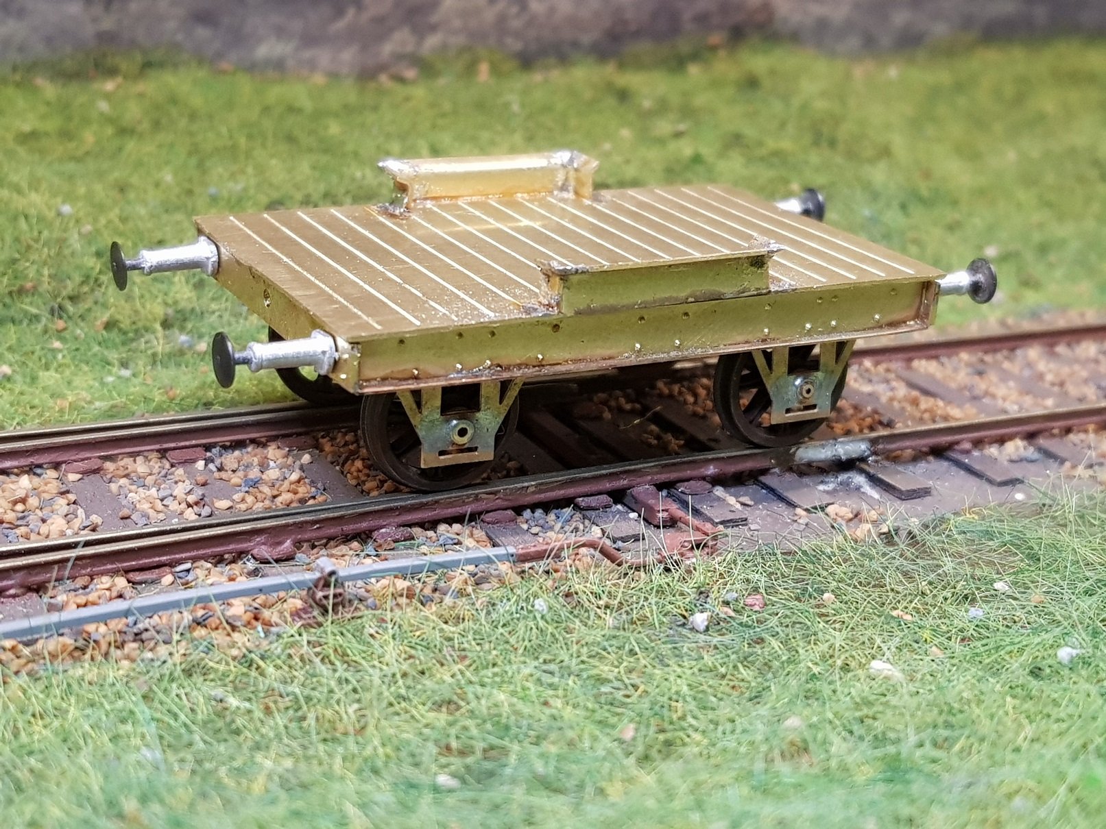
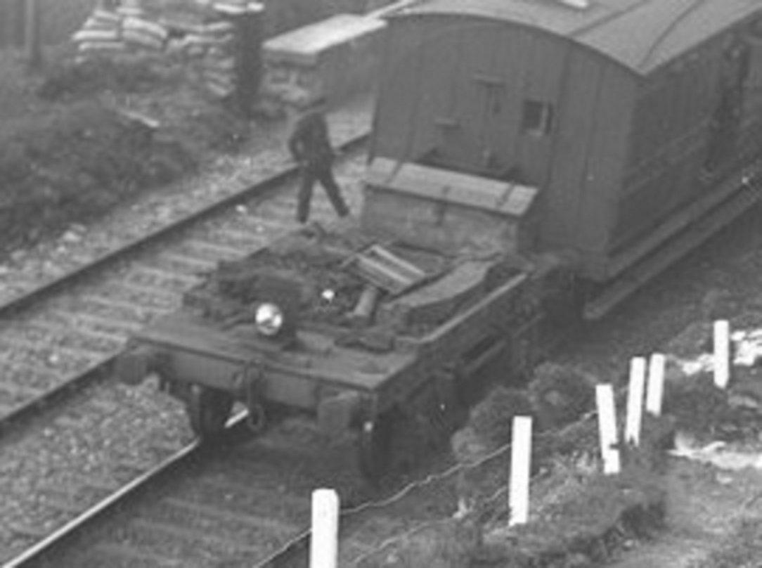
My understanding is that the flat wagon was to carry repair tools and materials to fix any sabotage on the line. As to the upstands, they are quite unusual & I dont know the answer; perhaps they are to provide some means of stopping material falling off whilst providing repair crews quick access during repairs?
-
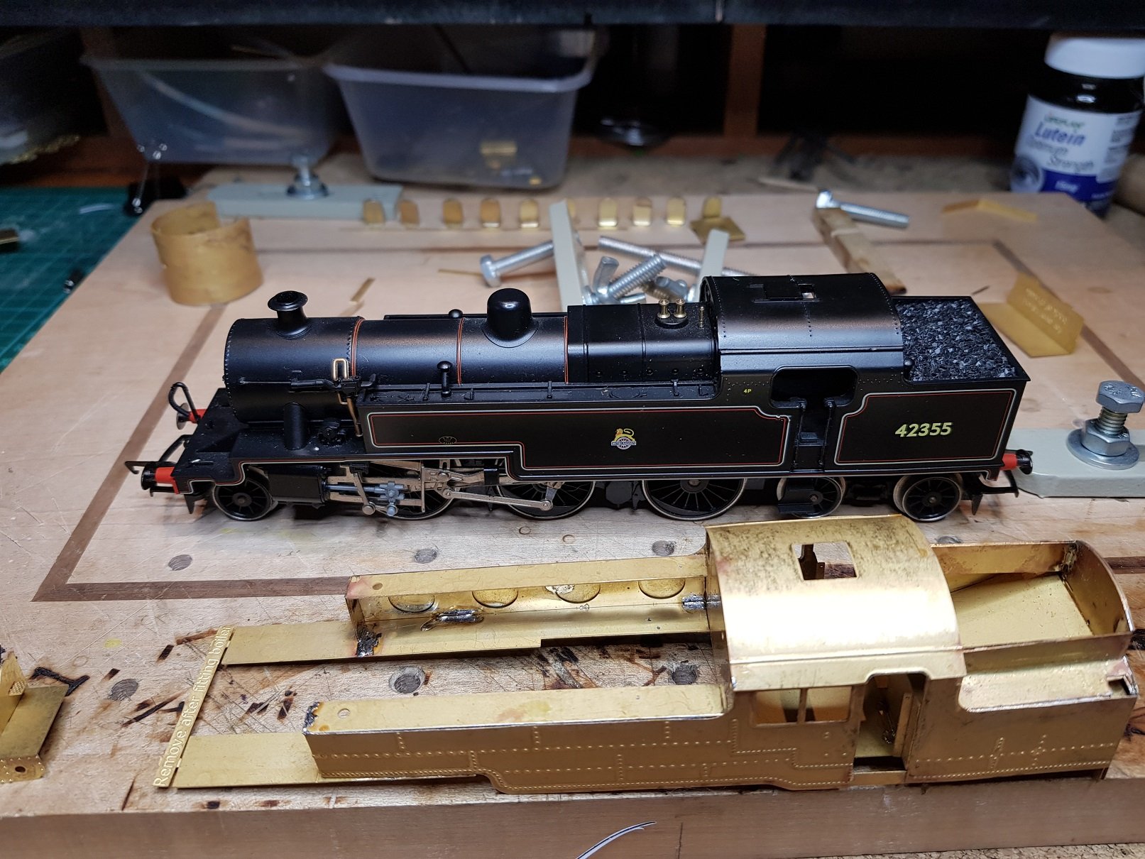
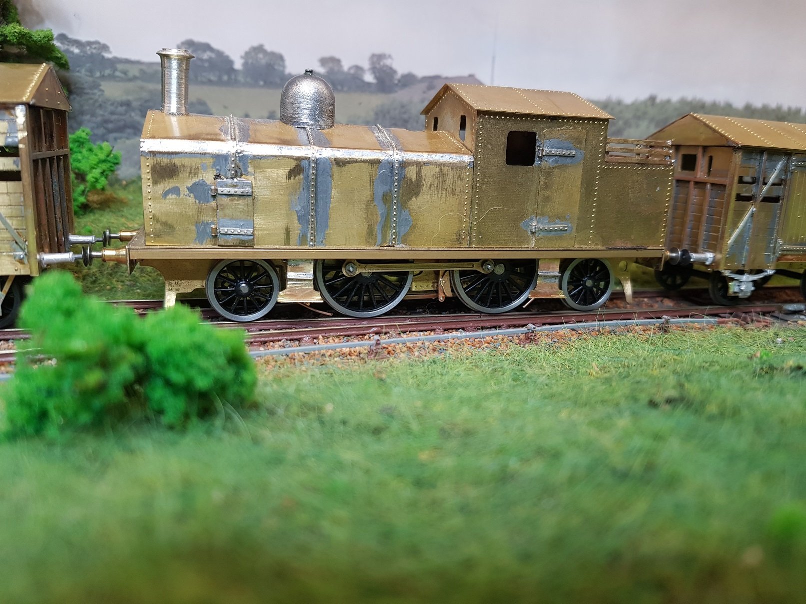
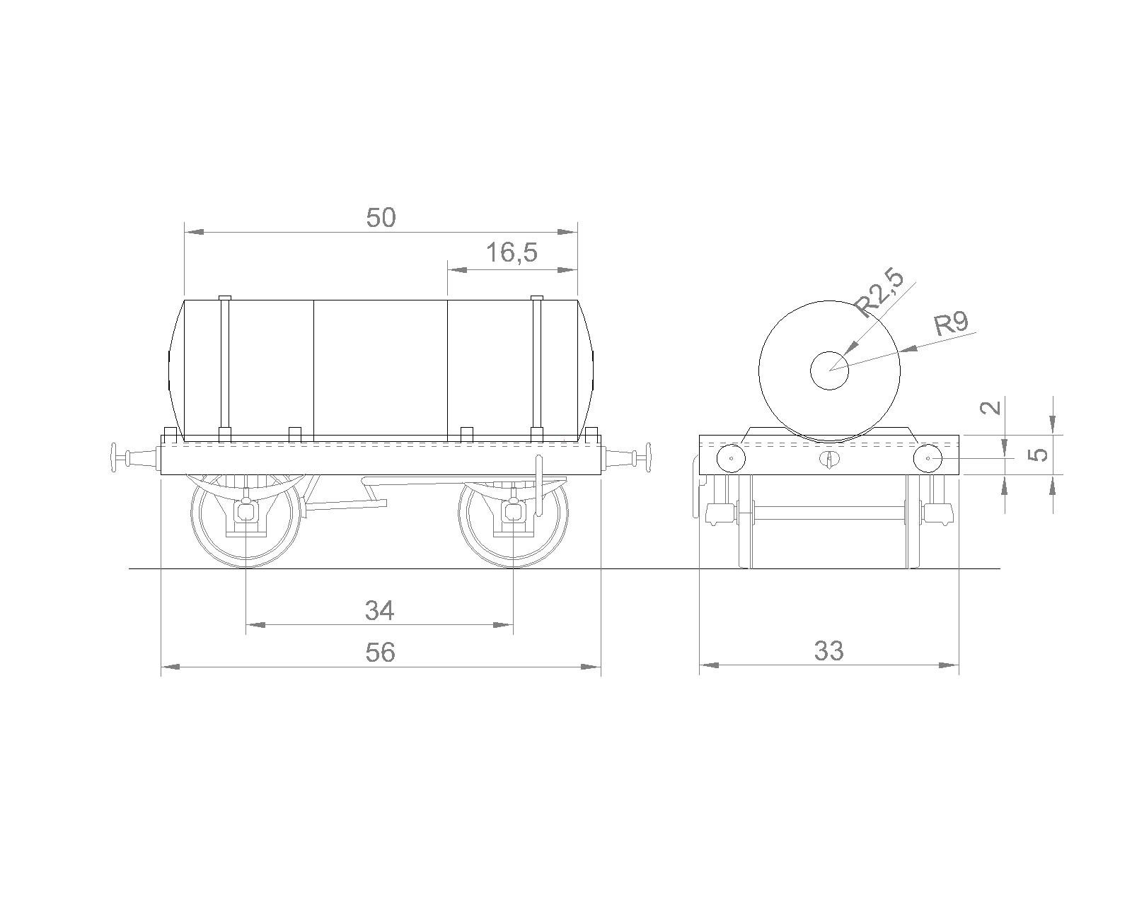
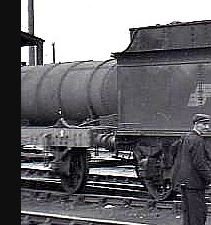
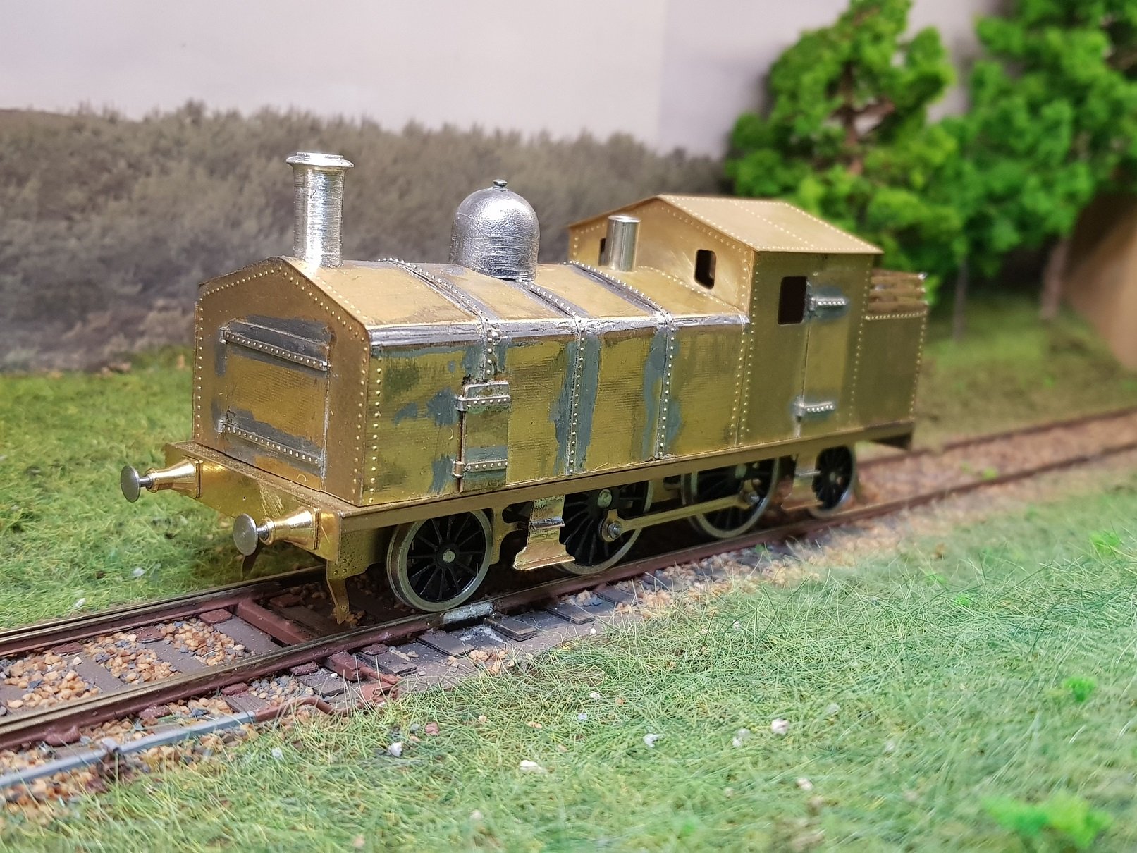
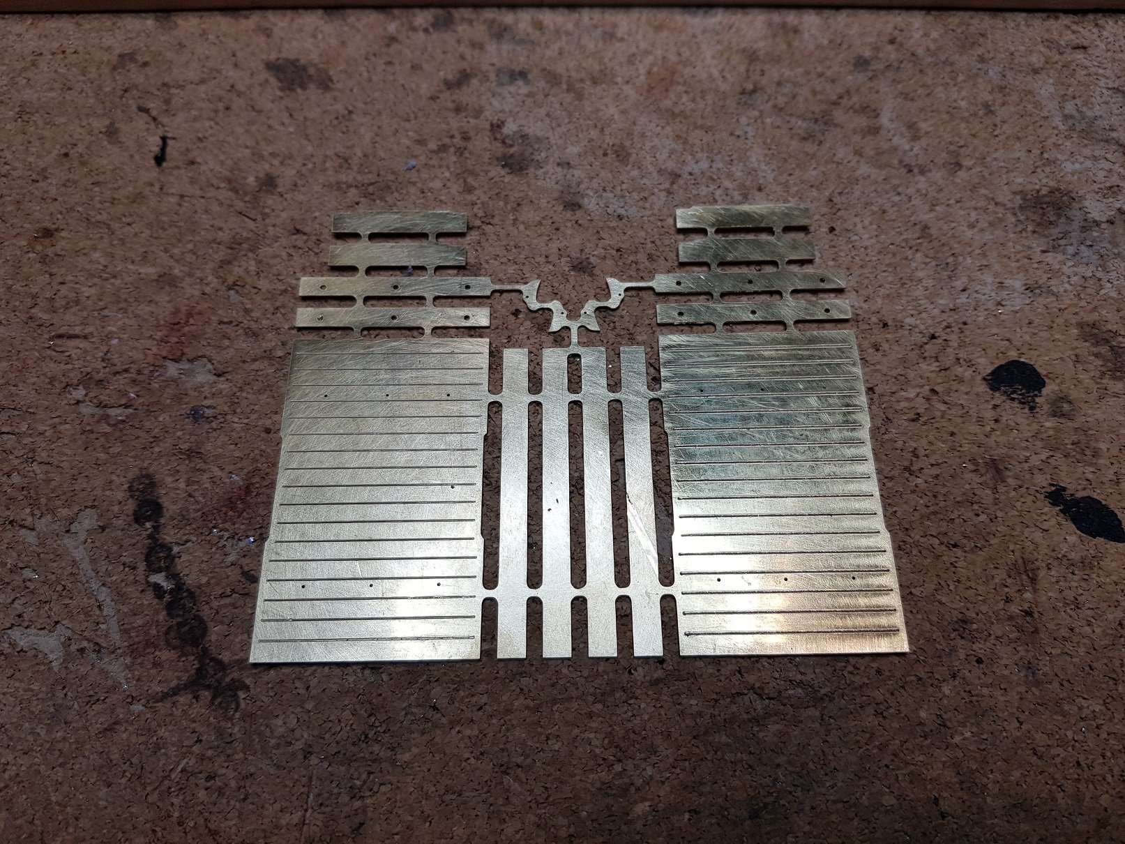
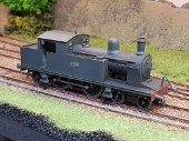
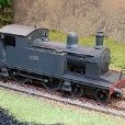
Been quiet for the last while, but got some work done. The loco body was sanded and leveled to sit better on the chassis, side steps andded and coupling rods fixed in place. Gearbox and motor housing are also installed ready for pickups. Cover on the safety valves needs to be bigger so that will need to be re-done with brass tube. Smoke stack and steam dome were turned down and tidied up with the lathe, Moved on to the flat wagon and sketched up a kit to cut on the mill. While I was at it, I included some brake shoes for the loco, as I forgot to include them in the loco cut. This will allow me to proceed with the loco build later. This cut is for the two wagons as it made sense to cut the two at the same time. This was a tricky little wagon, as it's not quite flat. There are raised & curved upstands located in the centre of the wagon, so I allowed a cut-out in the sides to take these upstands, which were flared at the top, turned in and corners shaped with solder. From what I can see from the few photos I have seen is that they are only on the sides, turn in slightly, but do not cross the floor of the wagon. Kinda hard to explain, but this grainy photo may help... So, have got to the rolling chassis stage with brakes, axle boxes, springs & hook to be added. Bit of tidy up of the solder to be done & add the white metal parts to finish. Then rinse & repeat for the second one! I'll make up some odd work tools & parts as a load to finish them out later. View of the loco, wagon & the box van stepping in as a sub for the troop wagon to get a feel for how it is coming together. More as time permits! Ken
-
Alas, no. Modern Health & Safety has all but eliminated natural selection!
-
Superb work John. I particularly like the Firebox jig as a means of holding that section solid whilst applying the wrapper - very clever. Ken
-
This may help? Regards, Ken
-
Superb work Eoin. I am particuarly impressed with the expasion link construction as I konw how difficult it is to solder up small parts. Excellent build & looking forward to seeing more. Ken