KMCE
-
Posts
540 -
Joined
-
Last visited
-
Days Won
29
Content Type
Profiles
Forums
Events
Gallery
Blogs
Store
Community Map
Everything posted by KMCE
-
I don't like that Global Shipping Scheme. I have had a few items damaged in transit - no matter how well the seller wraps the item, the global shipping centre re-pack it to reduce weight. When I got in touch with the seller and showed the photos, they were quite annoyed as they had packed properly & had to get in touch with the GSS. Got it sorted, but the seller must of had a hell of a battle with the GSS
-
I have found that using de-soldering braid similar to this works rather well: https://www.circuitspecialists.eu/mg-chemicals/solder-wire-wick-and-flux/?mgproducttype=77 By placing the braid over the solder blob, touch the iron to the braid & swipe away. Some people recommend using flux, but I have found it operates fine without the flux. It leaves a very fine layer of solder similar to tinning, but much finer. A quick rub down with a brass brush smoothes everything out. Obviously the braid needs to be fresh each time as it quickly soaks up the solder, so you just cut away to a fresh section each time you use it. No files used, just the braid & brush. Worth a try. Ken

-
Now that is proper quality.......well done.
-
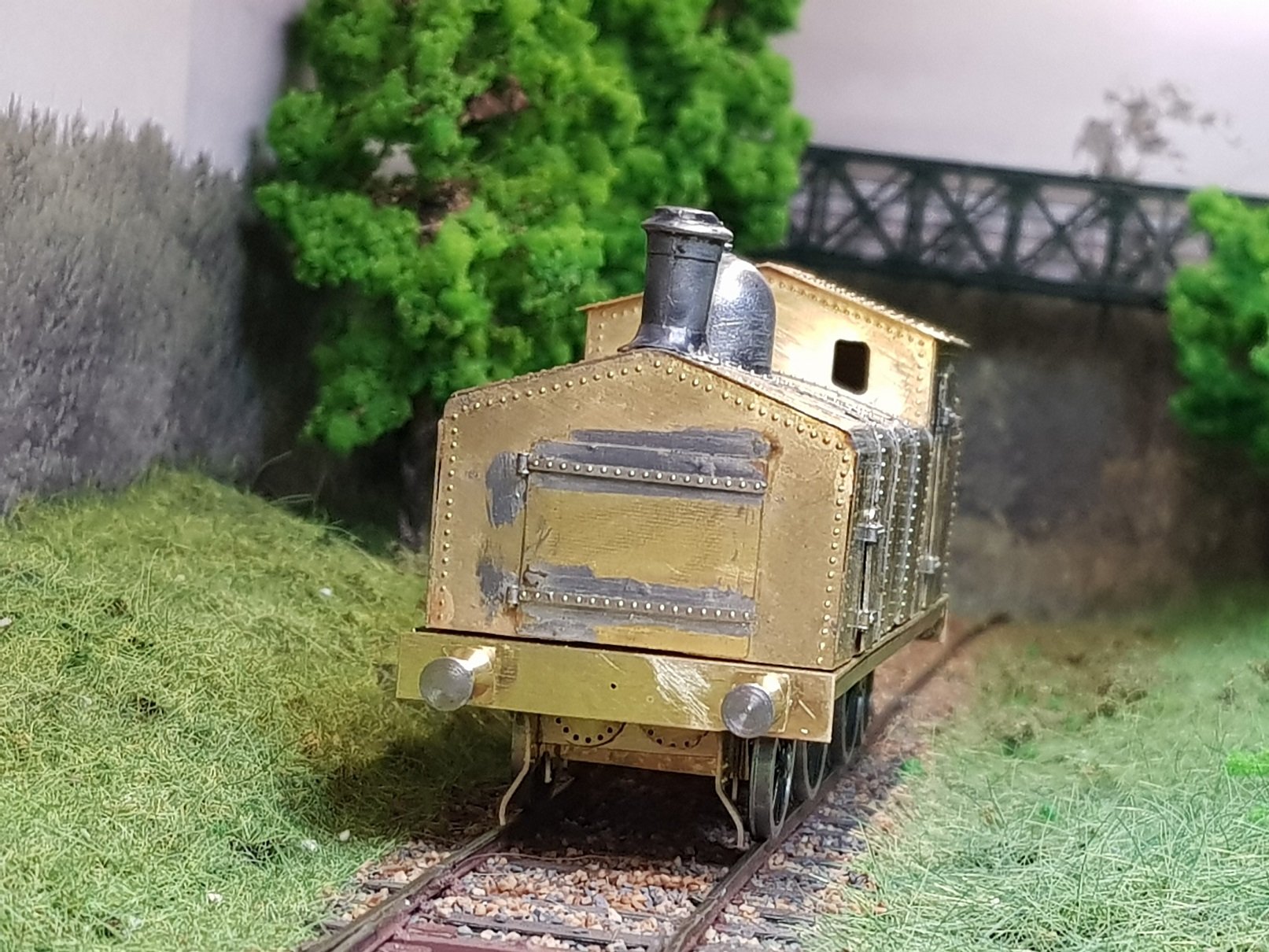
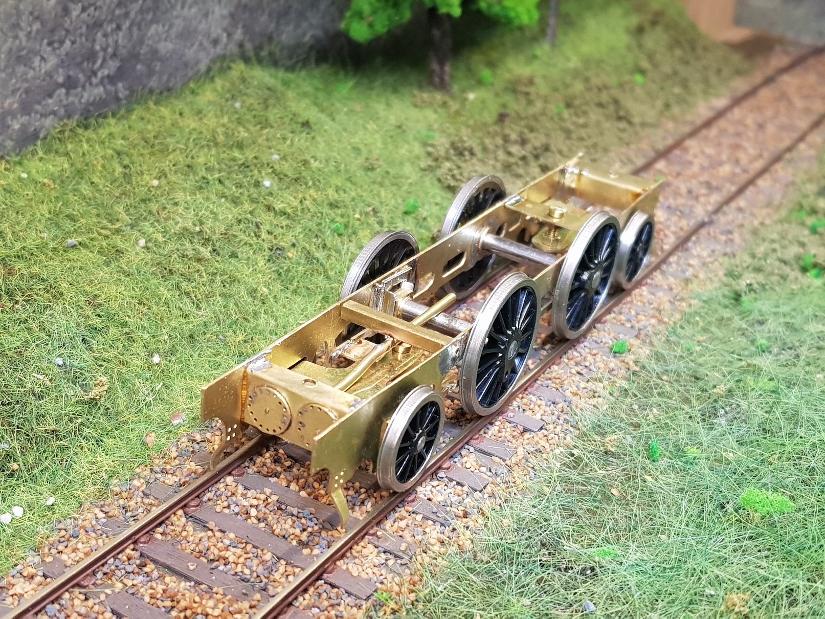
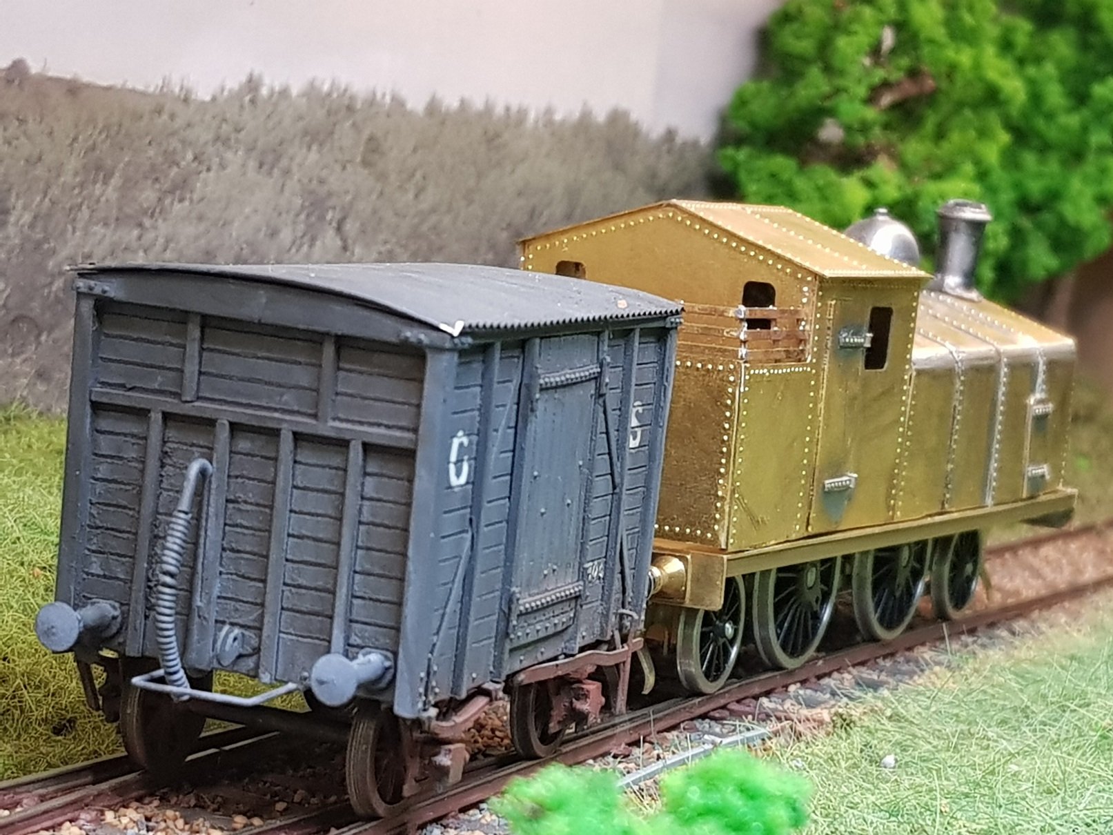
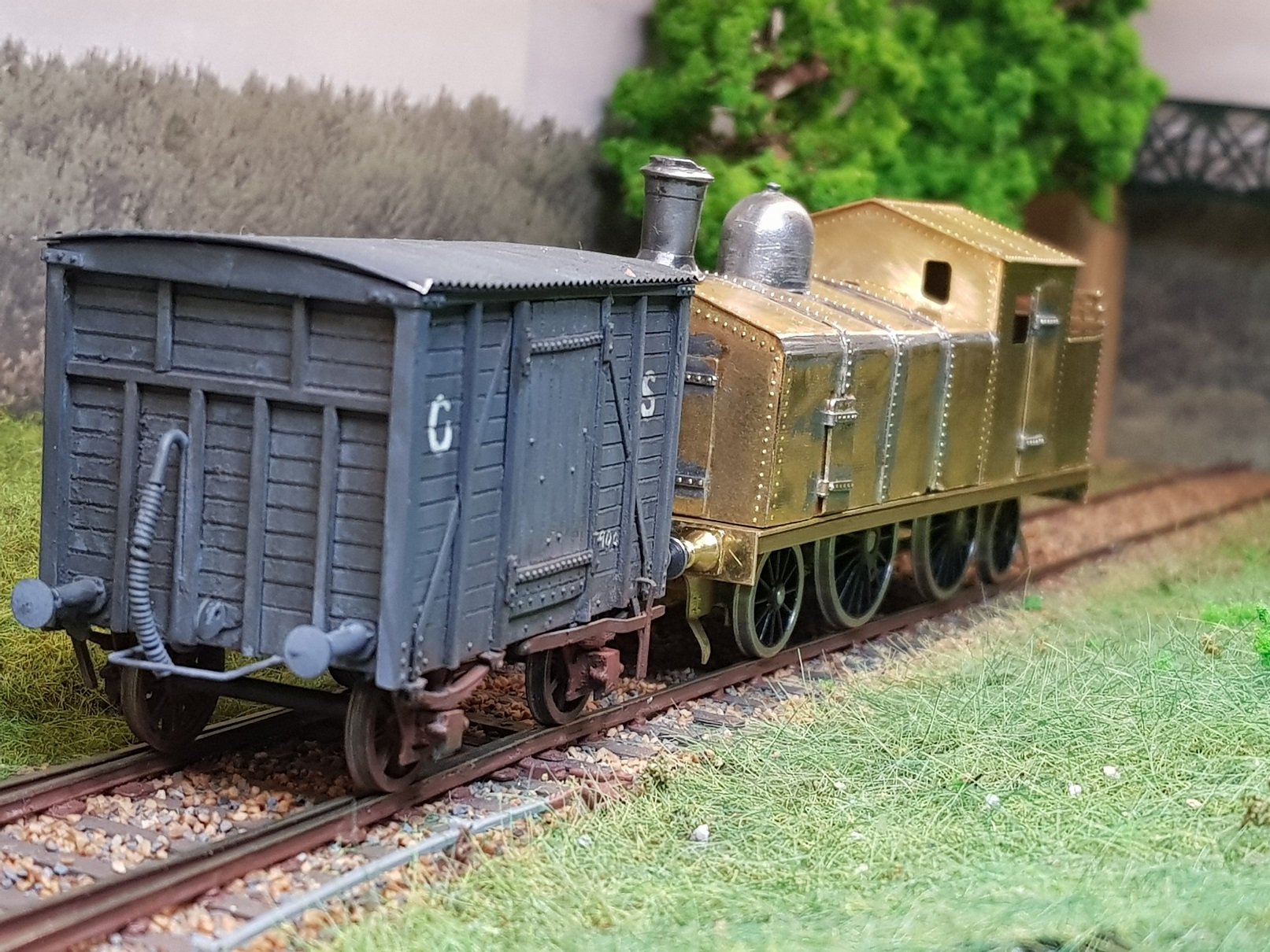
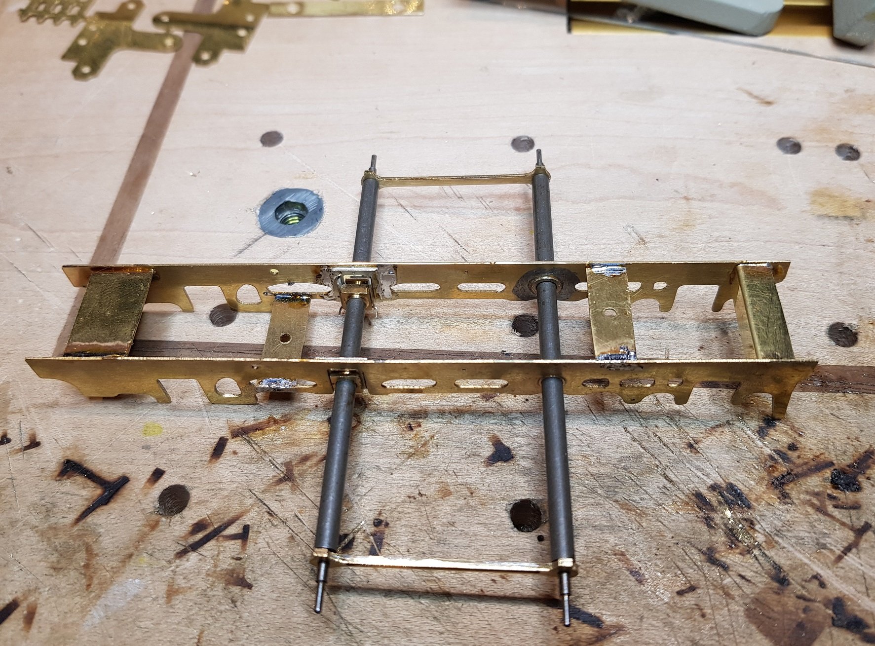
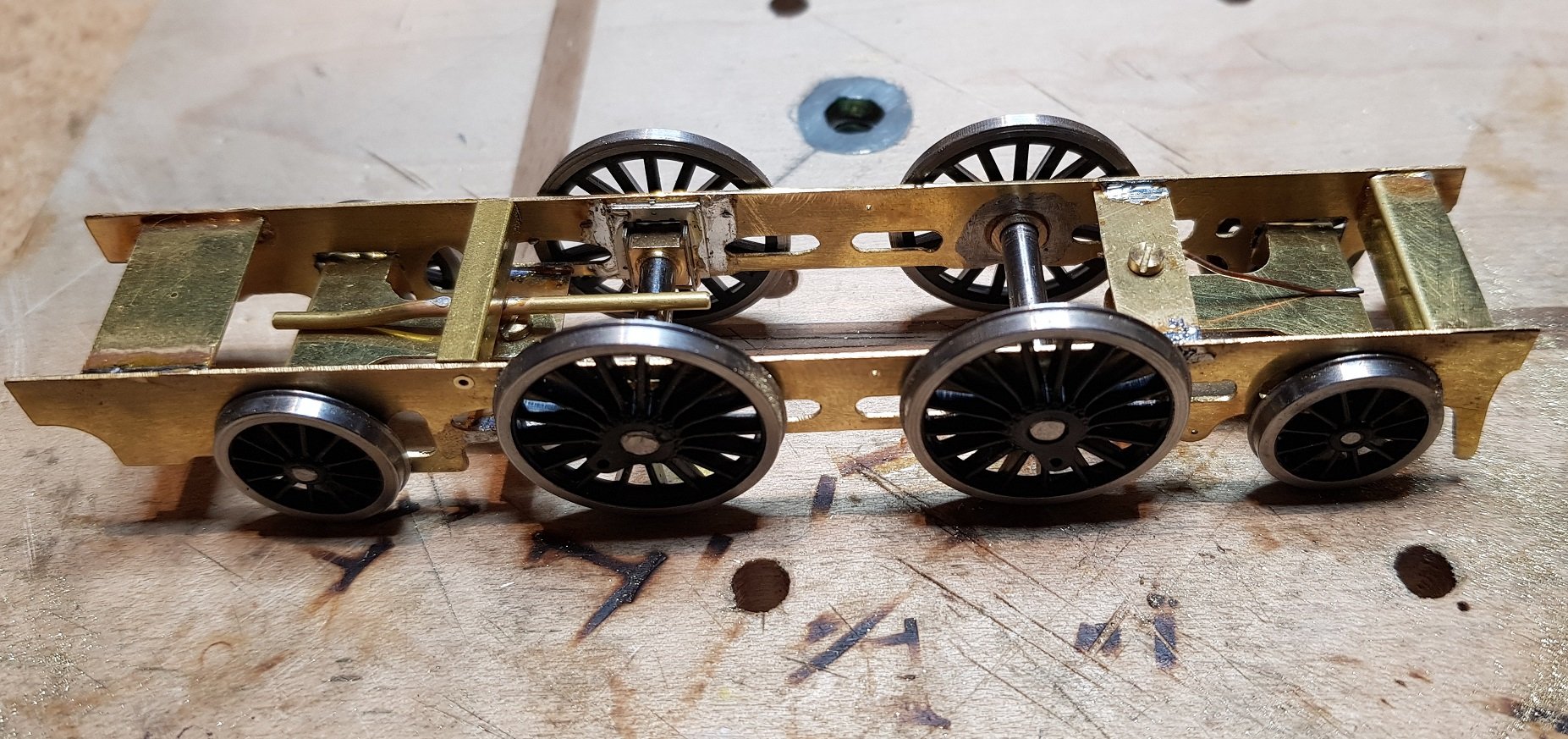
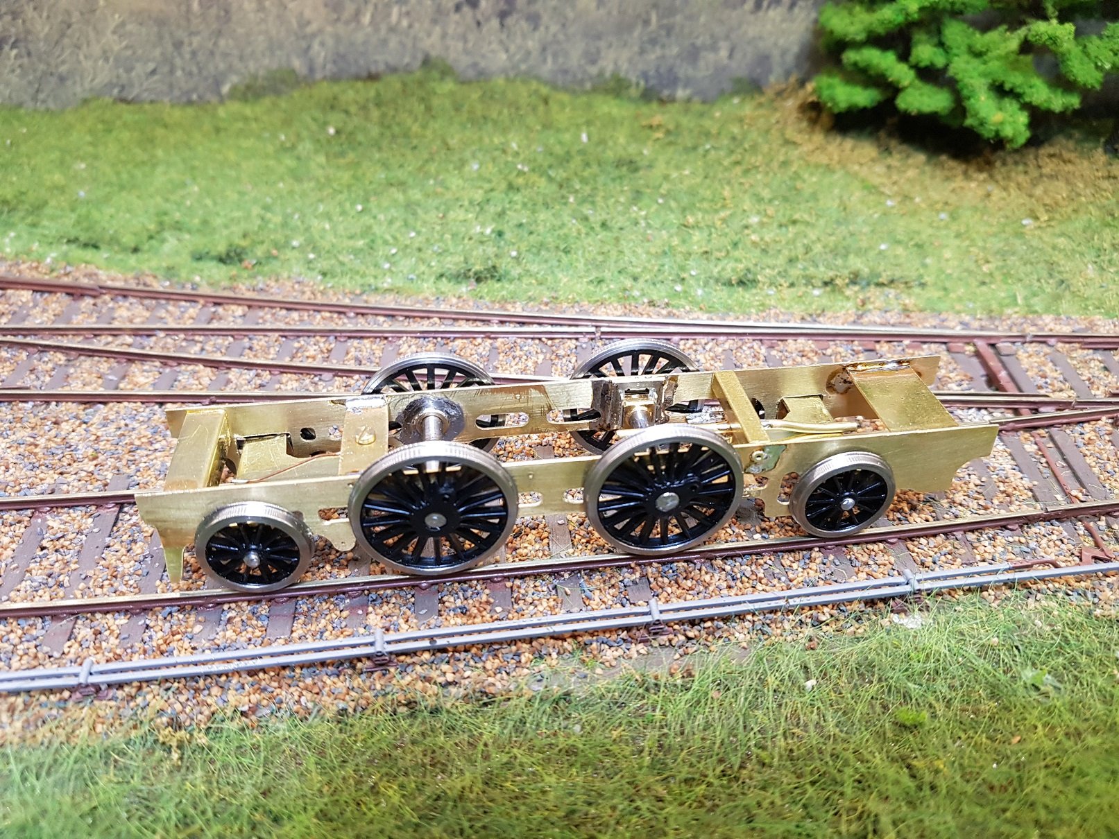
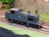
As noted in my last post the chassis was a bit tight for the pony and trailing bogies, so a revised chassis was designed and cut. I felt the trailing bogie was too far back, so this was also adjusted to accommodate - adding a little to the rear & taking a bit from the front to balance. A combined 1mm set was introduced into the chassis (0.5mm per side) to allow the bogies move a little more - the grooves aiding the set points. While I was at it, I decided to add some detail such as cylinder head details, which is lost on the model, but hey, what the hell... The set is just visible which is good, as I didn't want it to be too obvious. Chassis runs through points & curves much better now and with washers on the main axles keeps the chassis straight & should reduce any sparks!! Footplate was built up with angle, buffer beams added, and some nice Slaters GWR sprung buffers which are nicely tapered and a good match for the original. Body fixing points need a little fettling to get get the body to sit down properly. Chimney is just siting on and a bit wonky, but that will be sorted. Cylinder detail is just barely visible, but does look good I think. Couple of quick shots with the covered wagon which it ran with to set the scene! I think the body needs some stiffining as there are some wavy lines which I'm not entirely hapy with. I think the 0.35mm is a bit light - the other loco bodies I have built have been 0.5mm and sit that bit straighter. I'm open to comments from others here who have more experience in the 0.35mm to give some insight. Some more work on the chassis needed; add the crankpins & con rods, motor, gearbox and pickups needed to get it running. Brakes & steps needed to finish it off, but getting there. Ken
-
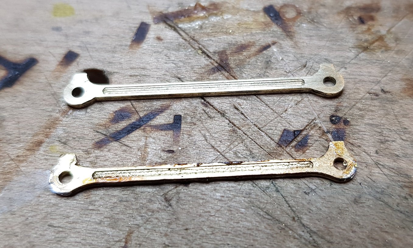
Progress on the Chassis. Con rods were cut out and sweated together. Top complete - bottom needs tidying up. Chassis was assembled using con rods to set bearing distances. Pony & Trailing truck assembled, axles cut and wheels on. Compensated beam for front axles, while traling truck is stablised by some 0.5mm PB wire. Chassis on track and seems to perform well. However. there is very little space for movement by the trucks and I'm thinking there may be shorts where the leading & trailing wheels touch the chassis. A small set in the chassis may provide a little more clearance. I'll monitor this when I put on the pickups. Quick shot with the body on get to a feel for the overall look. Starting to come together. Ken
-
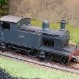
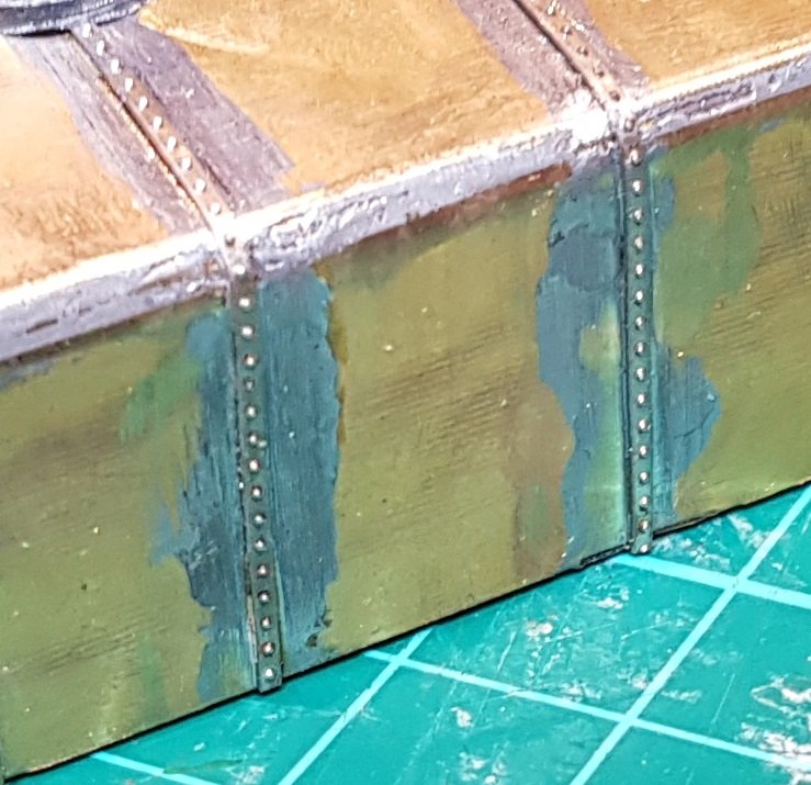
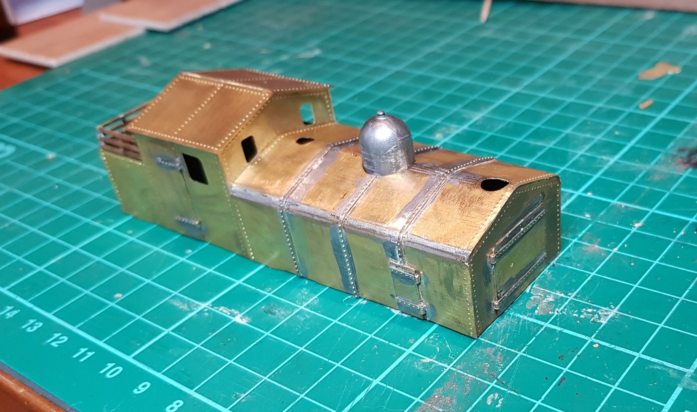
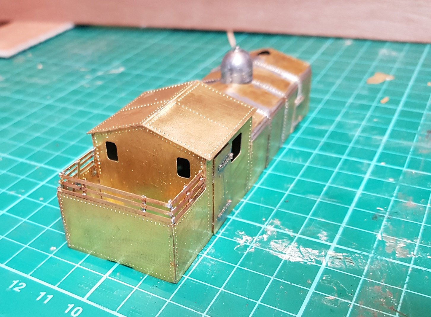
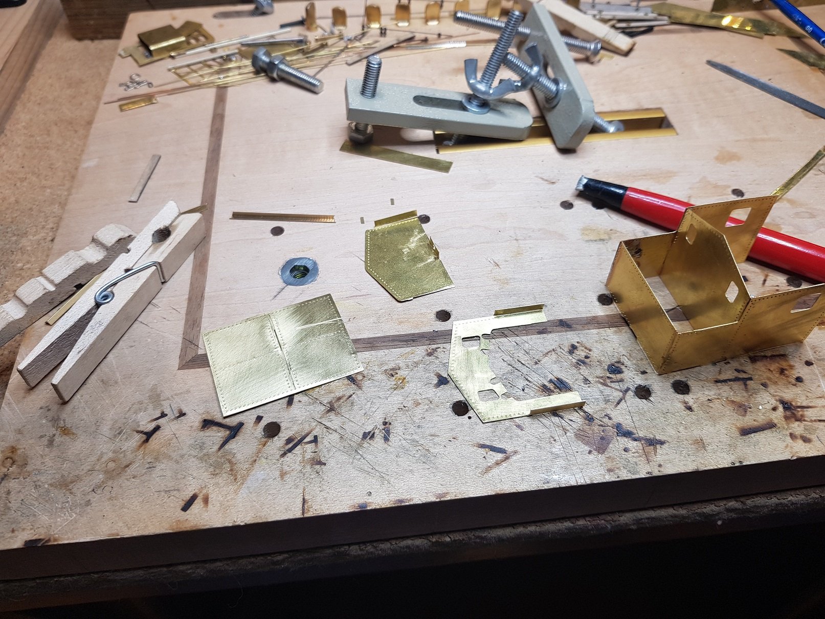
Time to come back to the workbench after some work on the layout. Our good friends Shepherd & Beesley also had a rather nice photo in their book of the DSER armoured train from 1923. The loco was based on thier 2-4-2T, a wagon for troops front & rear, based on the 13"6" Covered wagon, and a flat wagon again front and rear. Image courtesy of Shepherd & Beesley There is some really good info on the Railway protection repair and maintenance corps which goes through the history of measures taken to protect the network here which has some really good photos on the armoured trains, including this one. Anyway - to the Model: I had a drawing for the 2-4-2T, and so by using the chassis and dveloping a bodyshell, I was able to create a cut file for the CNC. Body is in 0.35, which I feel is probably a little light and needs stiffening. The cut files included tabs to provide some stiffening and eases soldering, however I'm not convinced it's enough. I started with the cab area. Grooves on the tabs were a little too deep, so some broke away cleanly and others cut all the way through, but held at each end ( I can already see Eoin shaking his head slowly & sighing ) I'll get that sorted for the next cutting project! I didn't take may photos as I was building, as I tend to get focused on what I'm doing and forget. So photos of the nearly completed body. A chimney and piece of brass pipe for the safety valves is all that's needed to complete the body. It's rather simple construction, and given the simple slab sided body, riveting detail is really needed to provide some level of visual interest. Chasssi was cut out from 0.5mm and is in the process of tidying up ready for assembly. All for now. More as time permits. Ken
-
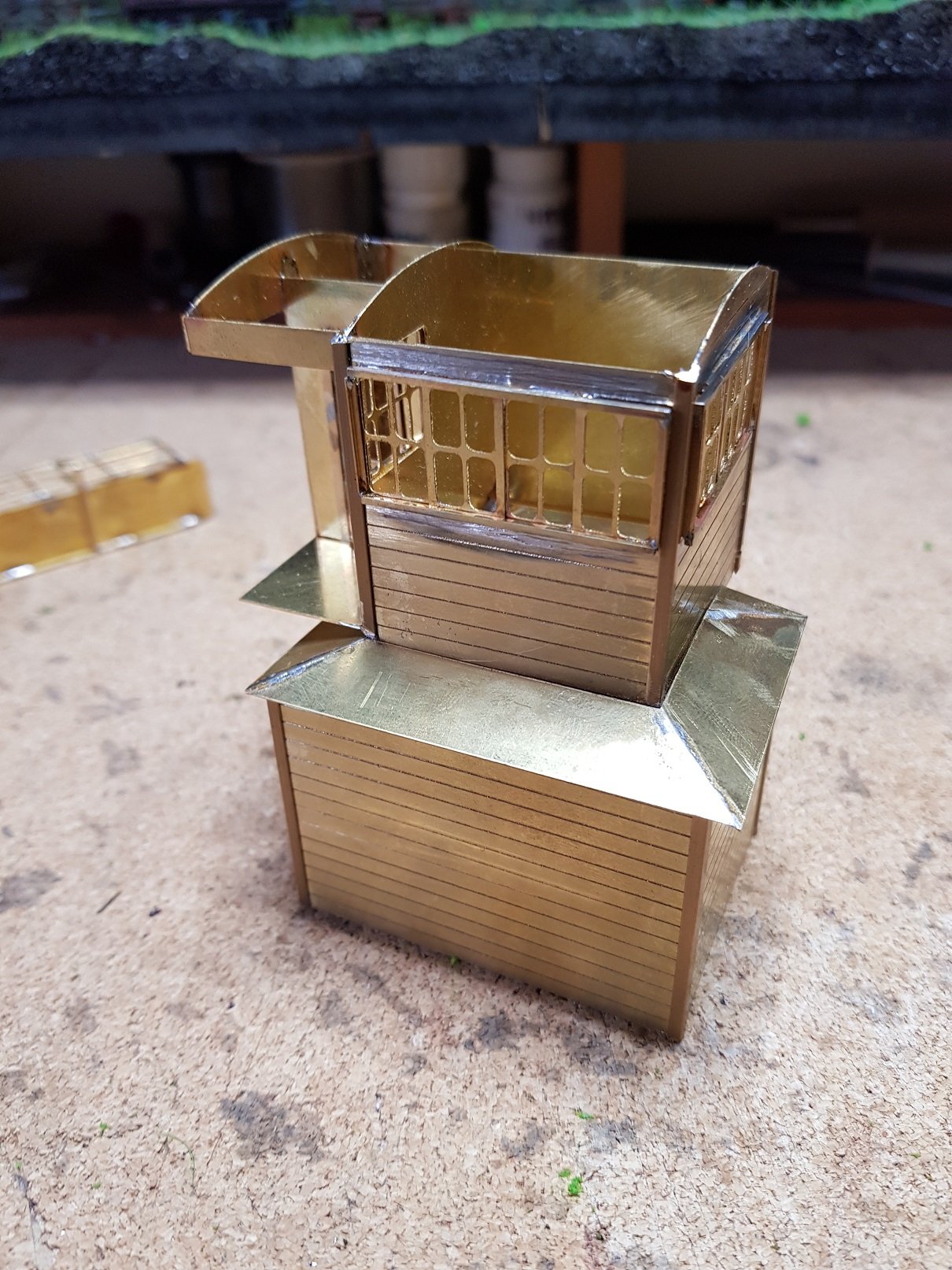
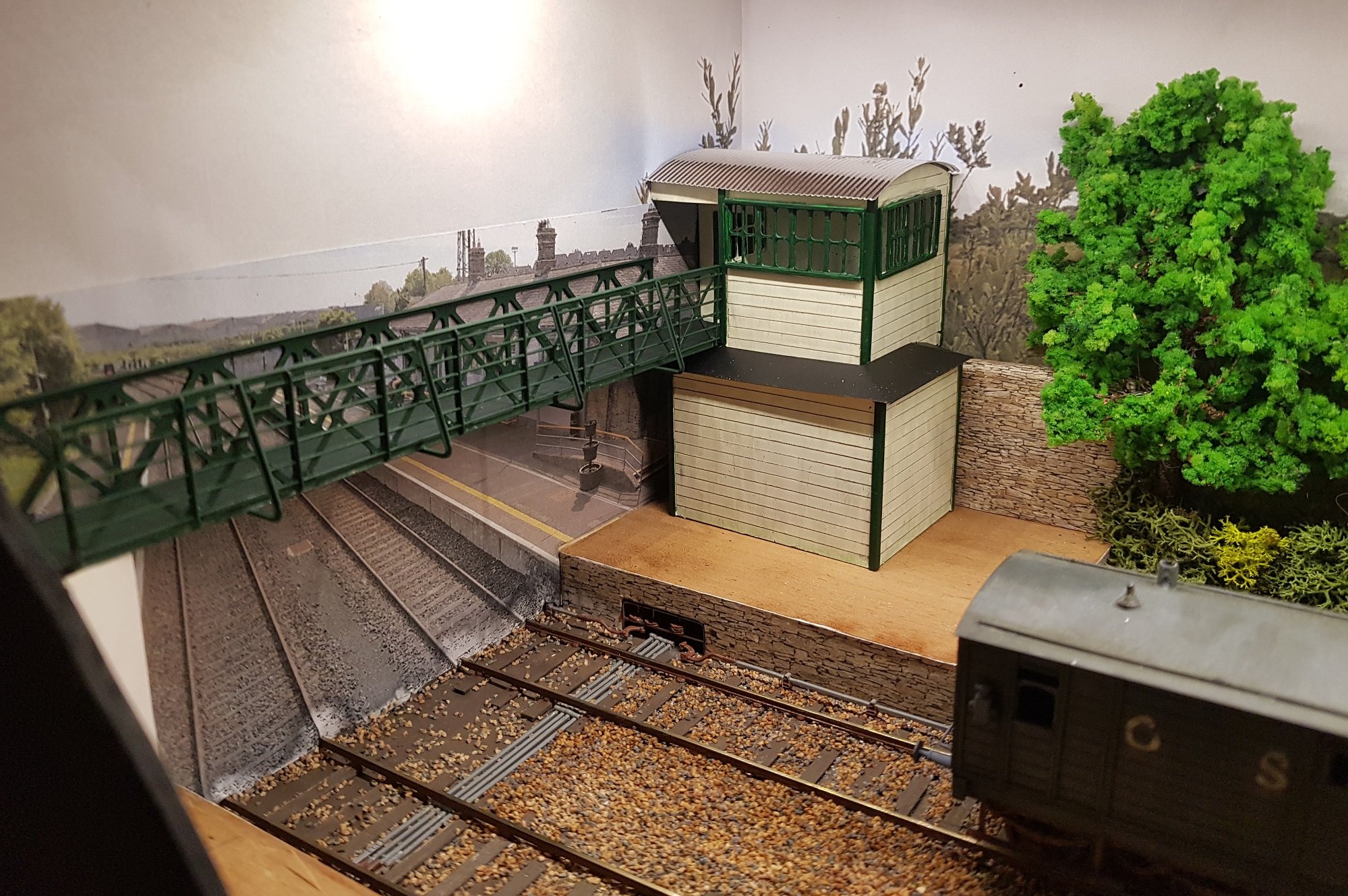
Ok - given the change in roof profile, I decided to redo the signal cabin. Bit of CAD, bit of Brass, run on the mill & some soldering, we get..... Add a bit of paint & some light wash, we get this...... Bridges got a lick of paint as well - weathering needed there to tone them down a bit. Roof of the signal cabin needs to be painted, but the silver finish doesn't look too bad. Lower roof needs to be dressed also to take away the flat primer finish. Getting there. Ken
-
Very nice details there, Tony. This layout has really matured into a show piece. I really like the small details such as the spare crossing vee in the yard, etc. Well done. Ken
-
Looking good David. Getting the right finish to the ballast / ash / clinker is more difficult that it first appears, however once done really finishes a layout! I have a lot to do with my layout to settle the ballast down, but your comments above give some good ideas. Ken
-
Hmmm.......If this is correct, I may need to change the detail, as my modelling era is 20's to 40's. I have some photos of the signal boxes further down the line which I can use to modify the model. Thanks Guys - this info is much appreciated and helps with accuracy. I'm getting very used to the track guage - it just looks right, although not without its challenges. Ken
-
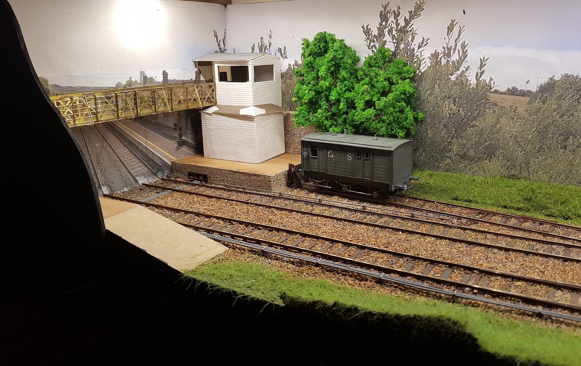
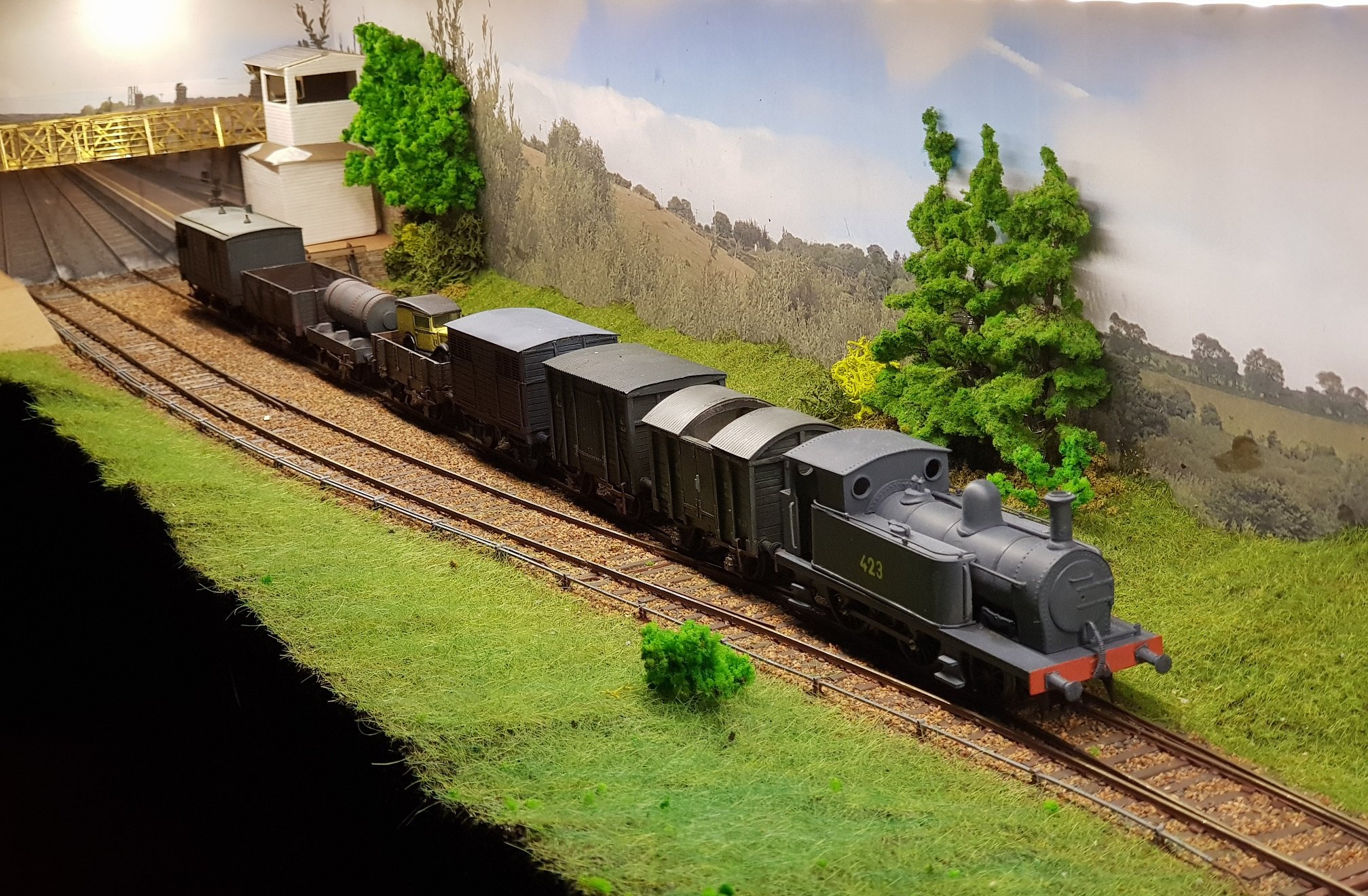
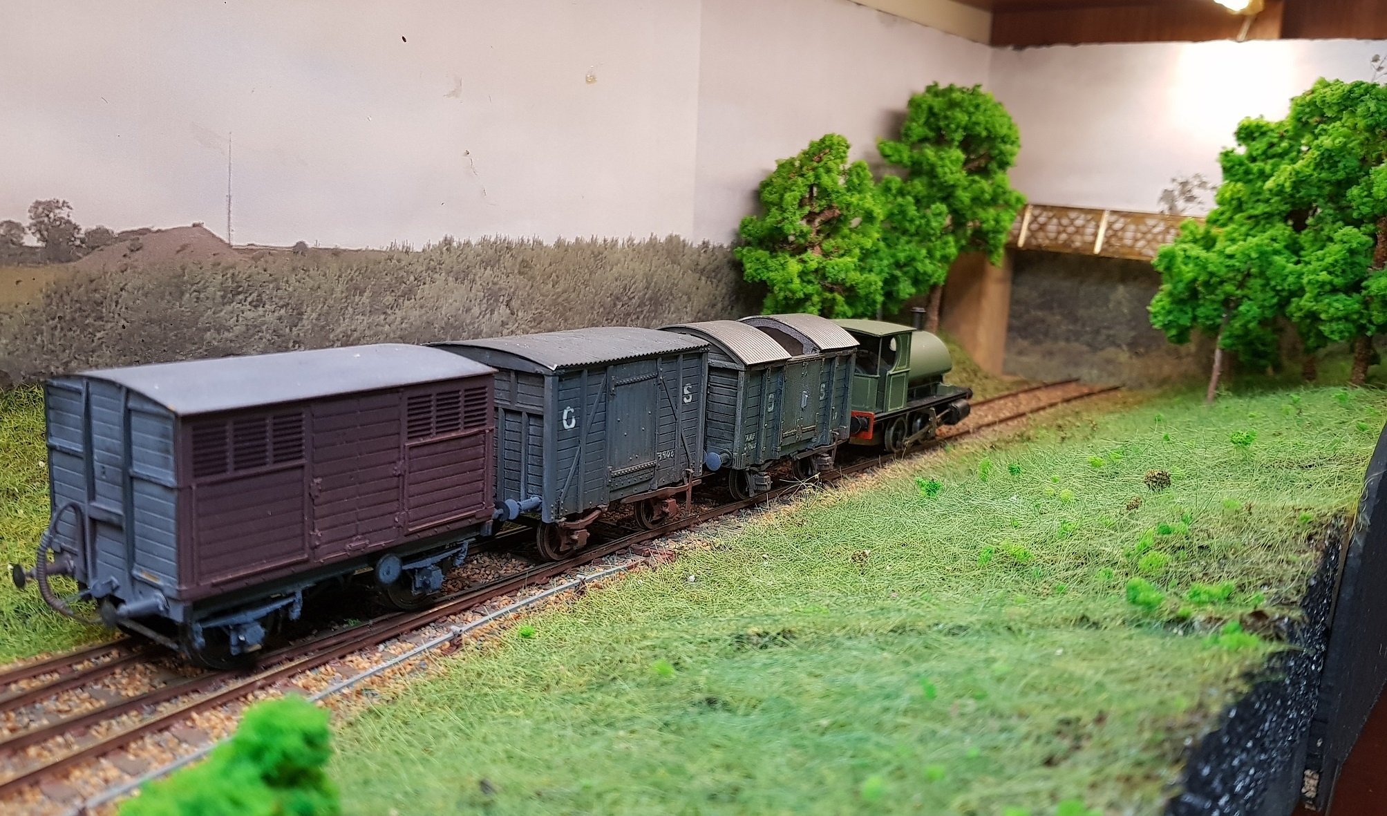
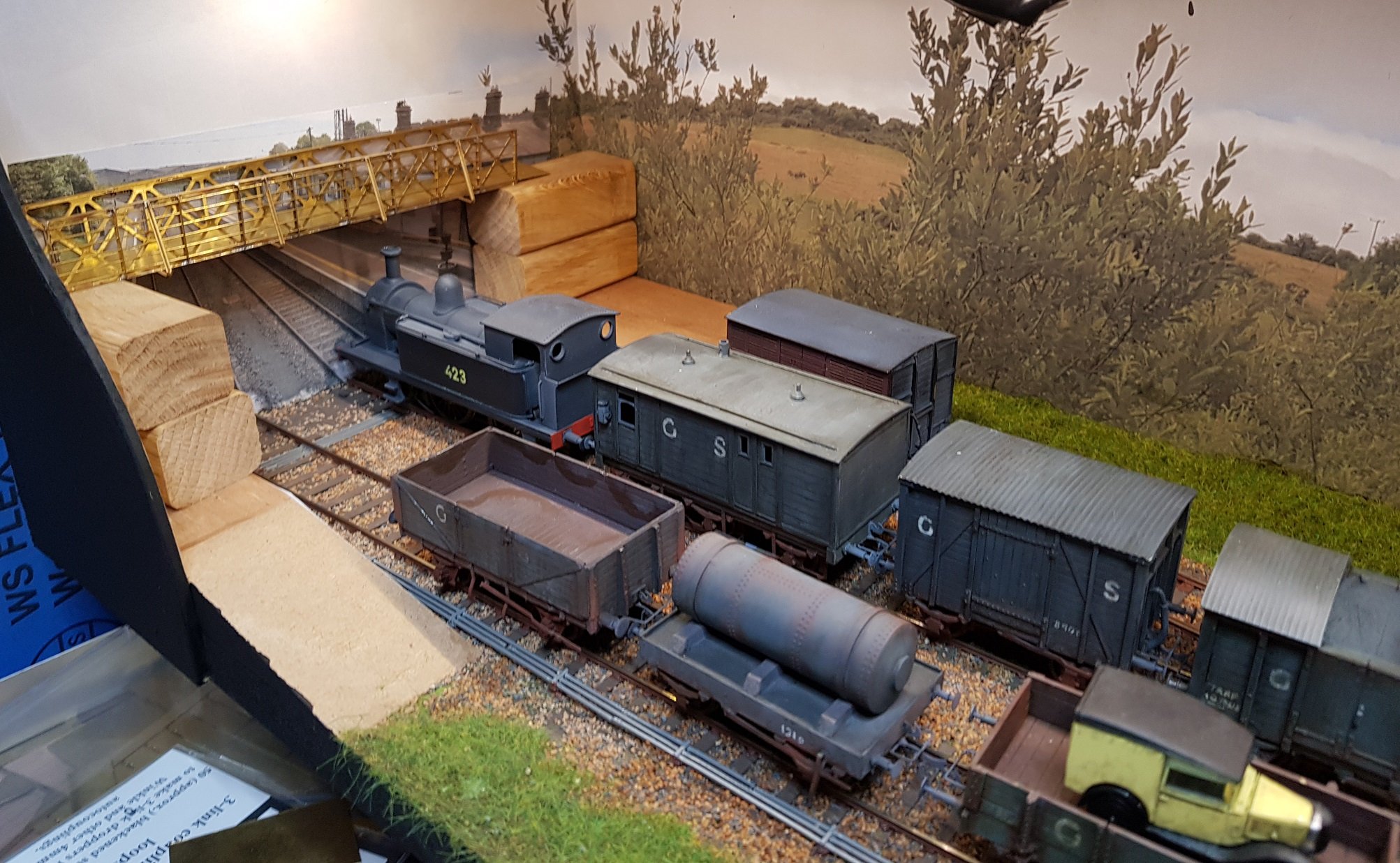
Was doodling with the signal box earlier, but there is still a lot of work needed. Windows have been made up in brass & will need paiinting before fitting. Corner trims will also be needed to finish the look. Nothing has been done on the platforms, but that will probably follow fixing the signal box in place. That way platform fiinsh will dress into the building without seam lines. Got a little work done over the weekend; not much, but getting some trees in is starting to help the barren look. Footbridge piers to be made to dress the bridge & scenery together. I may open that end to allow for a sliding fiddle yard for display purposes. Looking back to the station with 495 & the goods wagons. 423 with a goods train to set the scene. A lot more scenery needed to blend the foreground into the backscene. Trees are very bright green and will need toning down to look a little more realistic. Coming together nicely though! More as time permits Ken
-
Hello All, Would anyone know what colour station trim such as windows, doors, facia / soffits, bridge & railing ironwork, etc would be? Any thoughts? Ken
-
Lovely looking model and the valve gear looks great. Flange depth on wheels is rather deep though. How is it driven - I don't see any gears on the loco. Is it tender driven, or by chance is it driven through the valve gear? Ken
-
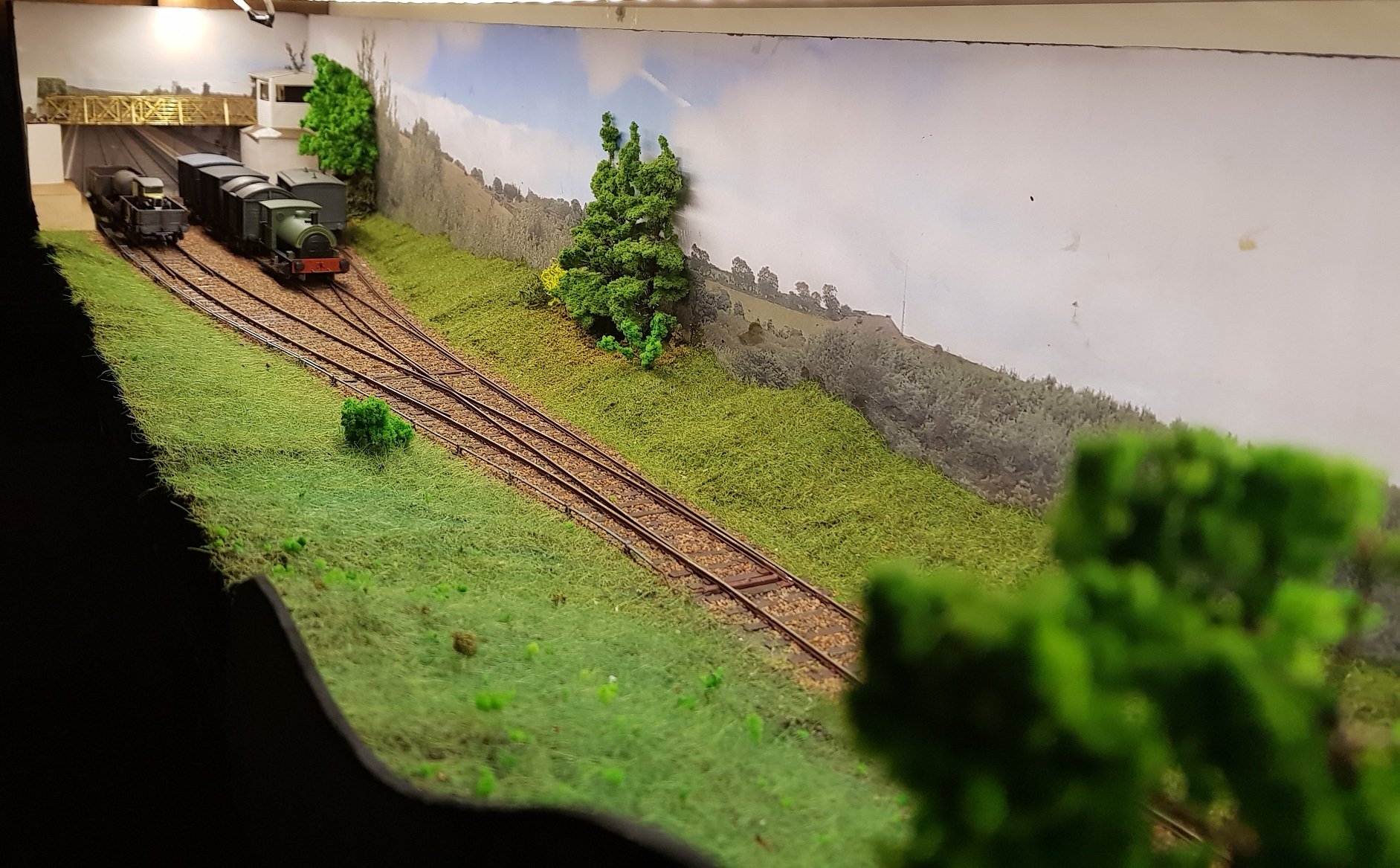
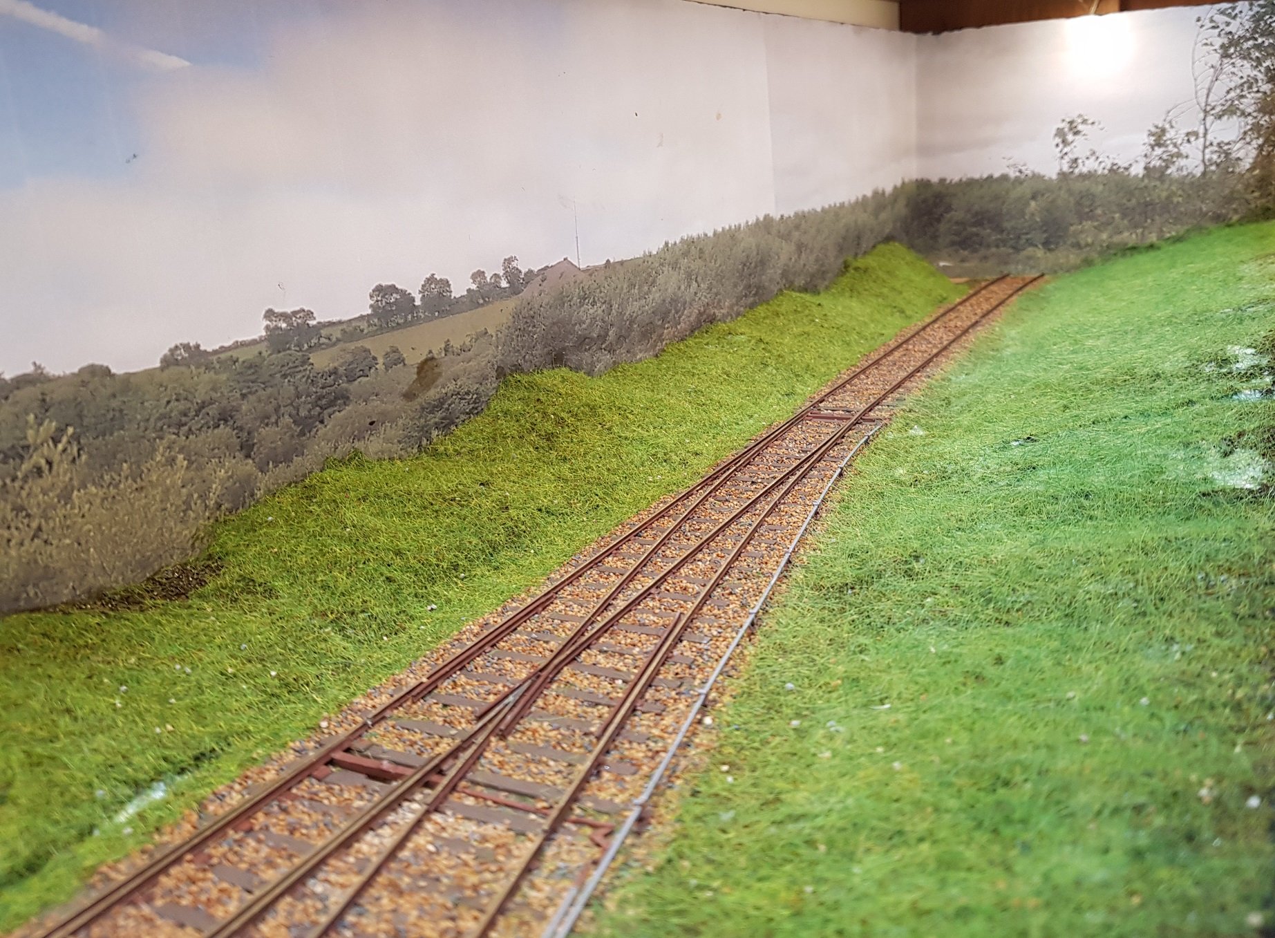
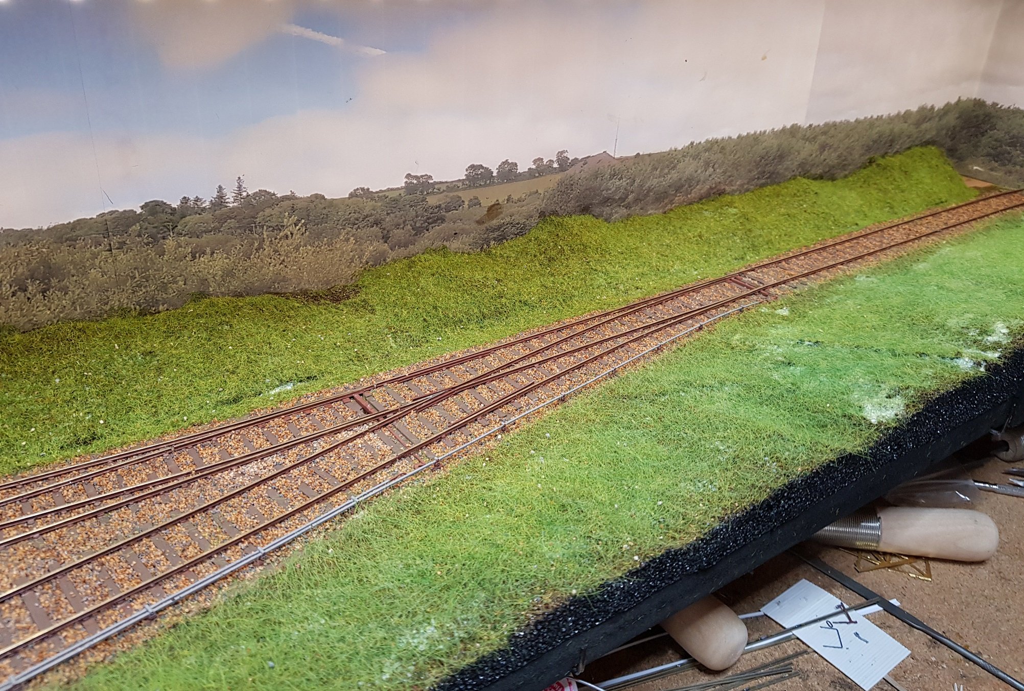
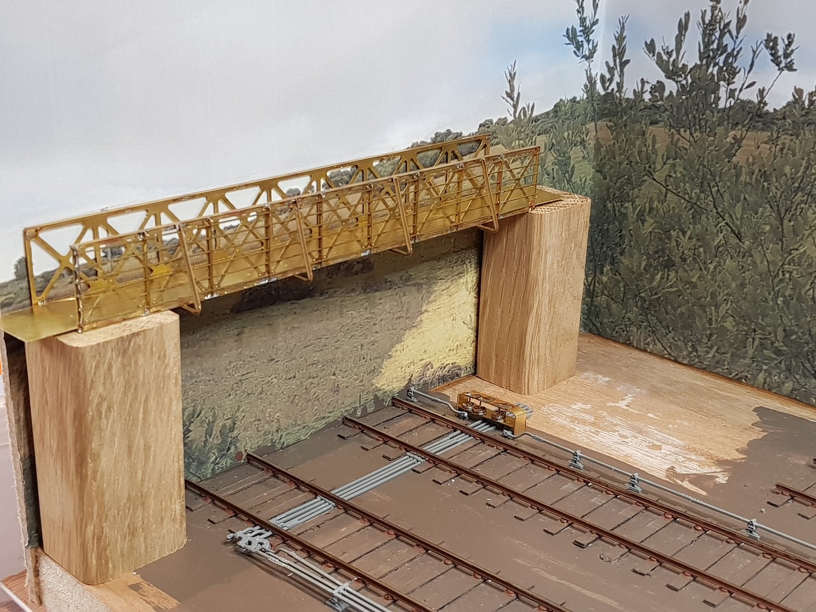
Ok - so a lot later. Work getting in the way of modelling so have only made a little progress. Track has been ballasted, however ti does need some tidying up. Scenery has been cut from packing material - closed cell type plastic material - don't know the name, but it is a spongy material and was cut with a fret saw to give some profiling. Static grass added & glue is still drying, which explains the white undertones. Station bridge just sitting on timber blocks for the moment to get a feel for how the revised station backdrop will look. Gap in the scenery at the end to allow insertion of bridge stone work - the gap can then be dressed into it. Veiw back to the station. View back towards the pedestrian bridge end. Toning & colouring of the grass needed to blend together. Overhead view. Platforms have been added, but apart from stone edging, there is very little work done here. Signal box to be constructed to set the bridge in place, so hopefully can make some headway into this over the coming period. More as time permits. Ken
- 17 replies
-
- 10
-

-
This is certainly an alternative if your up to it?? PS - I recommend you wear welding gauntlets.........
-
Yes, yes.........that's what I'm doing at the moment with my layout - Visualising.........just imagining what it wouild look like, if I ever got a chance to do some work.........
-
Coming from the engineering perspective, I much prefer If it aint broke, it doesn't have enough features!
-
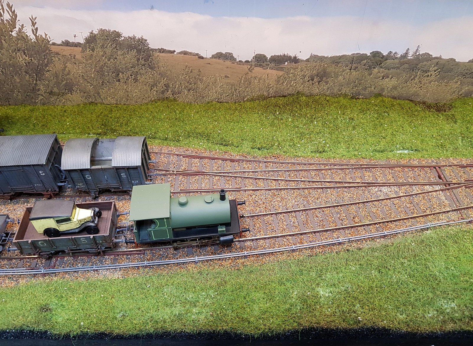
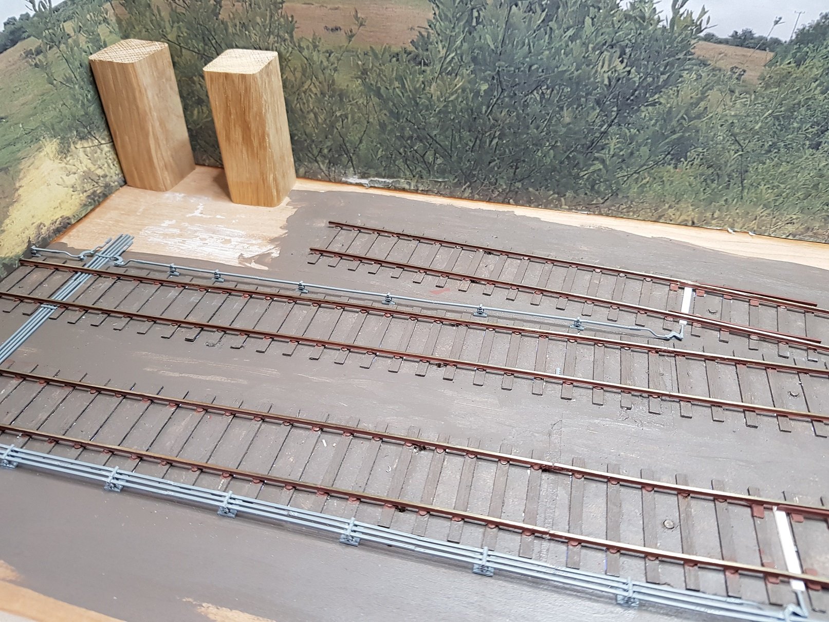
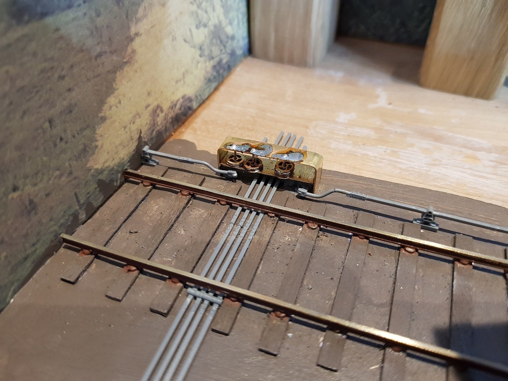
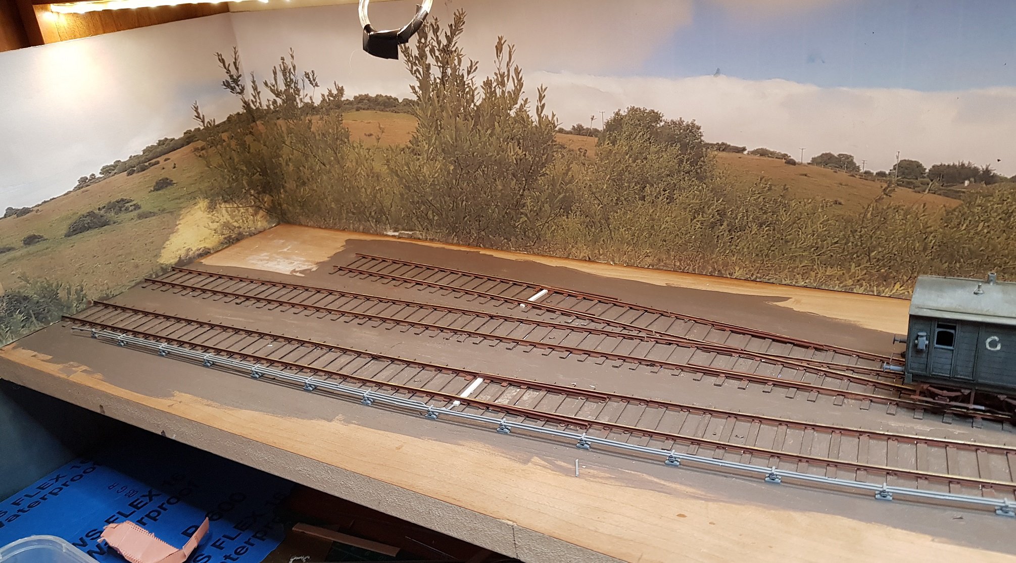
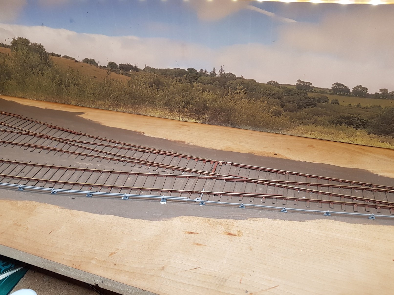
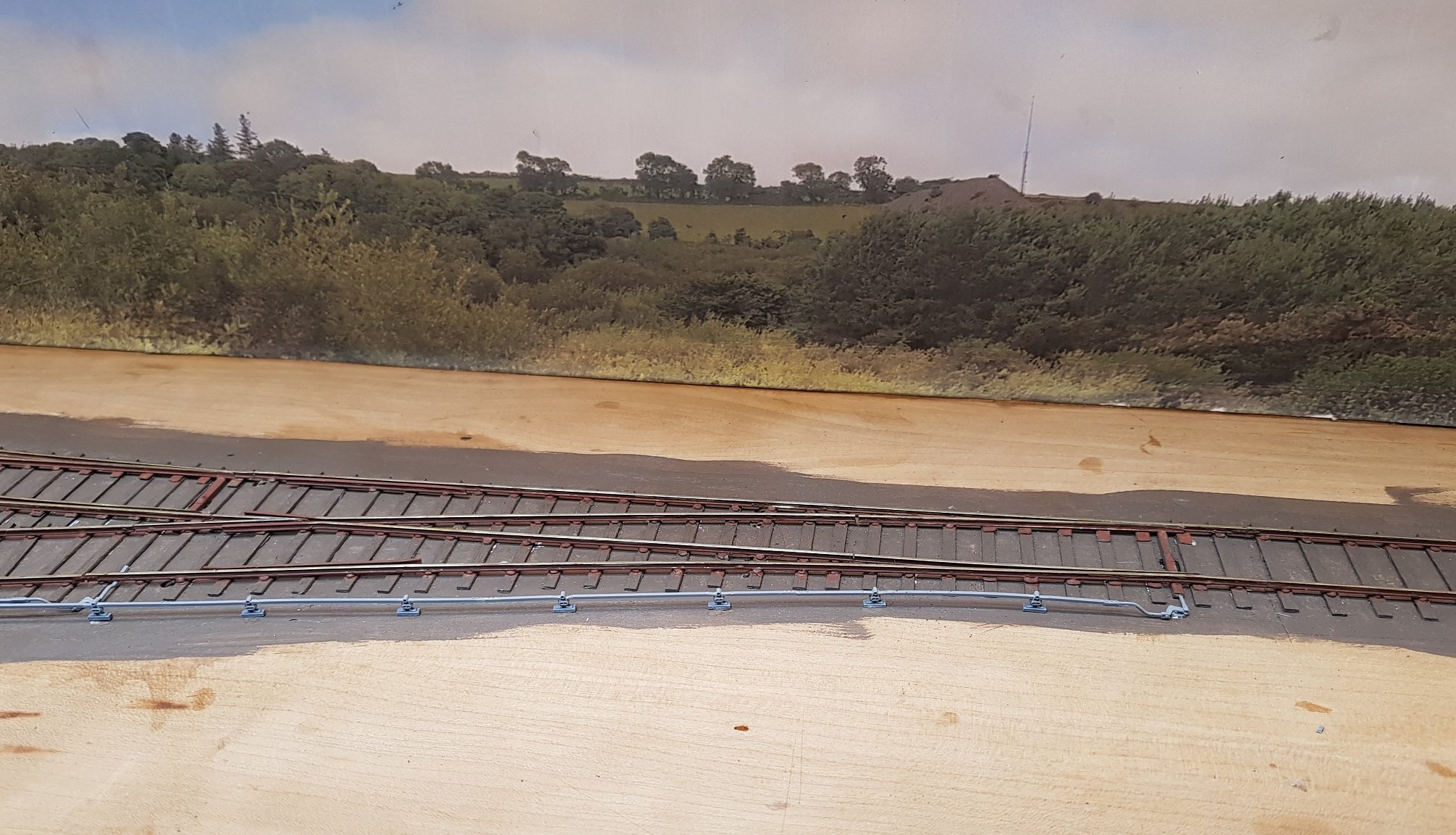
A little more progress on the layout. Think I have the point rodding sorted - albeit after a few "doh" moments; angle cranks the wrong way around! Short siding catch point picked up. All connections brought back to the signal box. Added a few rods and cranks for the points on the North end of the station which adds a little interest. Detail of the rodding back to the platform ope where the signal box will be including the completed platform bridge. Made a start on signal wheels at the signal box end. May leave the signal end until I get some signals installed. Next up will be platforms & then ballasting, Starting to take shape! More later. Ken
-
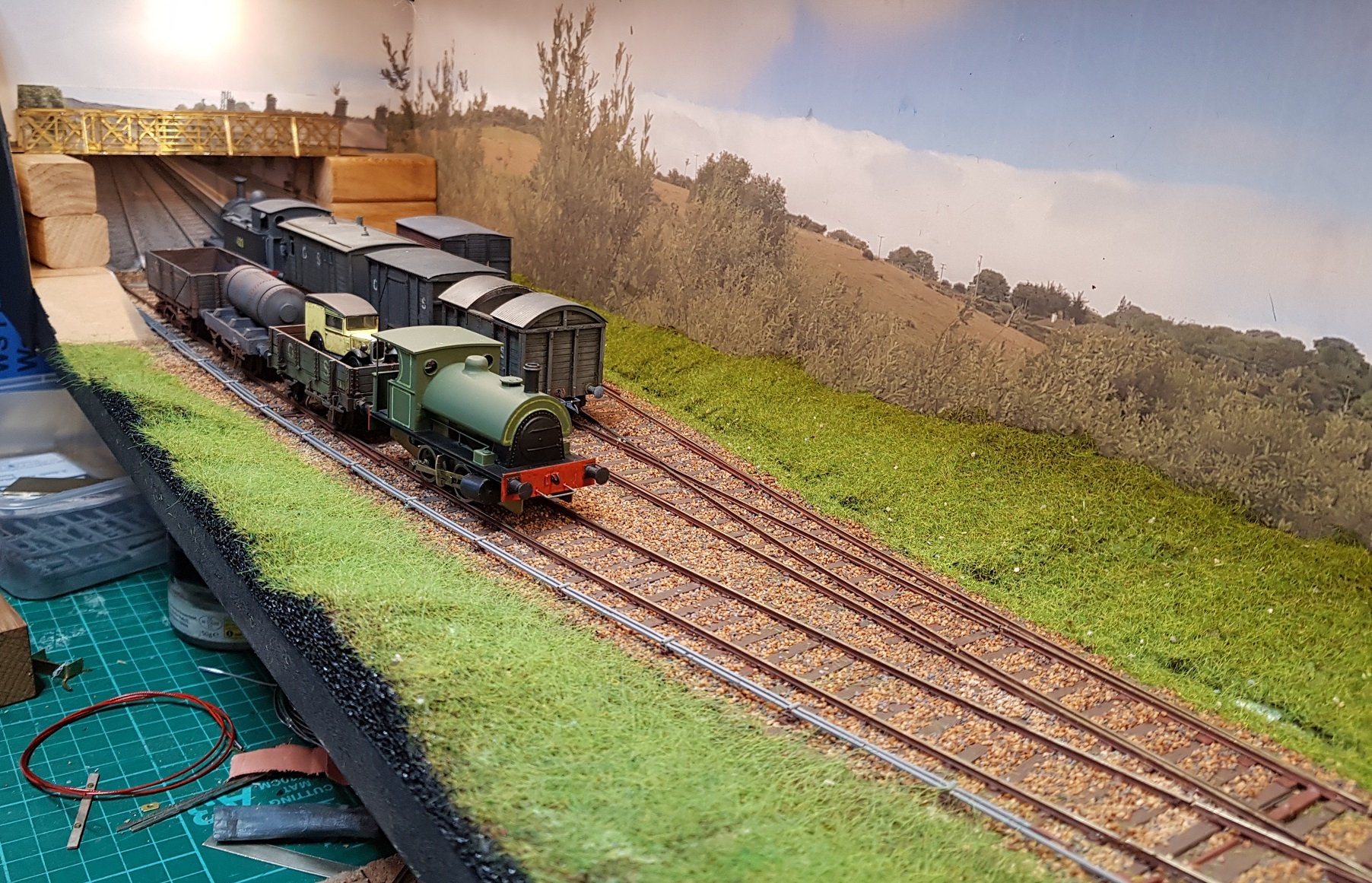
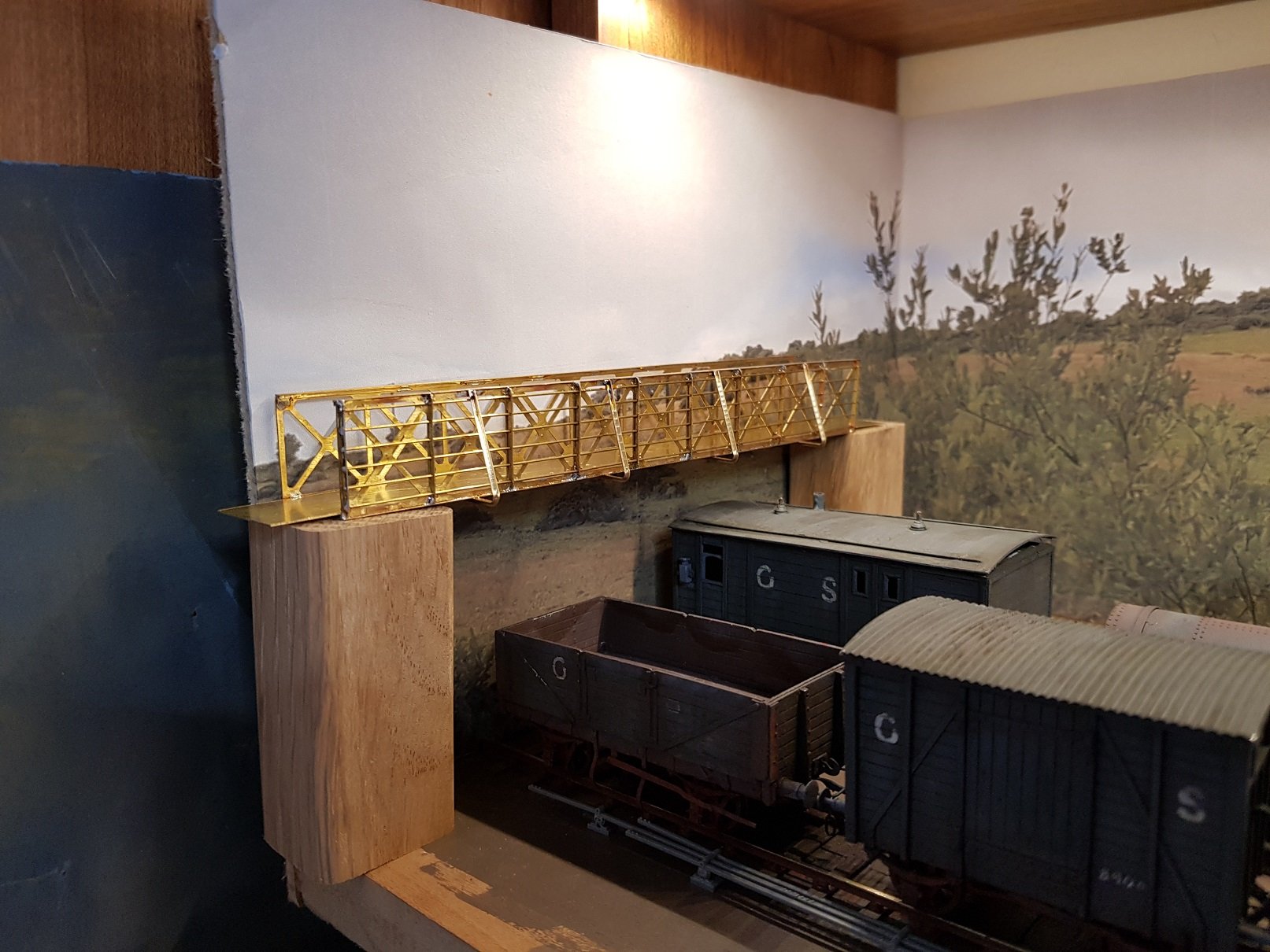
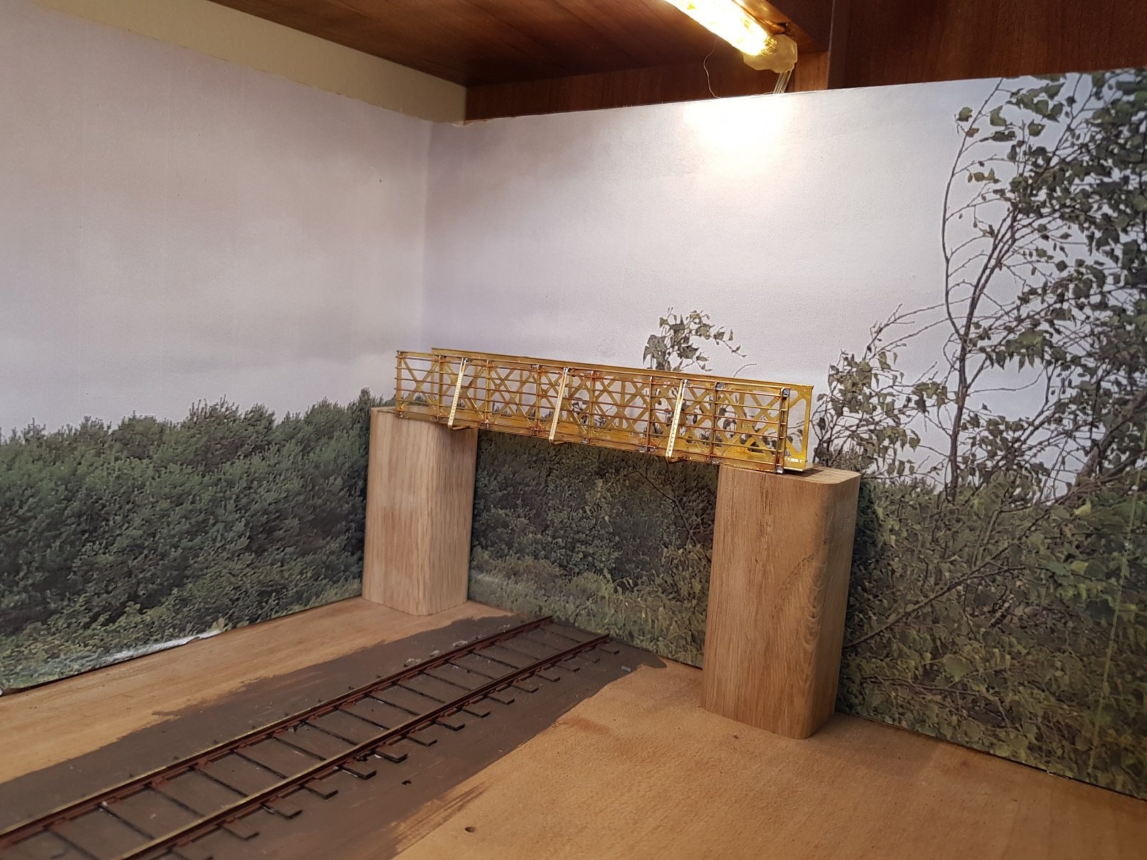
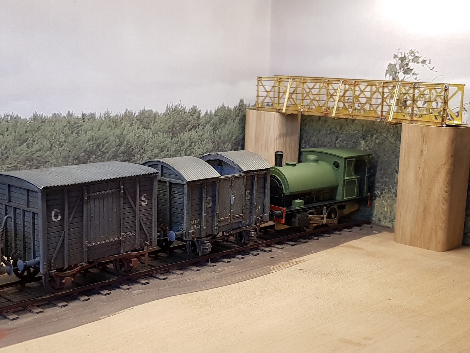
So, Corrected the problem with stopping short with the rods, they now run to the end. A floor added and back section connected. The DSER bridges have an interesting support which runs clear of the underside and then turn up at an angle to the top rail. Adds a nice touch. Trial positioning with some timber blocks for now. I haven't detailed the back cut - a few lines on the backscene will probably suffice. Back scene for this area will be prototype photos (hopefully). Got to work on the footbridge at the other end. This is the same structure as the platform bridge, so I'm not going to go through the construction details. A quick shot with 495 and a few wagons to set the scene!!
- 379 replies
-
- 12
-
-

-
Hello John, I work quite a bit in brass & bought the RP Toolz Photo Etch Bending Tool - see link. https://www.ebay.co.uk/itm/RP-Toolz-18cm-long-Photo-etch-bender-tool-RPT18/192932372777?hash=item2cebaa6129:g:HUcAAOSwNndctxPi For working with etch kits they really are essential - it is possible to do with a vice and steel rules etc, but that can get tedious and not always so accurate. They are pricey but do provide the crisp edges you are looking for, and make the difference in kit building. Hope that helps. Ken
-
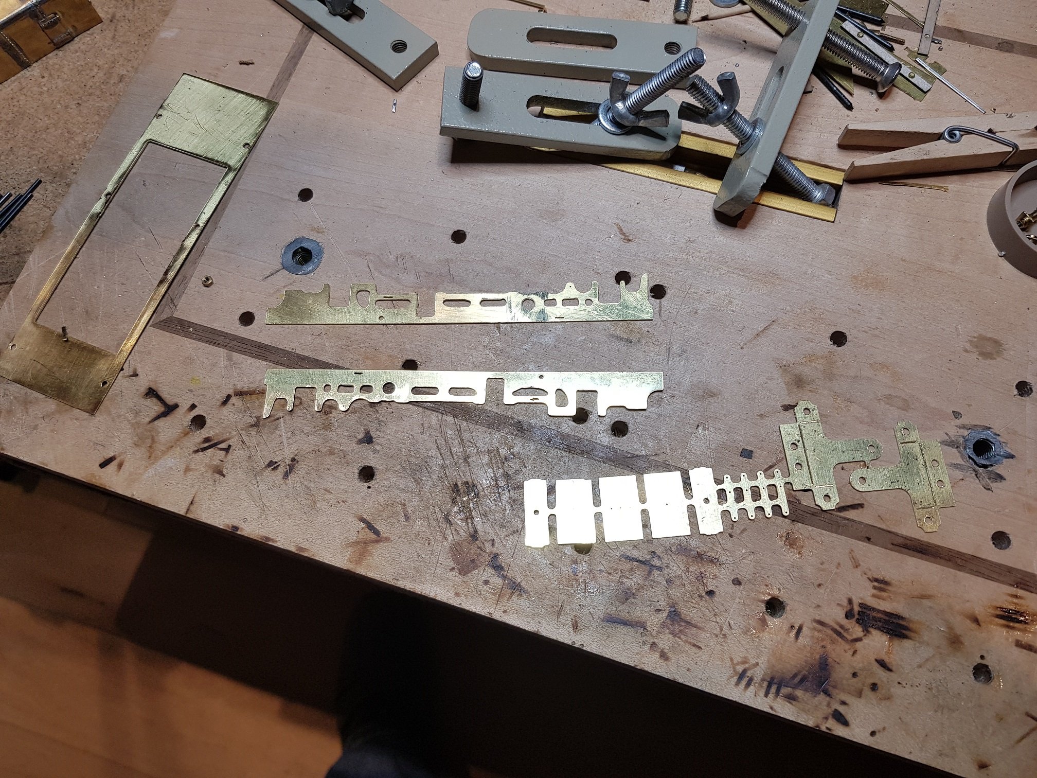
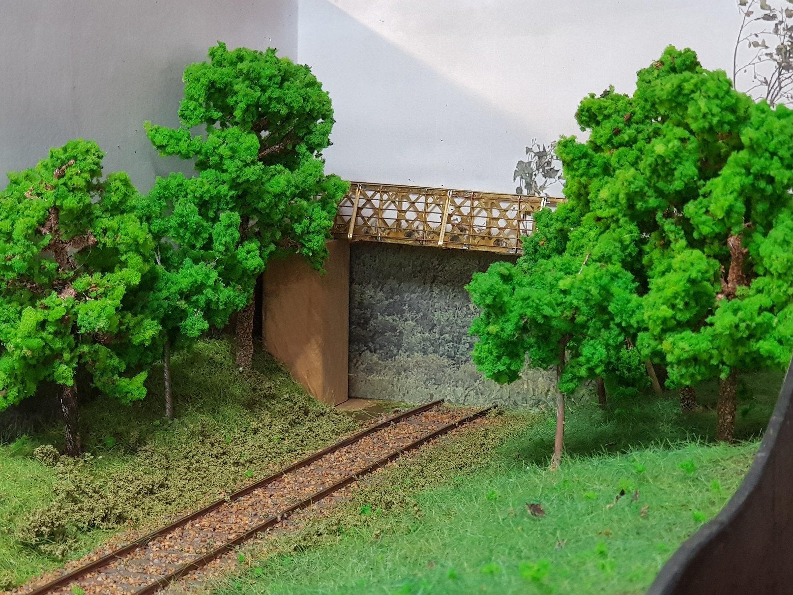
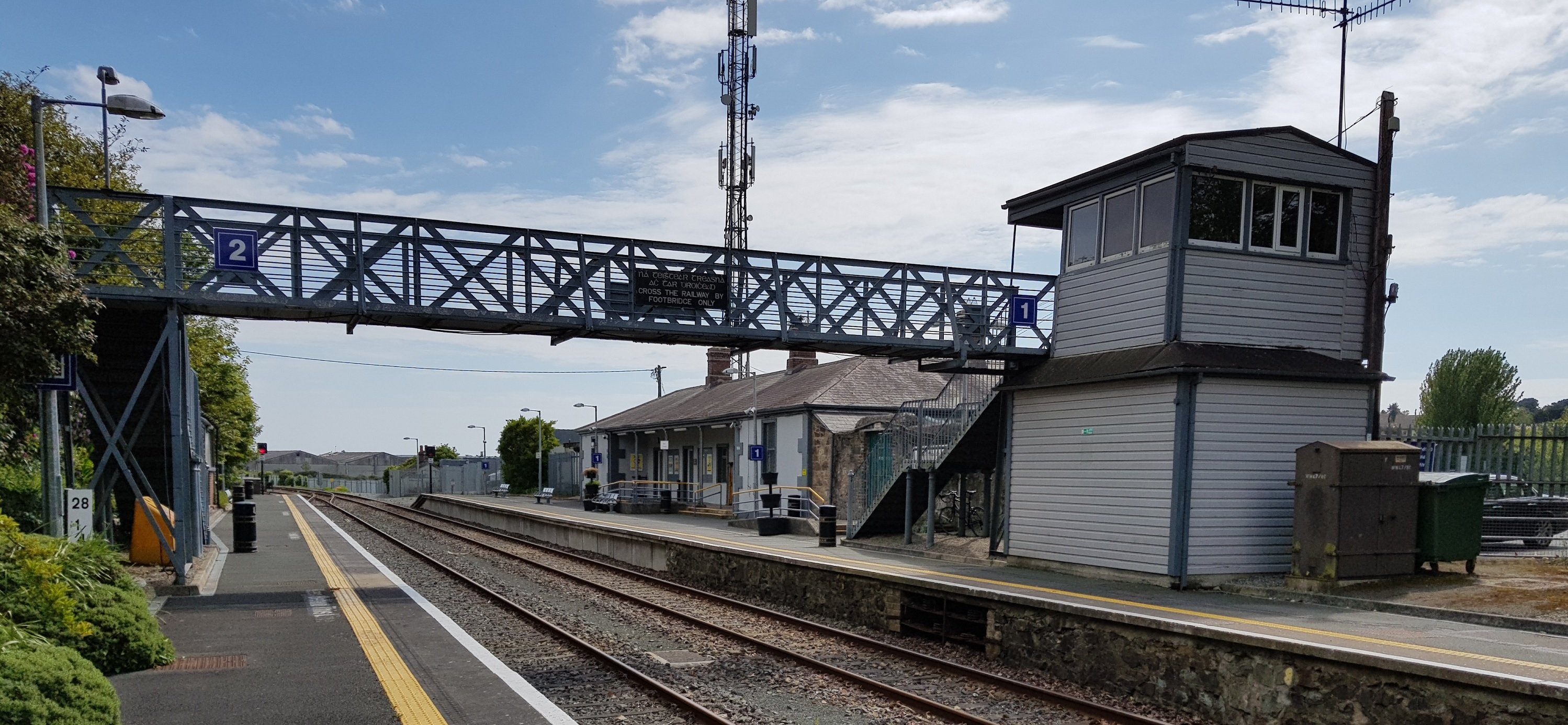
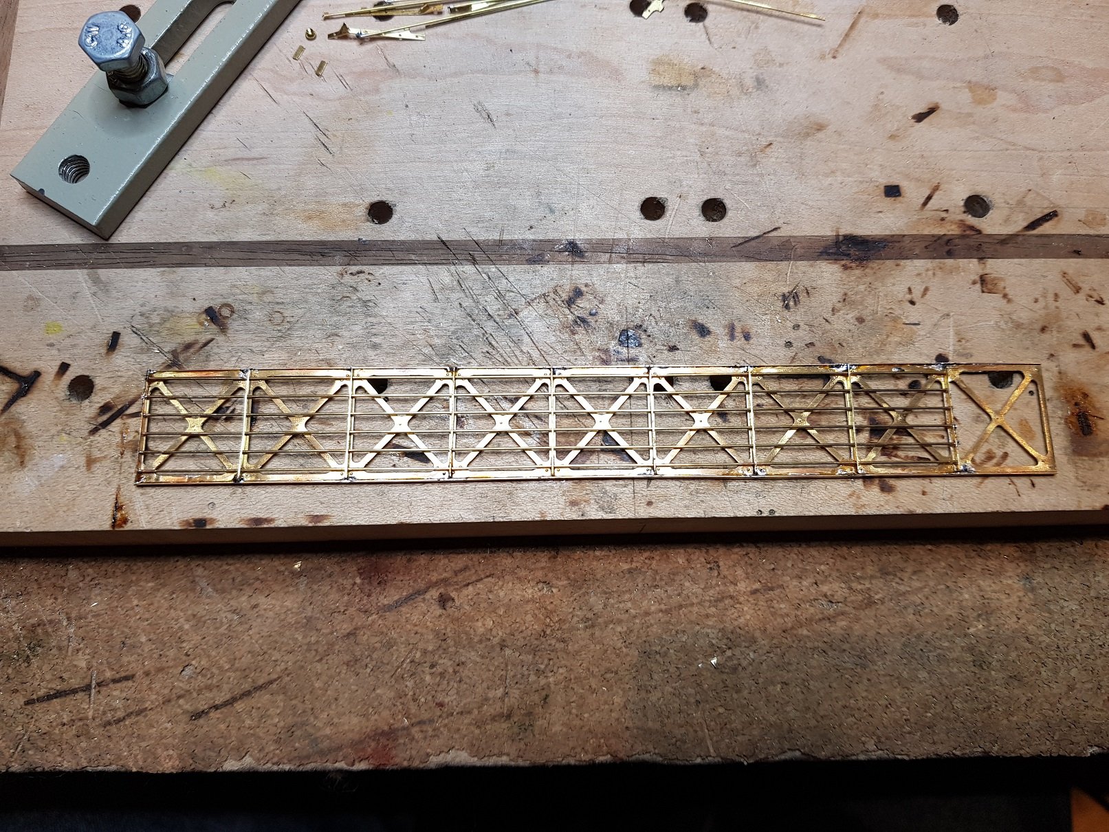
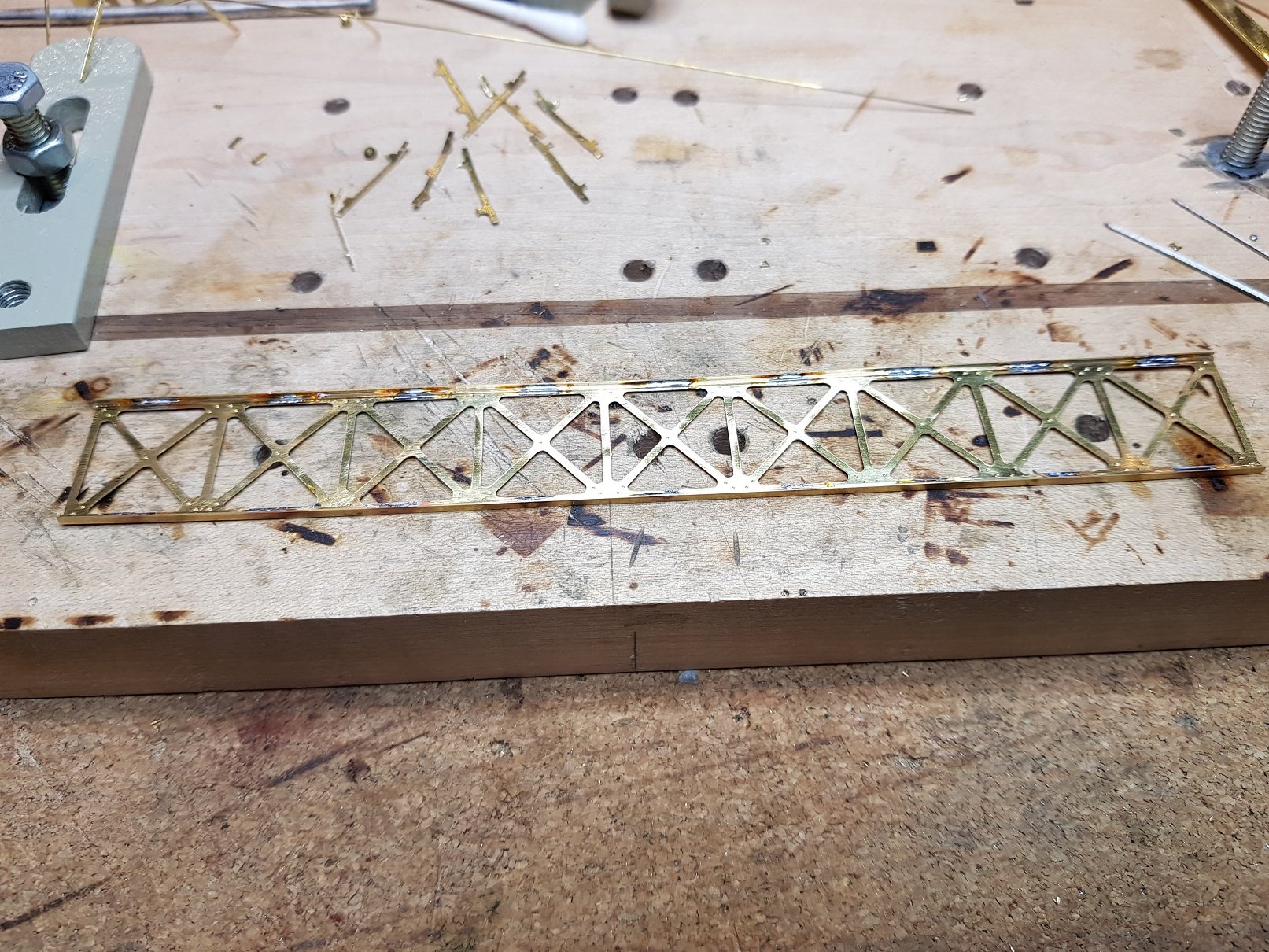
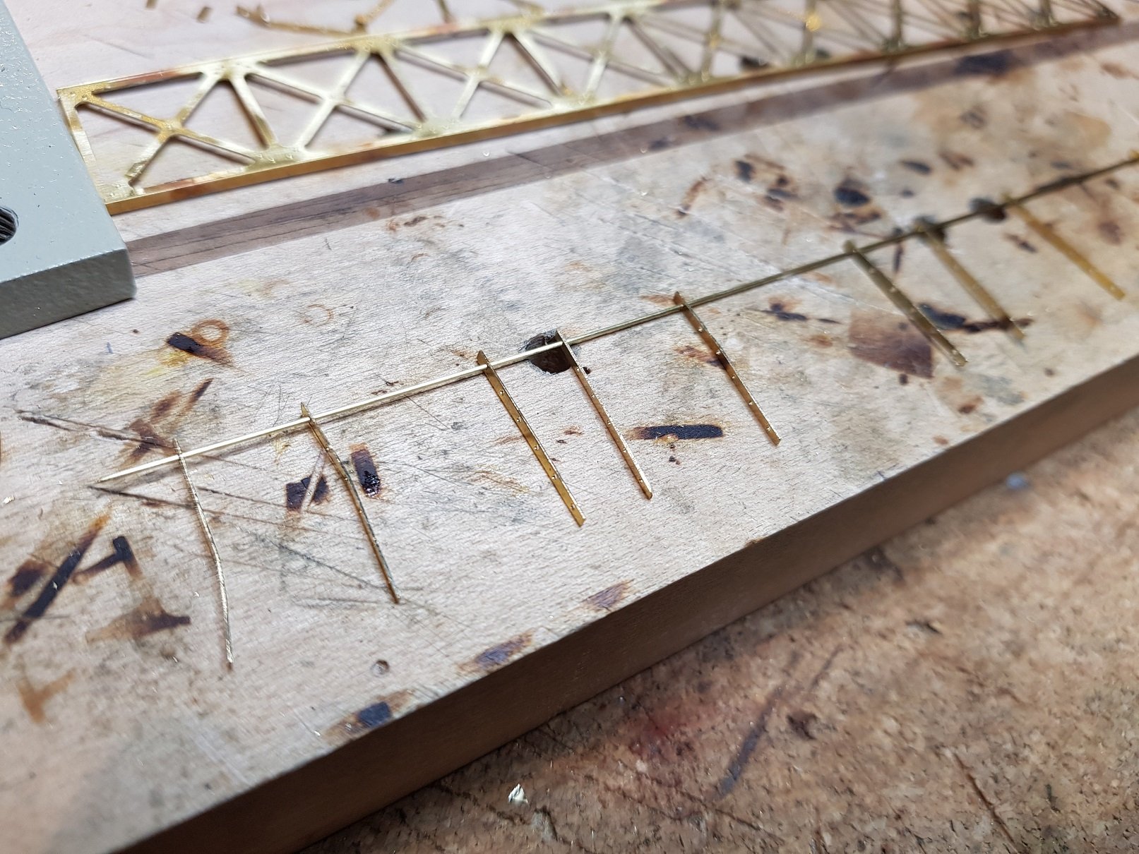
As mentioned in the layout section for Wicklow South, I intend to use the two footbridges to enclose the scene. The main footbridge over the platforms and a smaller one spanning the single line further south from the station. DSER constructed very similar footbridges along their network and for quite a few they were integrated with the signal box - meant only one stairs rather than two, so a certain element of fiscal efficiency. Prototype take recently. Rather that make the sides by soldering individual pieces together, I decided to draw up a plan for the base side in CAD & use the mill to cut out. It also made it easier to drill the uprights for the horizontal rods which will be much more accurate using CNC than by hand. The sides were cleaned up and t-section added top and bottom which soldered joints on the inside. Front side was kept clean with some rivets added. The uprights were a little fiddlier as threading through 6 no. 0.5mm brass rods took a some time being sure not to deform the uprights. It was worth the effort, as when uprights were soldered into position top & bottom, we ended up with this, which is starting to look good. Alas, I stopped too short with the rods as I was thinking the last section tucks into the signal box - it doesn't, so I'll have to amend that bit before ti gets to the model. More as time permits. Ken
-
Transport box suggests movement. Could we see Barrow St. displayed somewhere in the not too distant future??? Ken
-
I really like that asbestos roof - looks excellent! Ken
-
Ah - jaysus, and then I look at my lining attempts. Well done Eoin - pure quality. Note to self: must try harder!!! Ken
-
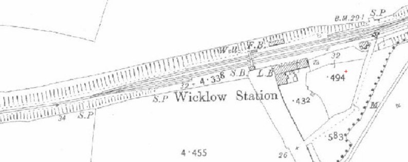
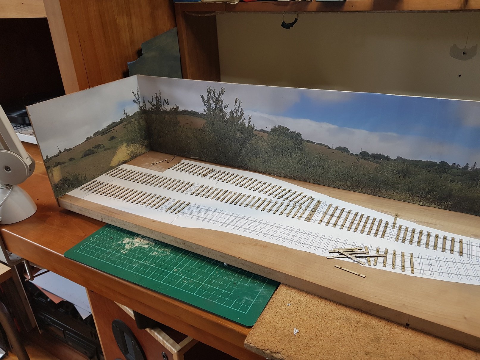
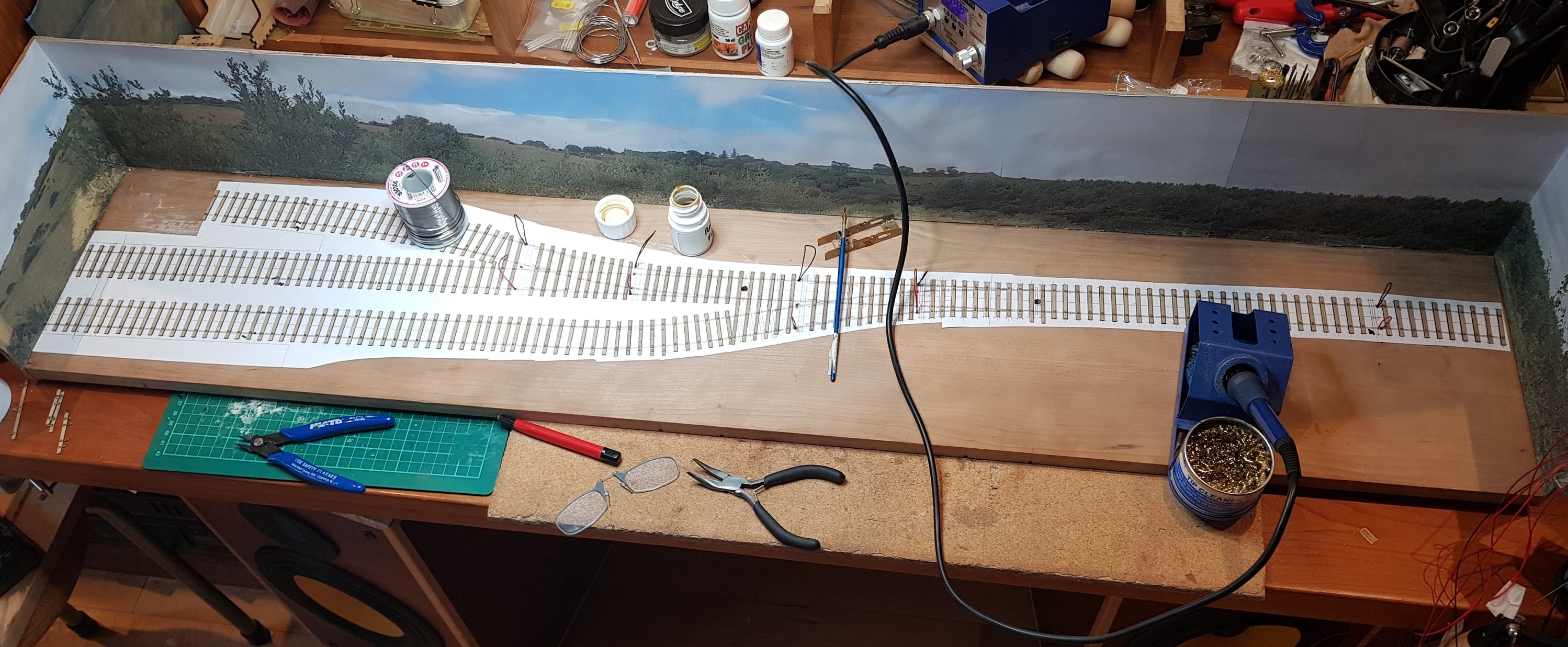
I decided it would be good to have a small shunting layout for testing purposes and also the possibility of bringing it to exhibitions. I started out to build an Inklenook sidings type layout without context, but decided it would be nicer if it could represent a station (or part of) in Ireland. The purpose of the layout is to sit over my work desk to be used as a test track as well as being transportable. Dimensions are 1235mm x 230mm which is really a glorified shelf layout. After looking at quite a number of stations to find something that would fit (ish) in the small space i had in mind, if found that the southern section of Wicklow Passenger station may fit the bill. So the plan is to model the South (West?) end of the station from the foot bridge over the platform to the pedestrian bridge over the railway further down the line which should frame the layout. Understandably, the layout is truncated to fit in the space available. So - layout developed in templot and CAD to get some track plans to start track work. Wiring done - DC with isolated sections to allow multiple loco operation if required. Track & points built, all fine tuned and running well. Well...........almost. Turns out the points (A5) were too tight to allow the larger locos through. The 0-4-0ST (495) worked through without problem, and 2-4-0T (423) just about made it, however the 4-4-2T (458), & the 6 wheelers would not and were continuously de-railing. Back to the drawing board (Templot & CAD) to create A6 points, tweaked to fit in much the same space. Old points removed & new trackwork constructed and fit. The advantage of building track is the ability to tighten up track work rather than use set track. By pulling the RH point back into the exit of LH point helped shorten the overall length. The point blades for the RH point are rather close to the crossing vee of the LH point which with a bit of fettling works well. The only issues to over come were ensuring isolation between the crossing vee and the straight track of the new point to avoid shorts; the second being the kink in the track at the blade tip for the curving rail. There was very little track before this kink which took some time to get right. All tested and up and running. All locos, coach and wagons now get through the points, albeit at slower speeds for larger locos. All good. Points are controlled manually by a rod under the board with a pin coming up through the stretcher bar between the blades. Electrickery for the crossing vee and wing rails is controlled by powered pins & a side branch on the point rod. I'll take a photo as it's rather difficult to explain! So track & sleepers painted ready for ballasting. I decided to model the prototype and add point rodding using the Wills kit (base kit & extension); main point and catch points picked up closest to the viewer which will pass under the track at the signal box. The short siding catch point will be picked up on that side back to the signal box. I also have signal wheels to model the signal cabling which is yet to be done. Signals to be built including ground signal for the siding which will be of the lattice type. Signal box, partial platforms, DSER style bridges, ballasting and scenics to be completed, so only really getting started at this point. What I have learned is that the trackwork on the other layout (Port Cumtha) will need to be re-done as this experience has shown that the locos & 6-wheelers will not get through the points, but that's for another day. More as time permits. Ken
- 17 replies
-
- 11
-
-