KMCE
-
Posts
540 -
Joined
-
Last visited
-
Days Won
29
Content Type
Profiles
Forums
Events
Gallery
Blogs
Everything posted by KMCE
-
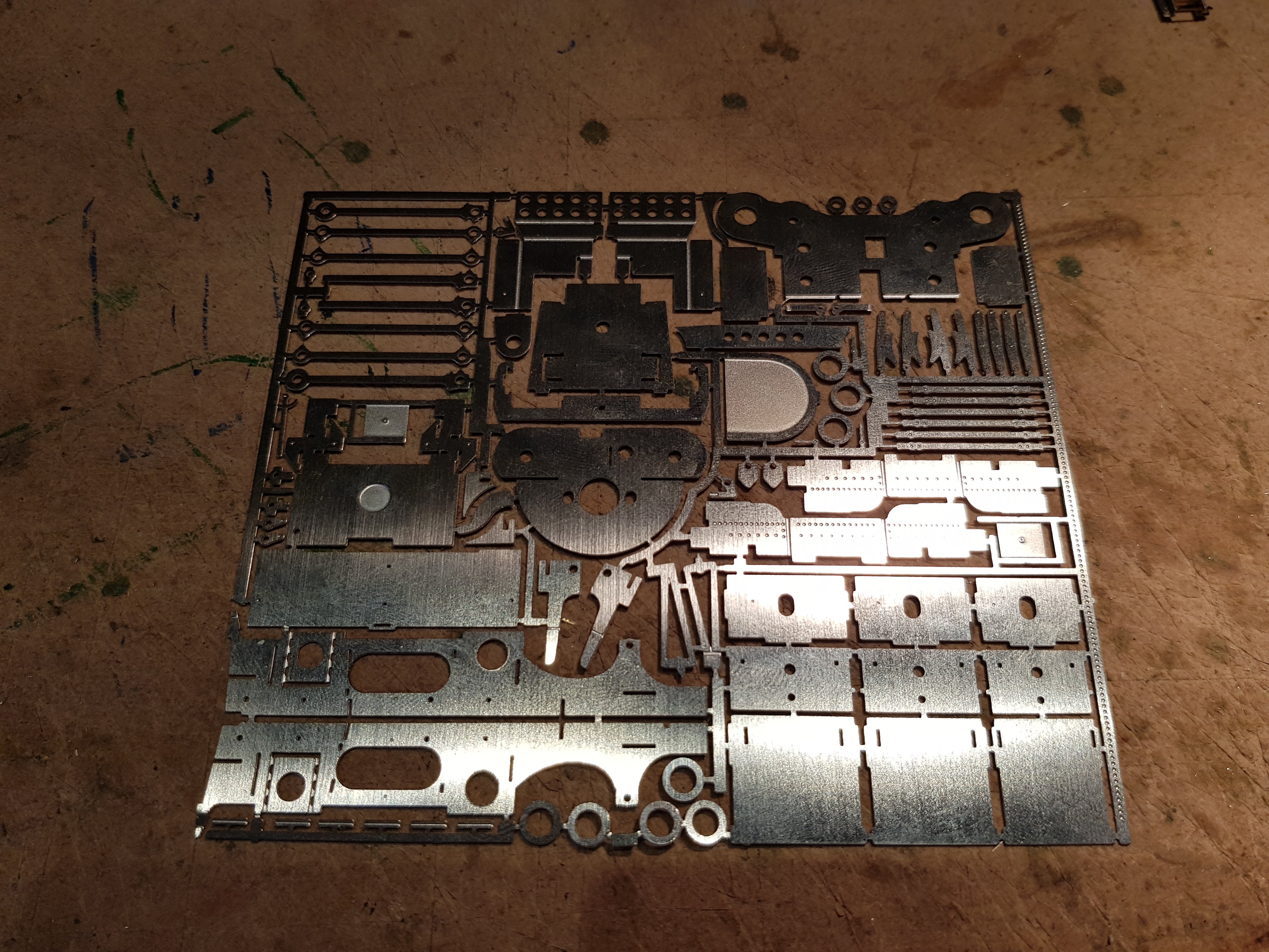
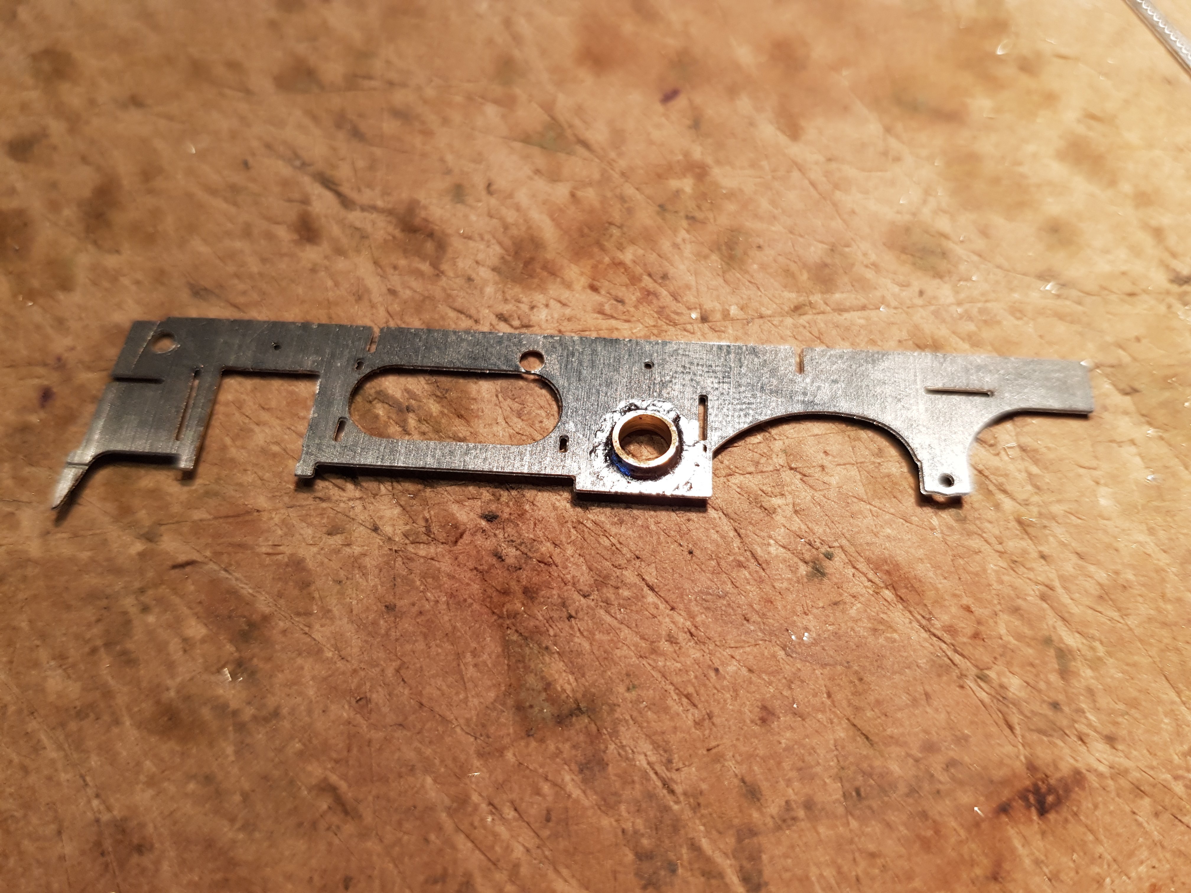
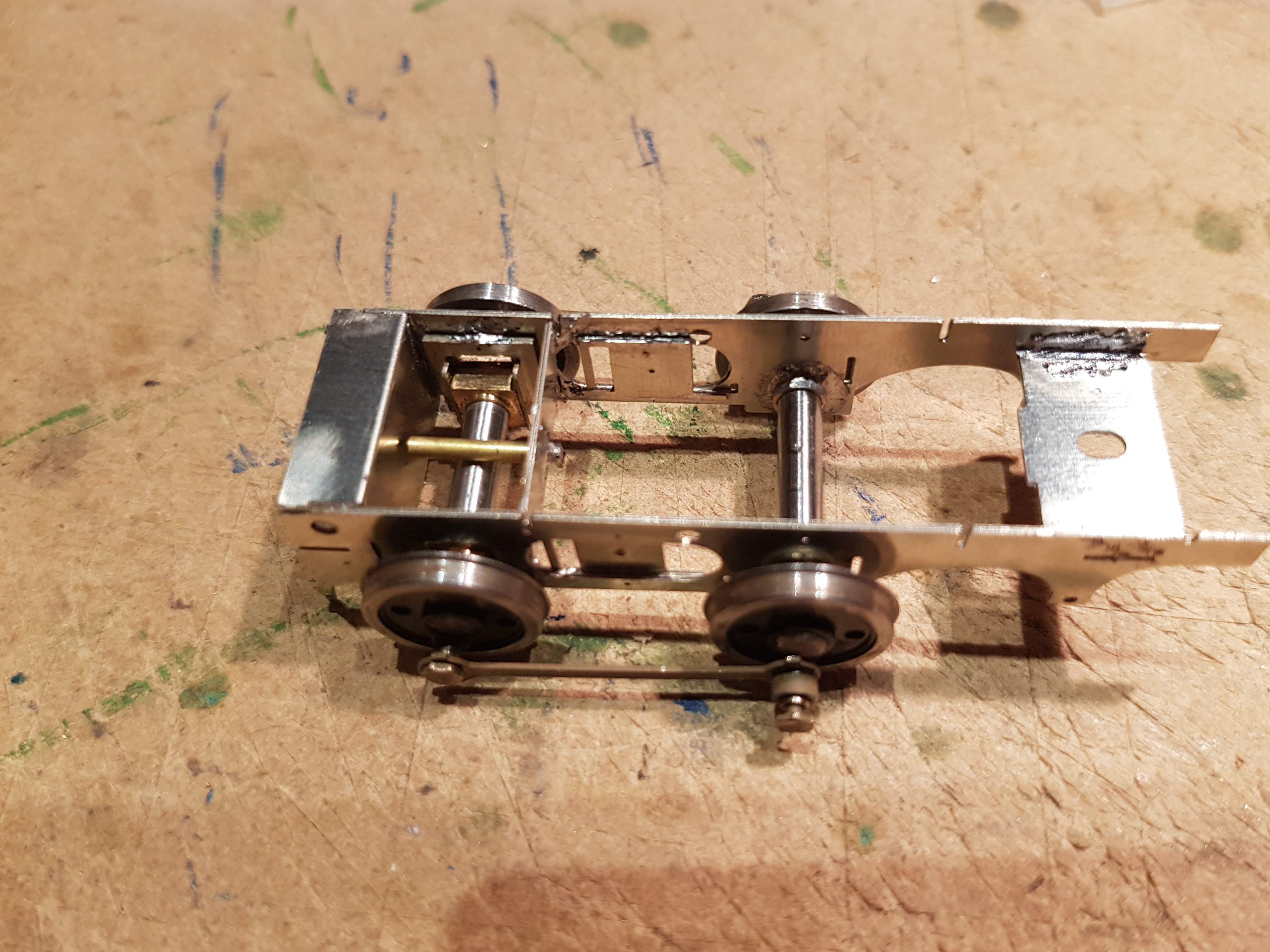
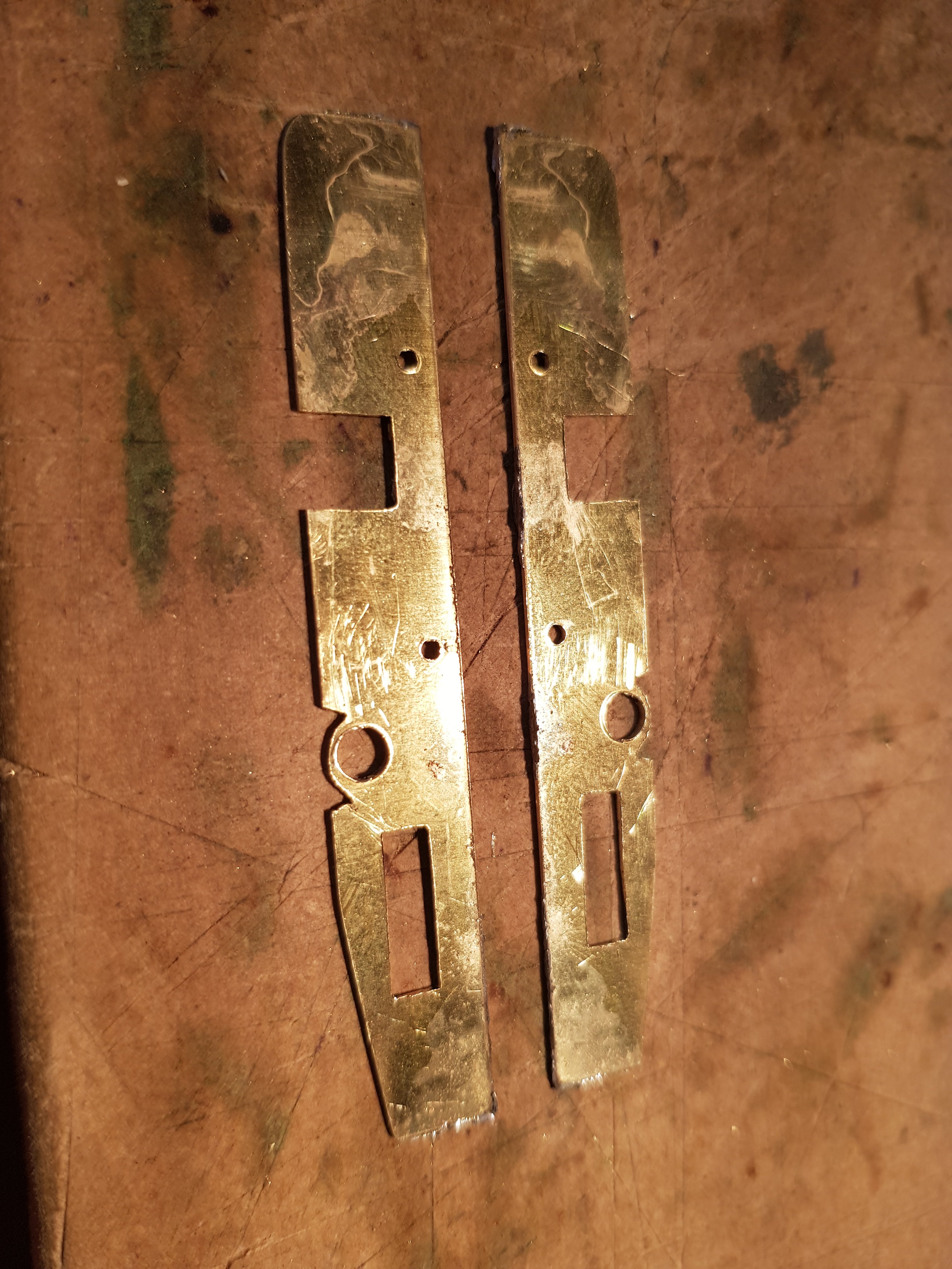
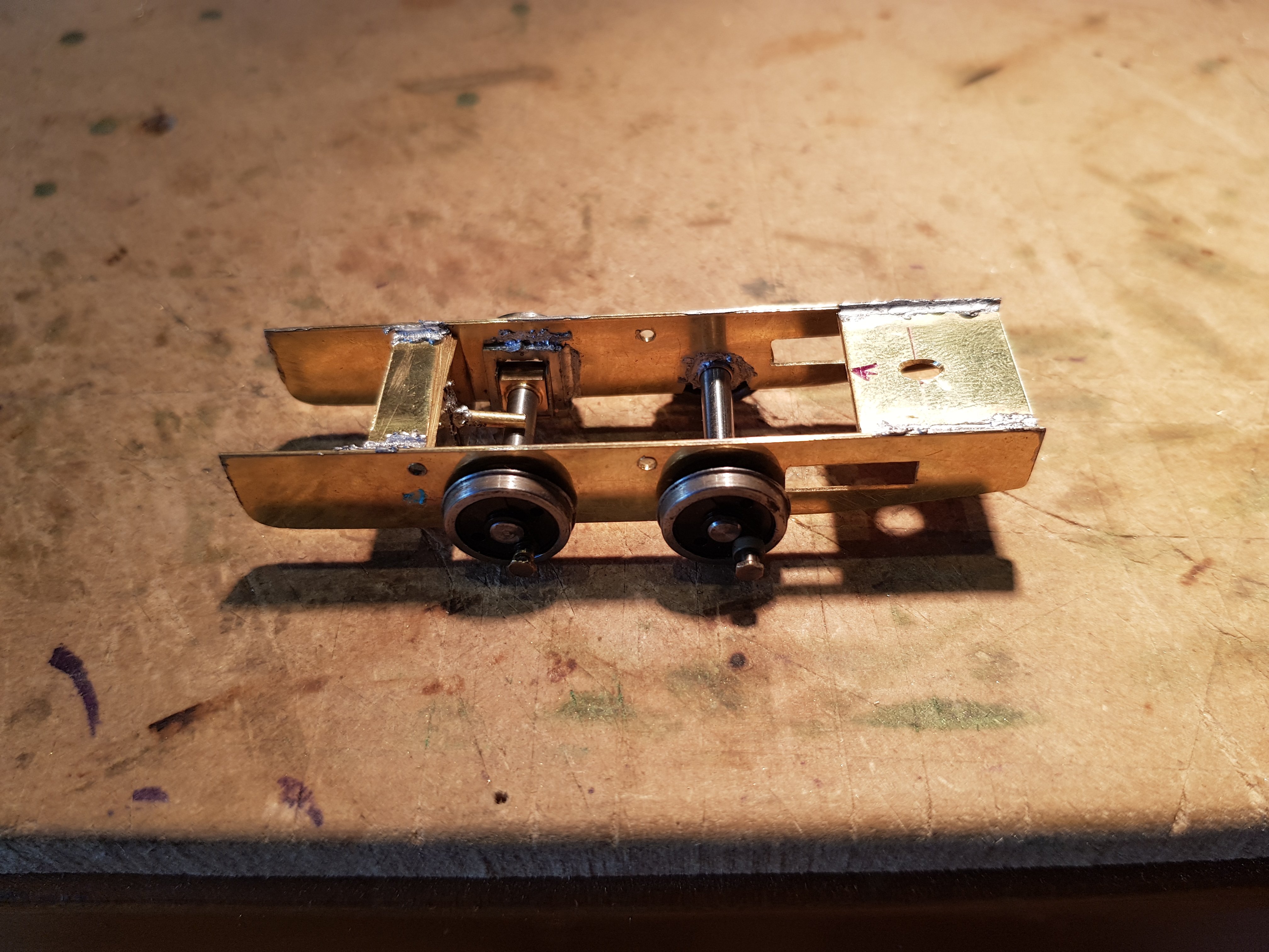
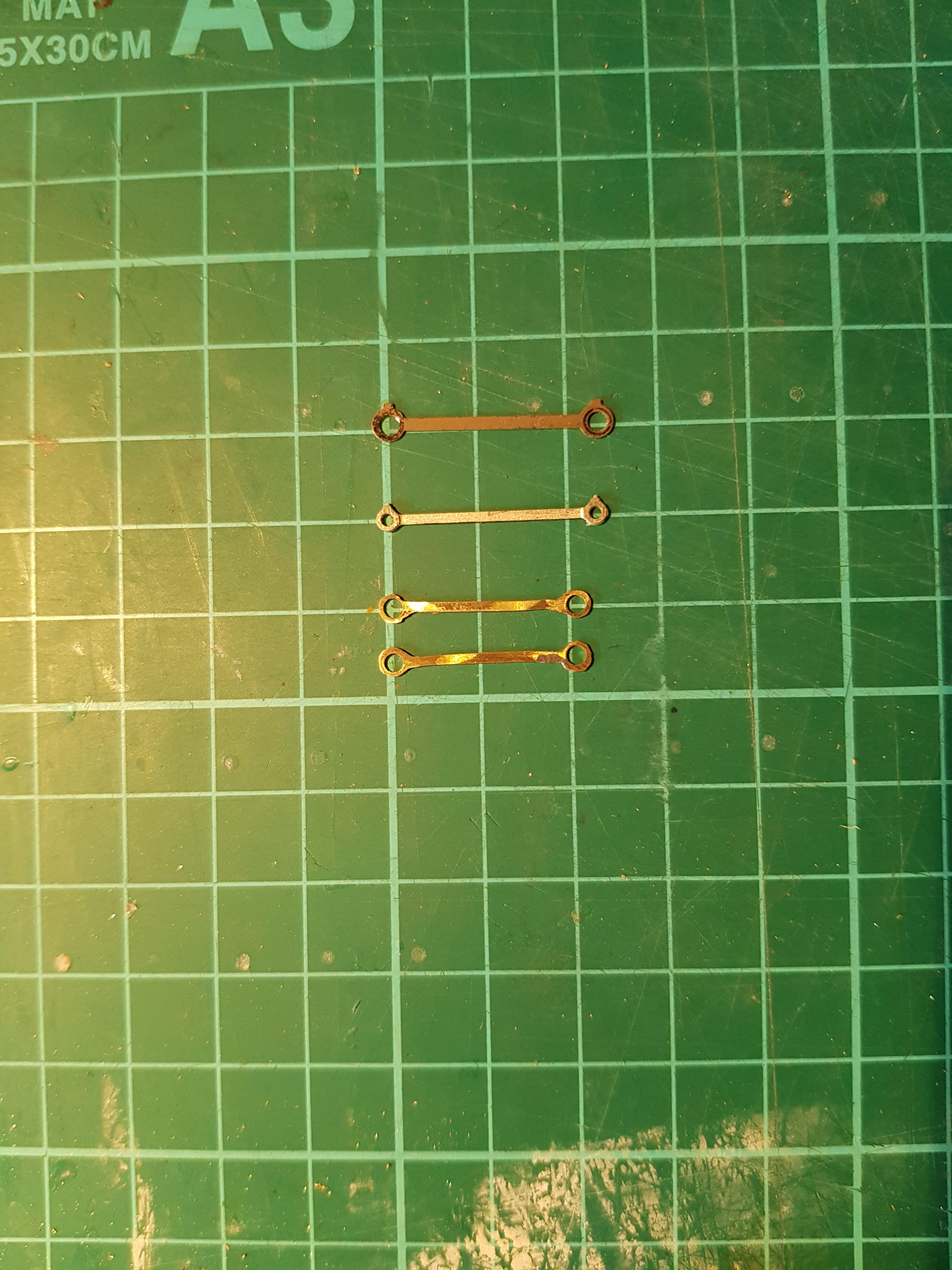
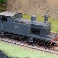
Right........ Now that I have a properly printed model it's time to get started on construction. As mentioned in the earlier thread, I was proposing to use the high level kit as the chassis under the printed model, so made a start on the kit. The kit has parts for OO, EM & P4, so there are a few additional etches. Frames cut out of fret and bearings set in rear axle position – hornblocks for forward axle. I built the chassis up using the P4 components in the kit to arrive here: However........ Due to the 21mm gauge there was a lot of slack between the wheels and frames which was causing problems with how the loco sat on the track - the side play was excessive and to be honest the chassis was not the right shape anyway, so I decided to start again and build my own frames. More reflective of the actual loco, and allows me to correct the spacing to prevent excess sideways play. We get this: Great - right shape, compensation in, ride height set - now for rods. Ahh....wheel base in the kit is longer than 495! Thus coupling rods are no use, so I had to make my own. After using all the expletives I know (many times) and three goes later, we now have coupling rods - sort of! Not as elegant as the etched ones, but the difference in length can clearly be seen. Original RTR rods top, kit etched second, mine bottom. No lubricating pot, but I may be able to bodge something together. Now we are starting to get to a point where cylinders and connecting rods can be added, brakes fashioned, pick ups added and hopefully we will have a completed chassis. I hope to use parts of the kit to add detail to all of this, particularly in the cab area which will be very visible. More later.....

-
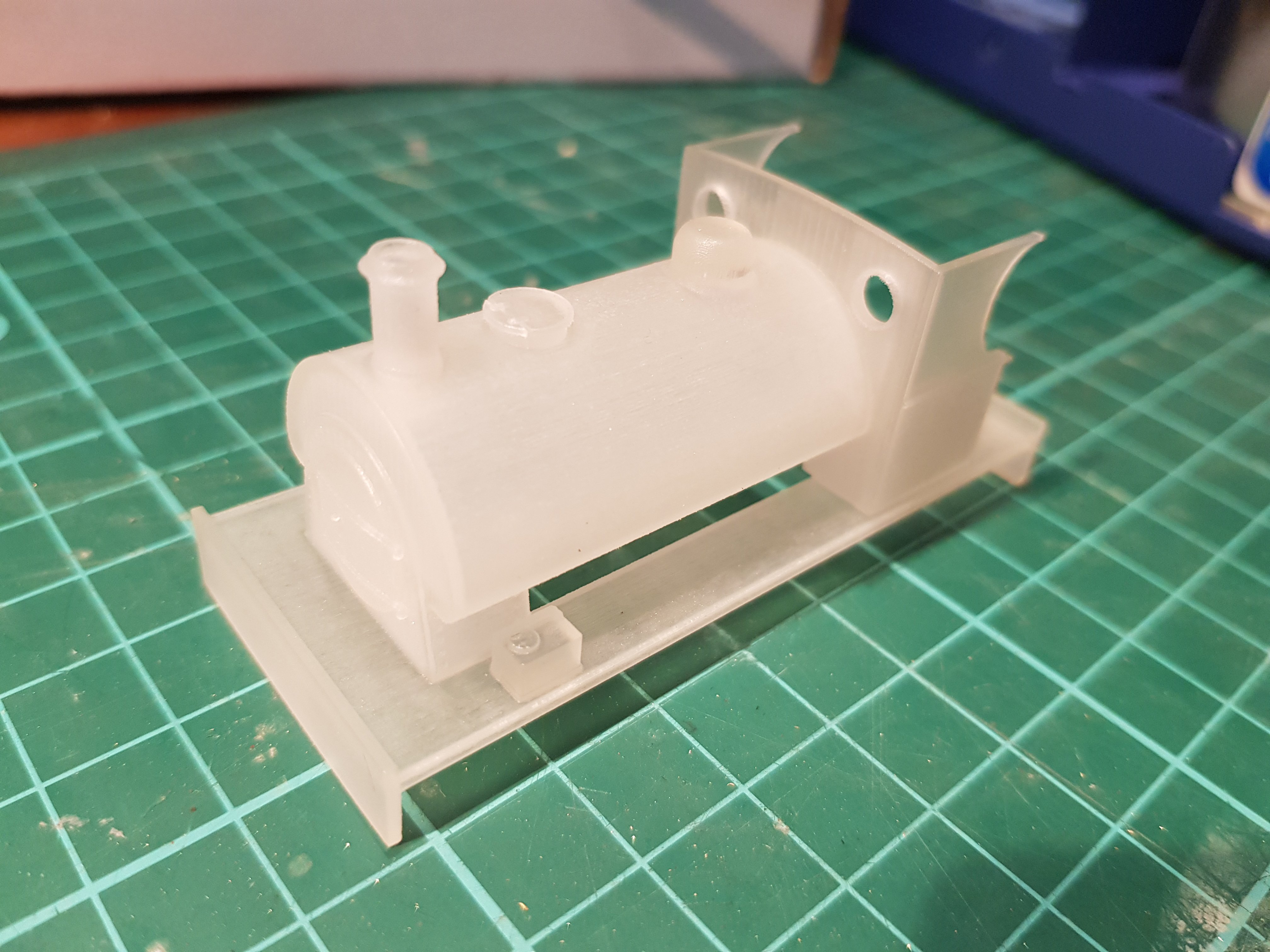
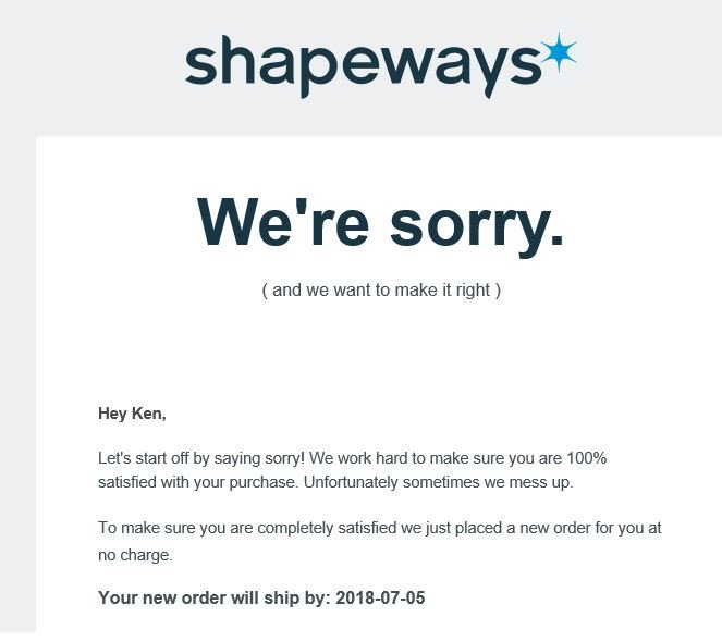
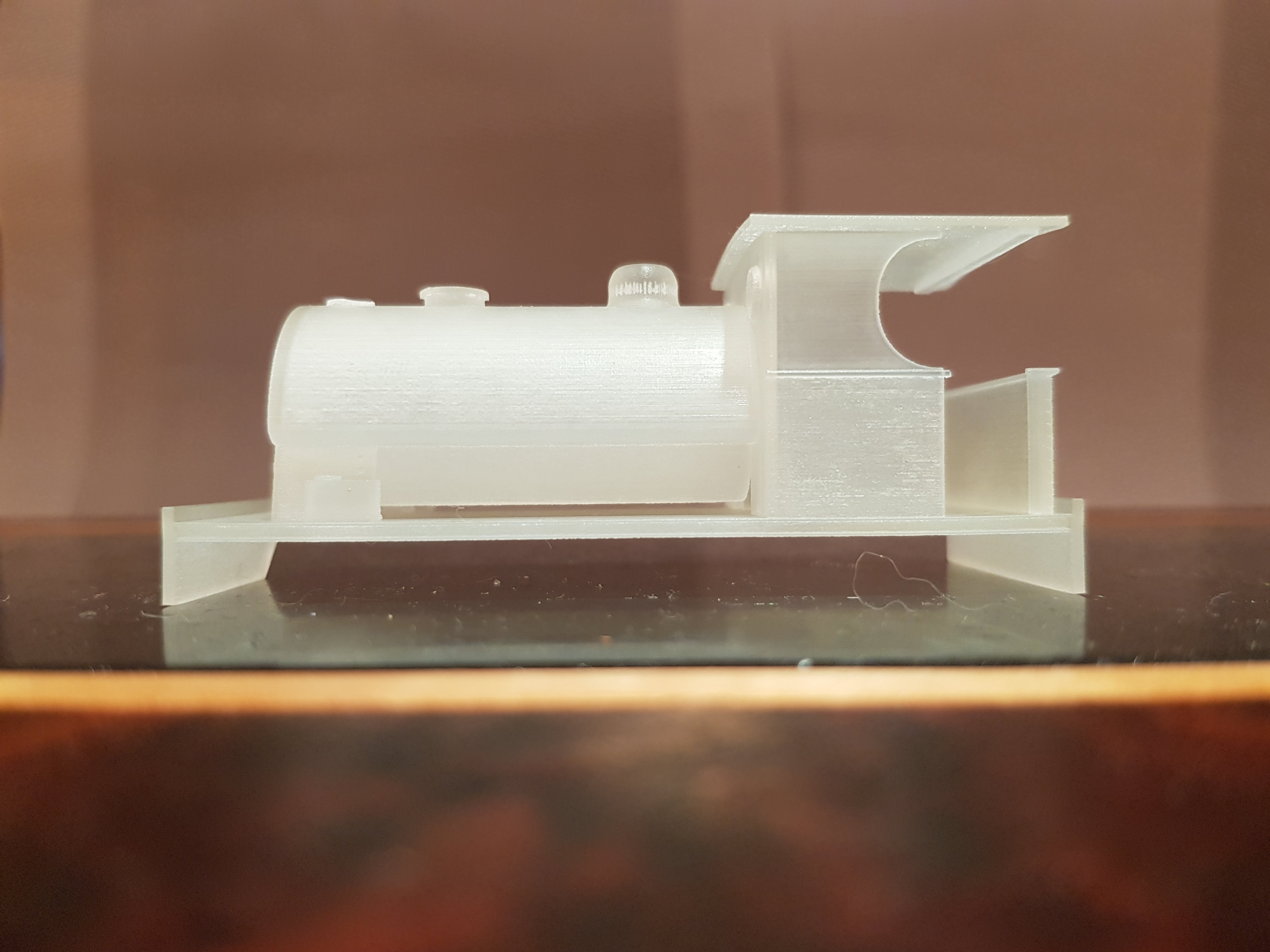
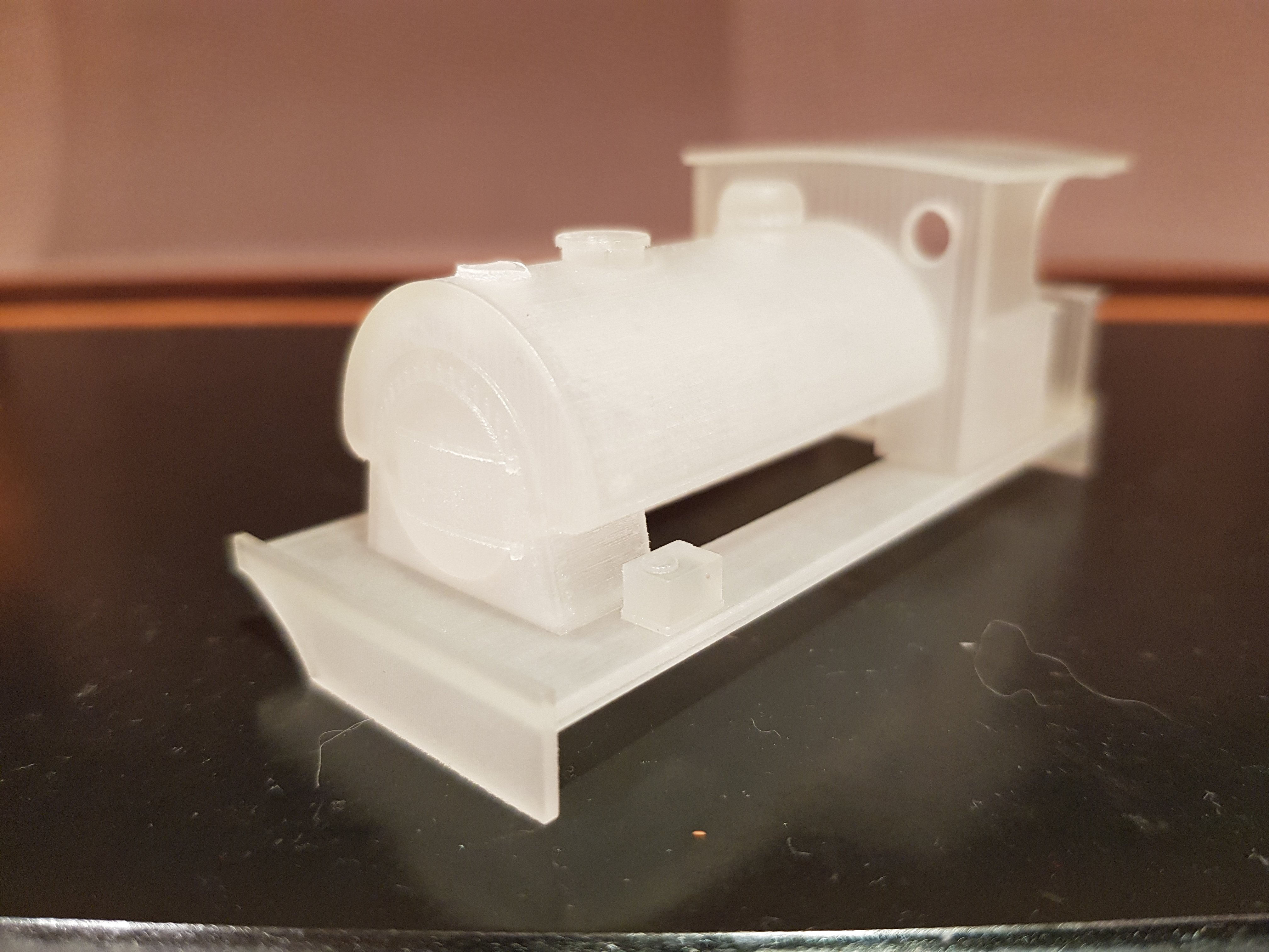
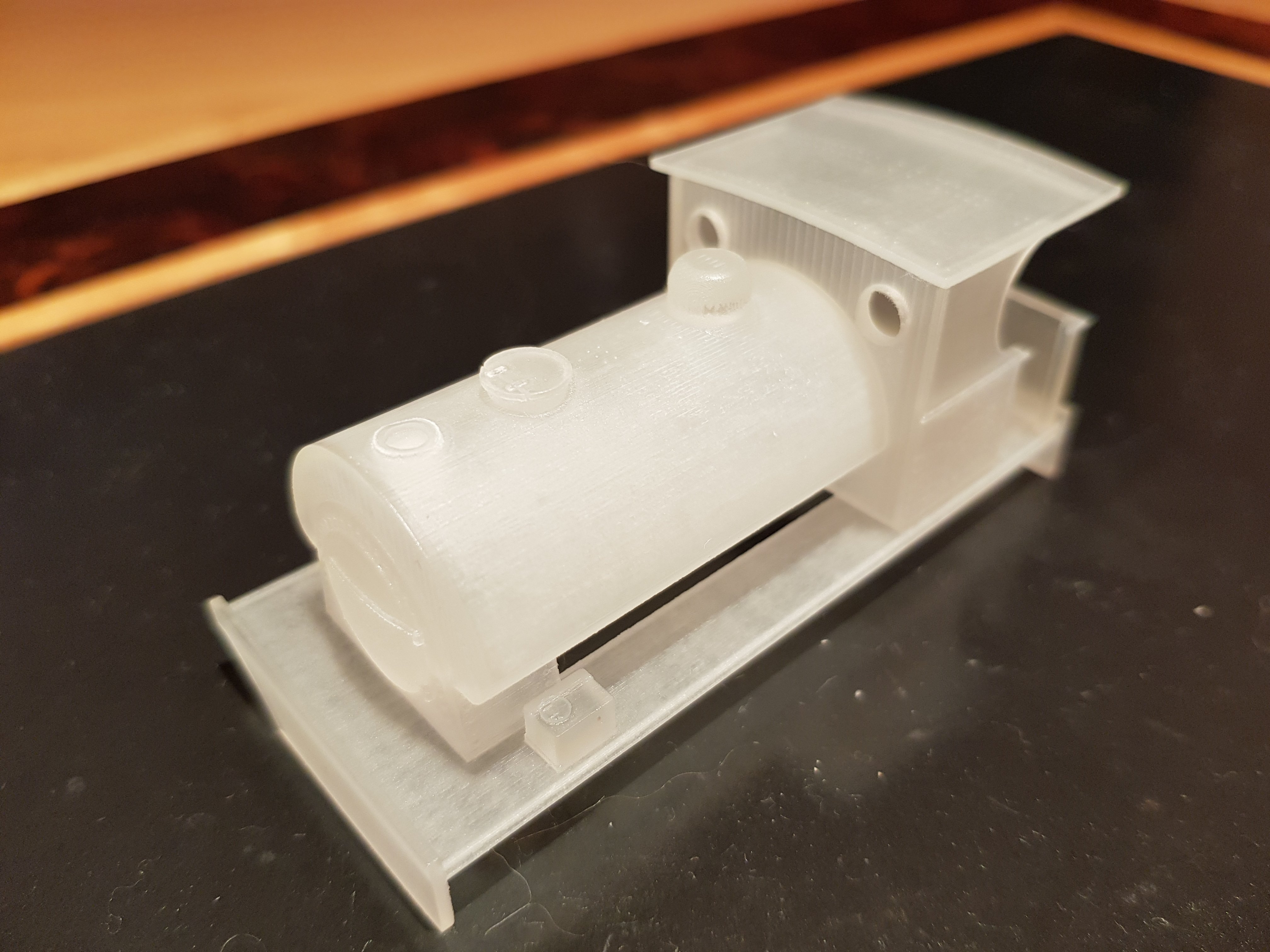
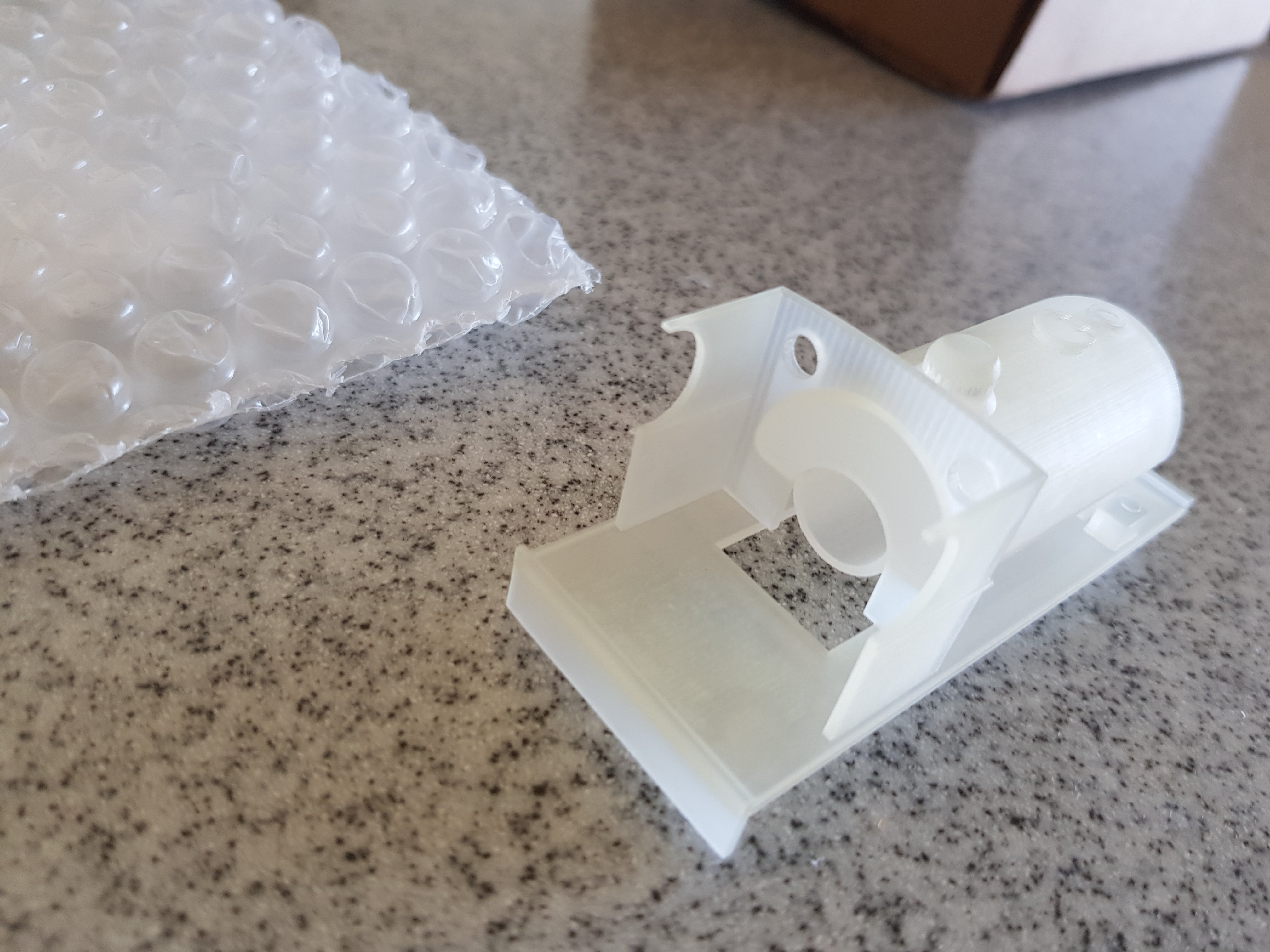
Re-printed model arrived. Printed properly this time Now on with the build!!
-
Now that is a stunningly impressive model and associated talent bringing it together!! Well done Eoin.
-
Quick update: Dropped a note to Shapeways pointing out the broken parts on the model, and in fairness to them they responded quickly. In fairness, you cannot complain with that level of service - I'm very impressed. Looking forward to take two!!
-
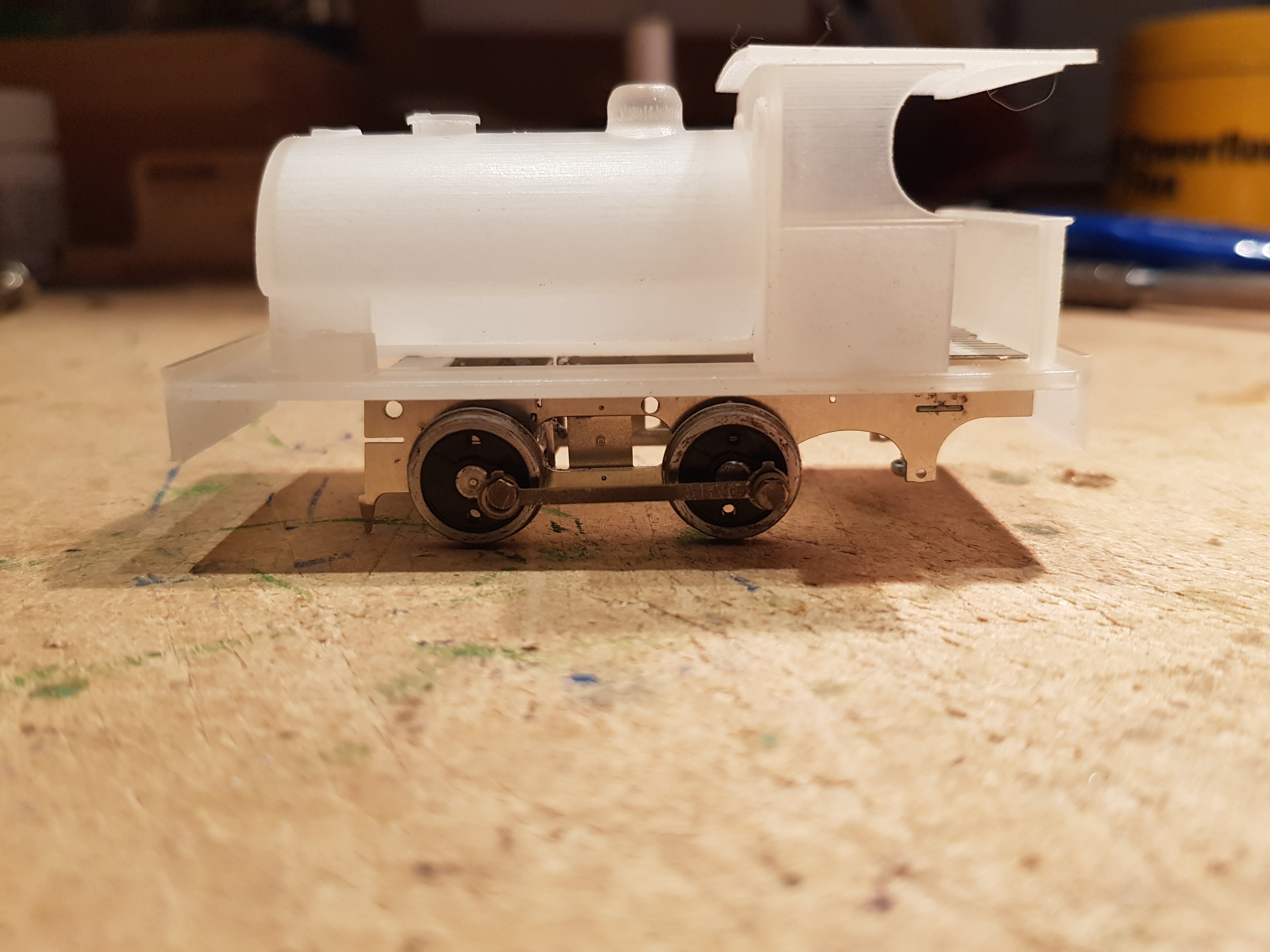
Well...... Model went to Shapeways for printing. The system wouldn't accept the buffers, as the edge was too thin for their printers, so just left it with blank buffer beams - I can always add buffers later. € 58 lighter and 12 days later, a model was delivered to the door!! Cab roof and back were printed separately to allow me to provide detail with out the keyhole surgery!! Now the erudite among you might have noticed the the buffer beam is incomplete / broken, and the chimney appears to have been printed inside the smoke box! So a friendly chat with Shapeways will be needed to see what happened. They are not major issues, but other details appear to be good, so what's with these two errors? As for detail, rivets on the tank body did not render, however on the smoke box face and cab made the grade. It appears fine detail will render on flat surfaces, but not on curved shapes. A light coat of primer may help to raise more detail, as it is a little difficult to see the detail given the material its printed in. All in all, pleased with the result for the effort put in. Let see how this looks with some paint and sitting on a chassis. I may start a separate thread on the build of 495 rather than continuing here as the discussion has moved on from 3D printing. More soon......
-
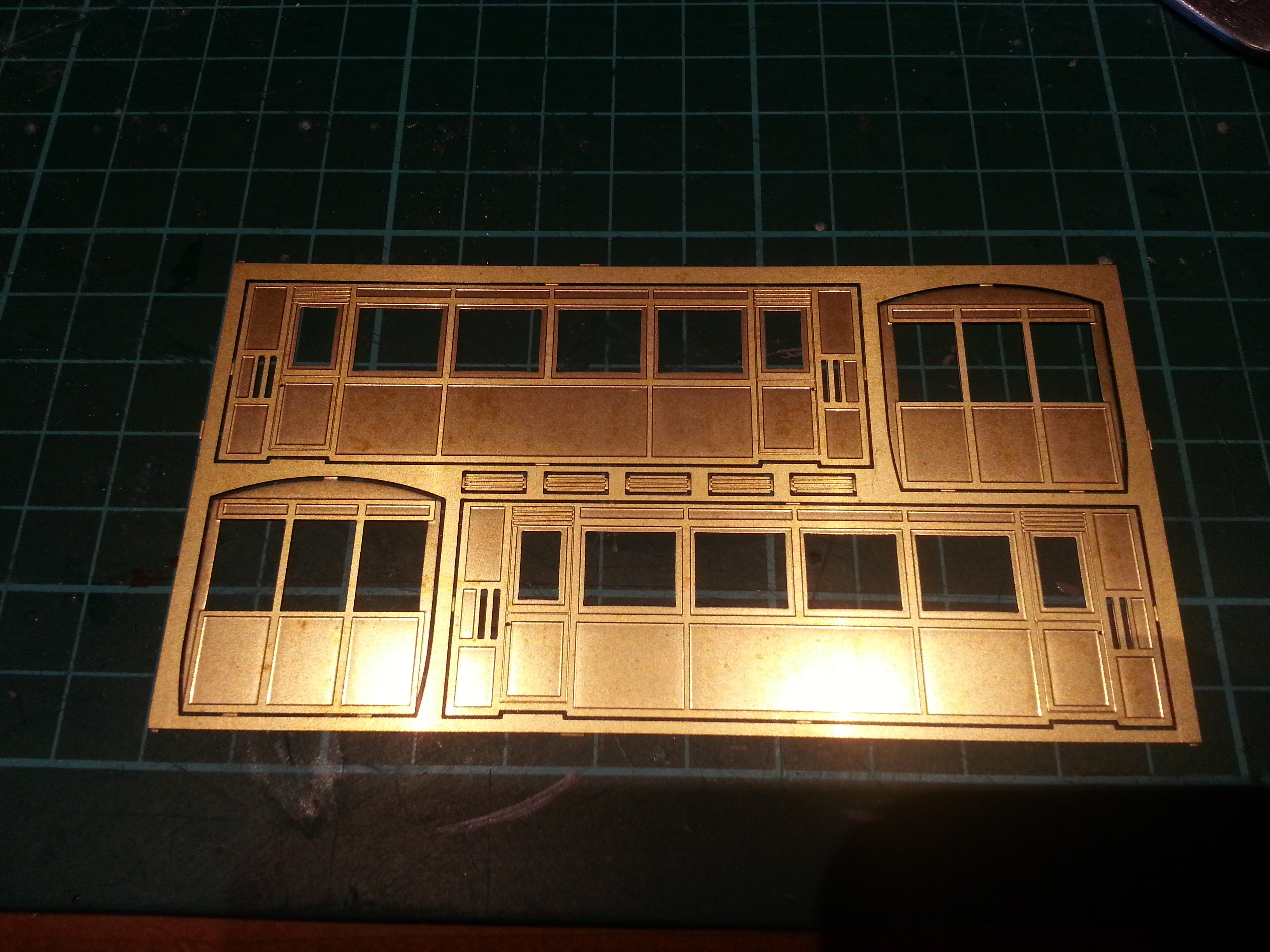
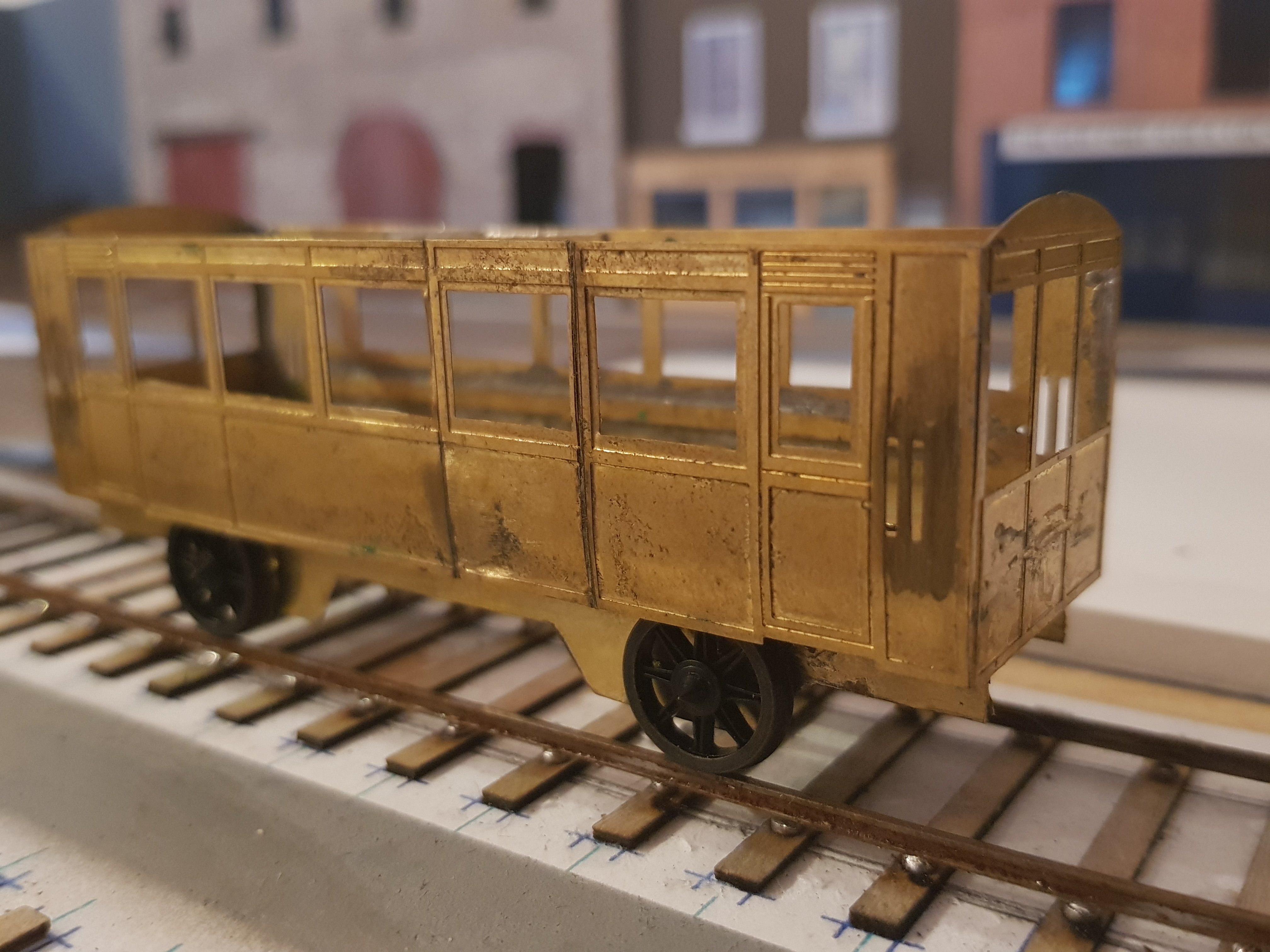
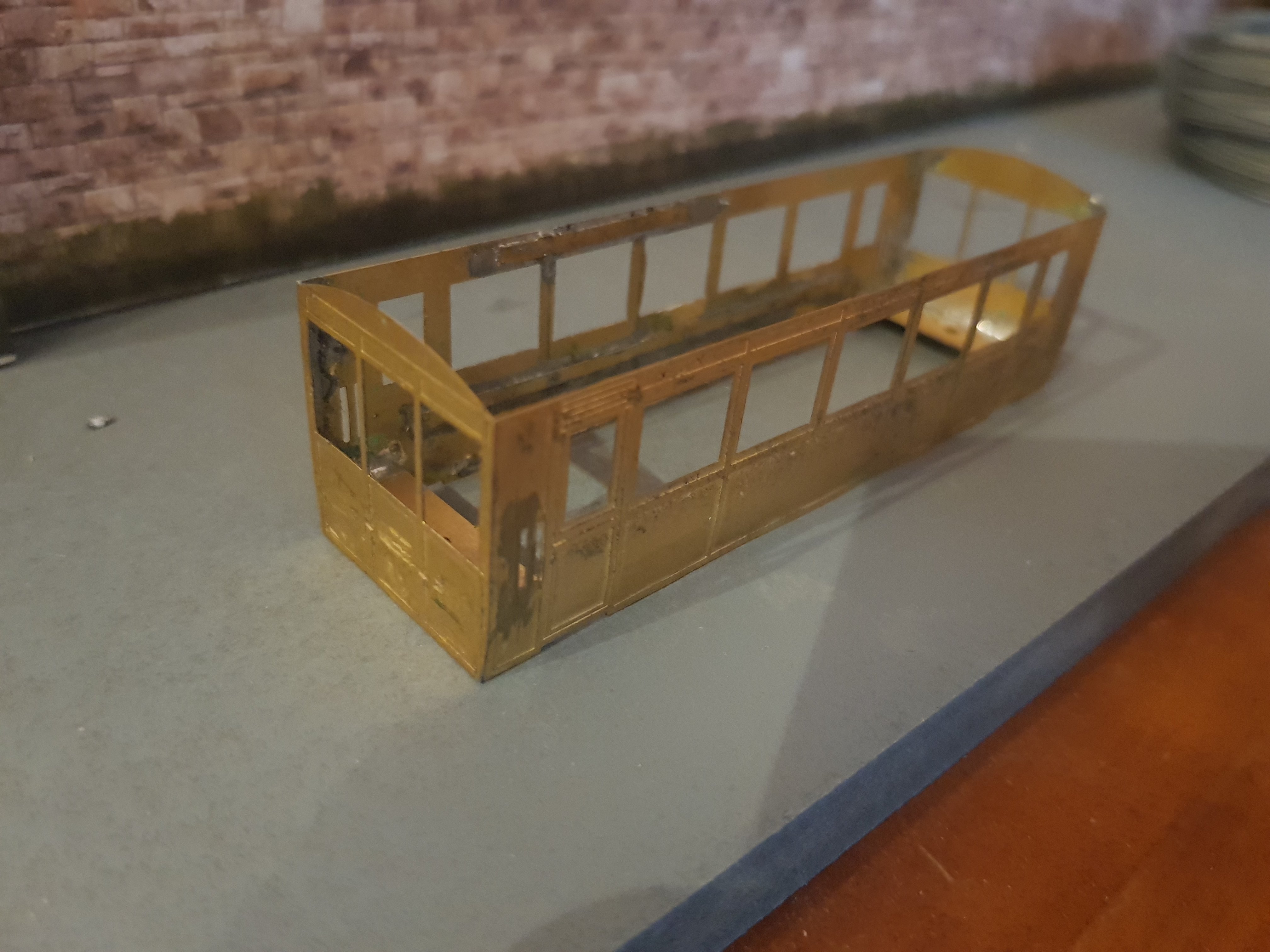
JHB et al, My search for information on this type of railcar has led me back here - should have started here I'm in the process of building one of these rail cars and am using the Worsley Works Kits to produce a broad gauge version and am running into trouble with the chassis, as the available photos do not provide enough detail. Progress to date: Scratch building aid kit as delivered (x2) Removing narrow gauge handles prior to splitting the body to insert the additional window (hence the kit x 2) Panel inserted and body made up. Scrap brass used to hold the inset section. Basic chassis made to set levels (wrong wheels - correct on order) but now need need a little more information to develop a more accurate chassis / underframe assembly. Is the information noted above still available?? Here's hoping... Ken
-
Hello MikeO, I am planning on using the High Level Pug Chassis - http://173.254.28.51/~highlev3/chris/Pages/pugpage.html I will need to make some mods to this kit to allow for the 21mm, as it only allows for the 18.83mm P4. It may simply be spacers between the wheels and chassis and build chassis as per the kit, or introduce new cross-members in the kit to build out for the 21mm. It may be simpler to use spacers. The 3D model is nearing completion, and I may put it out to Shapeways to get their call on whether it will work and costs etc. Ken
-
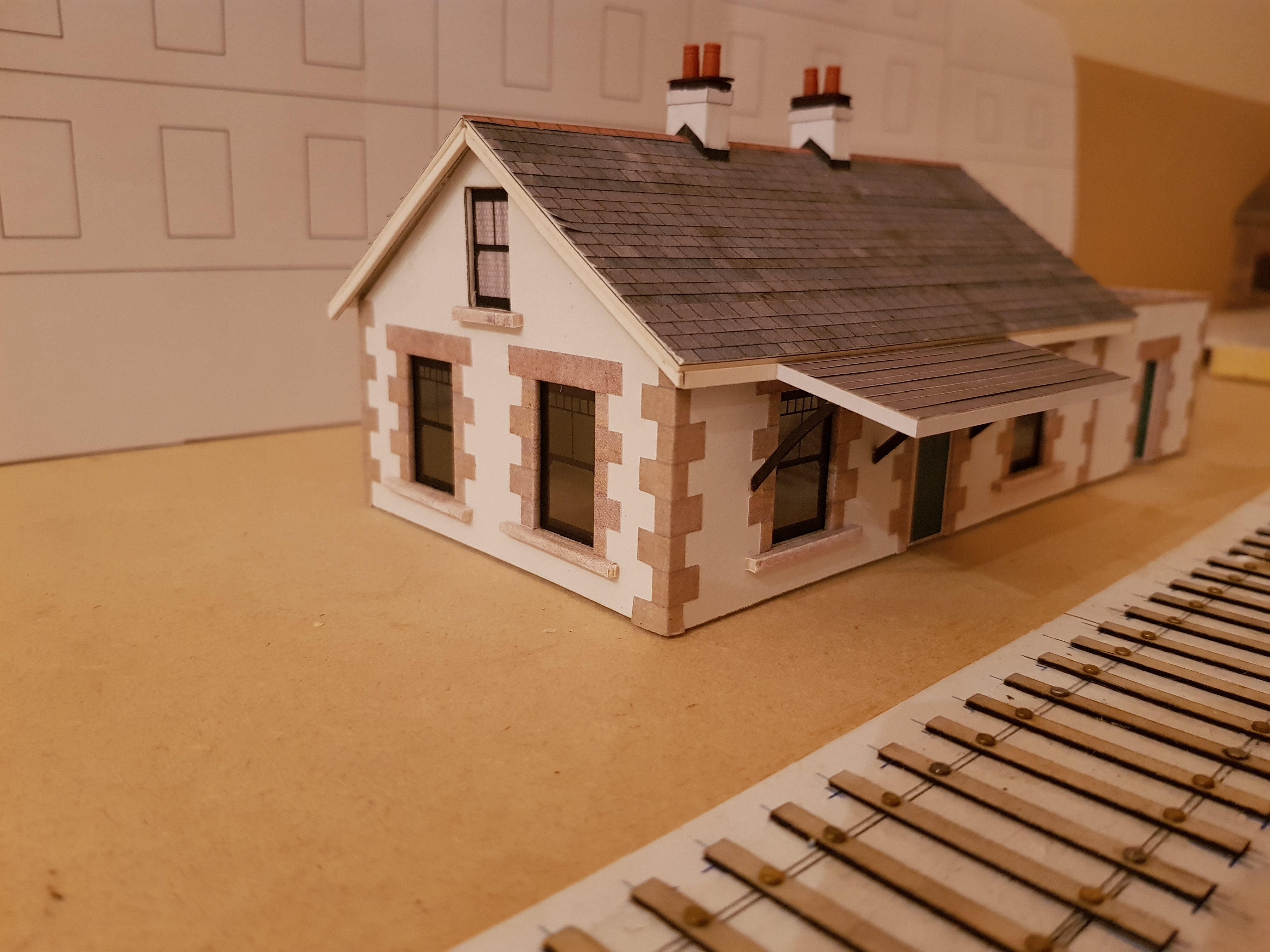
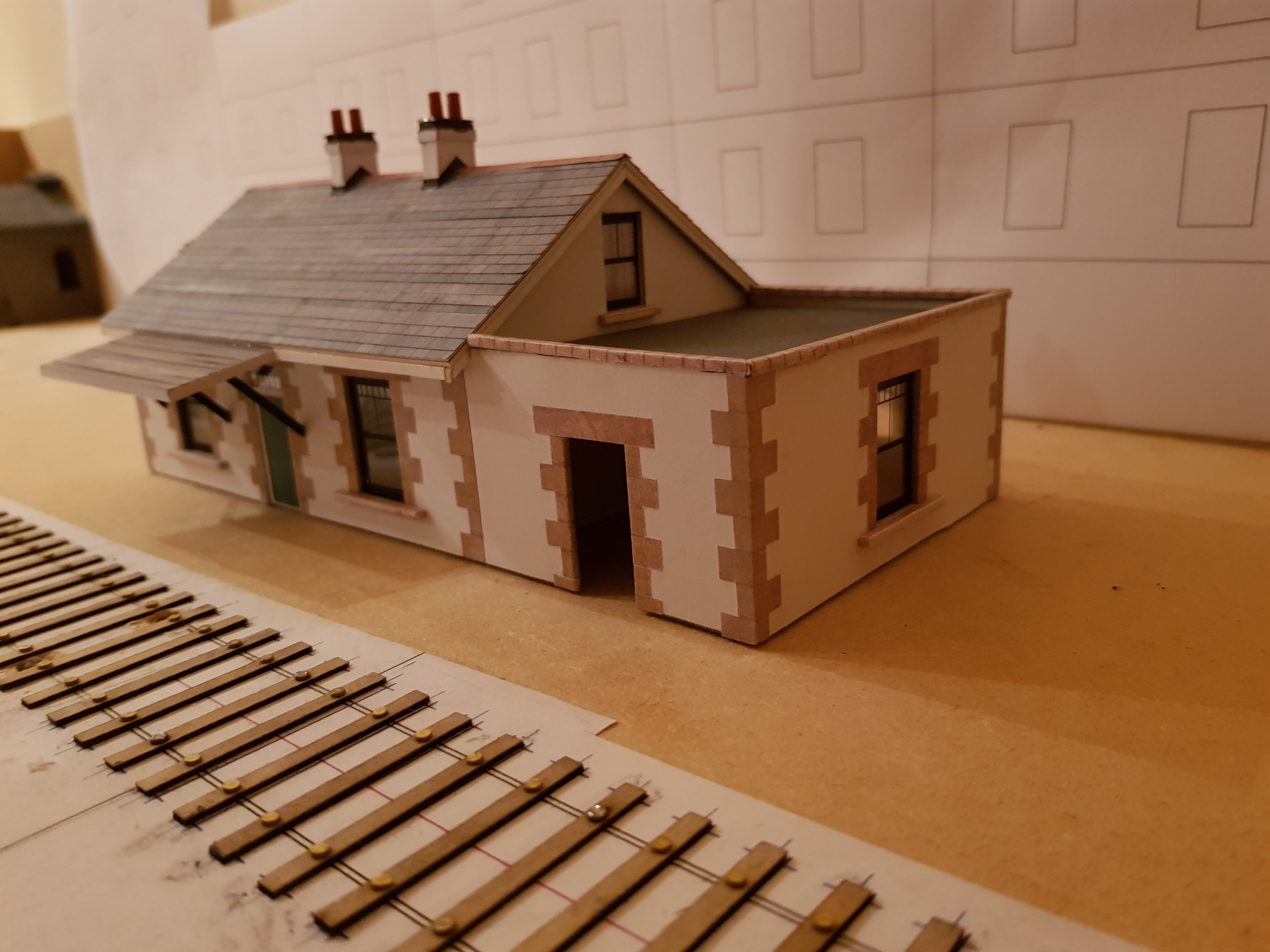
Hello Derek, That's a cracking start to your layout. By coincidence, I also used the Florencecourt station house in my Port Cumtha layout due to its small size and good detail. I modeled it as it is now, rather than how it was, as in my case the layout is fictional (hence the name!). I'm working in 4mm, however given the amount of card cut for the various buildings on my layout, that cutting machine you mentioned, does look interesting and may have saved my fingers!! Good luck with the layout - one to watch. Ken
-
Getting the hang of this 3D CAD. Progress to date. Few more bits and pieces, and we may have model to print!!
-
Hello Robert, The sleeper length is 36mm (9ft) if I recall correctly. In terms of setting the track out, templot is what is generally used. It's free to download and use, however it is a bit clunky to operate initially. You need to set up the scale you want (5'3" gauge is there) which sets out all the necessary parameters to allow you set out sleepers, track lengths, and points etc. For spacing, I bought the gauges from Scalefour society (there may be others?) which are not expensive - you could make your own, but for the sake of c. £5, is it worth the effort? Hope this helps, Ken
-
 There is the option of painting white circles on the tender and smoke box and run her as an oil burner, post-war?
 -
Eoin, Thanks for that - as mentioned, I want to get these scanned so they are flat and in proper digital format. Once they are in digital format, they are available to anyone who wants a copy as they should be dimensionally correct. Hopefully, I can then import them to CAD and draw them up when I have time. On the issue of sourcing drawing, I am looking for a few as I would like to build some ex DSER / GSR locomotives: Class 423: 2-4-0T Class 434: 2-4-2T Class 850: 2-6-2T Does anyone have a copy, or know who I can get in touch with to source a copy? All assistance gratefully accepted.
-
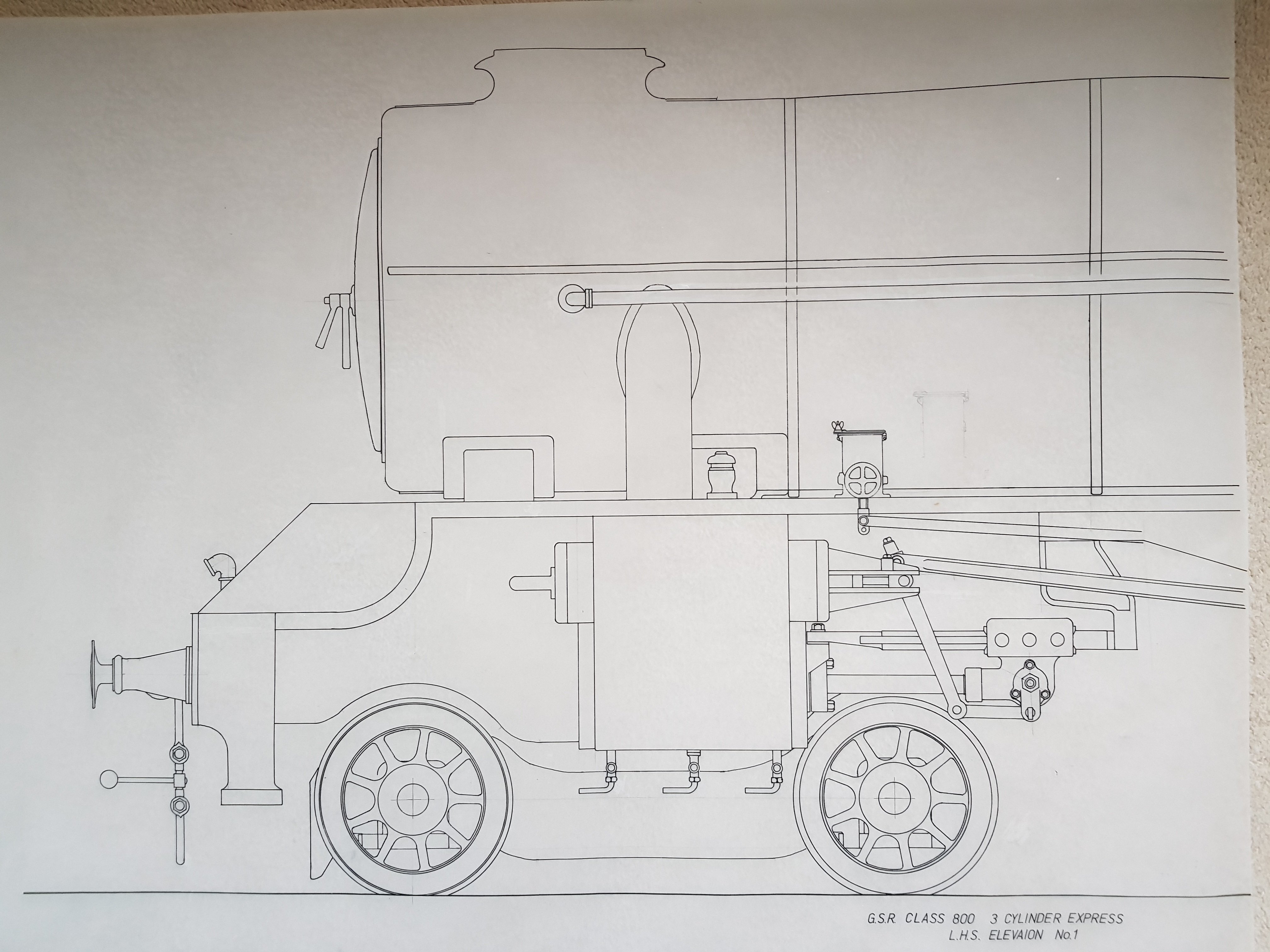
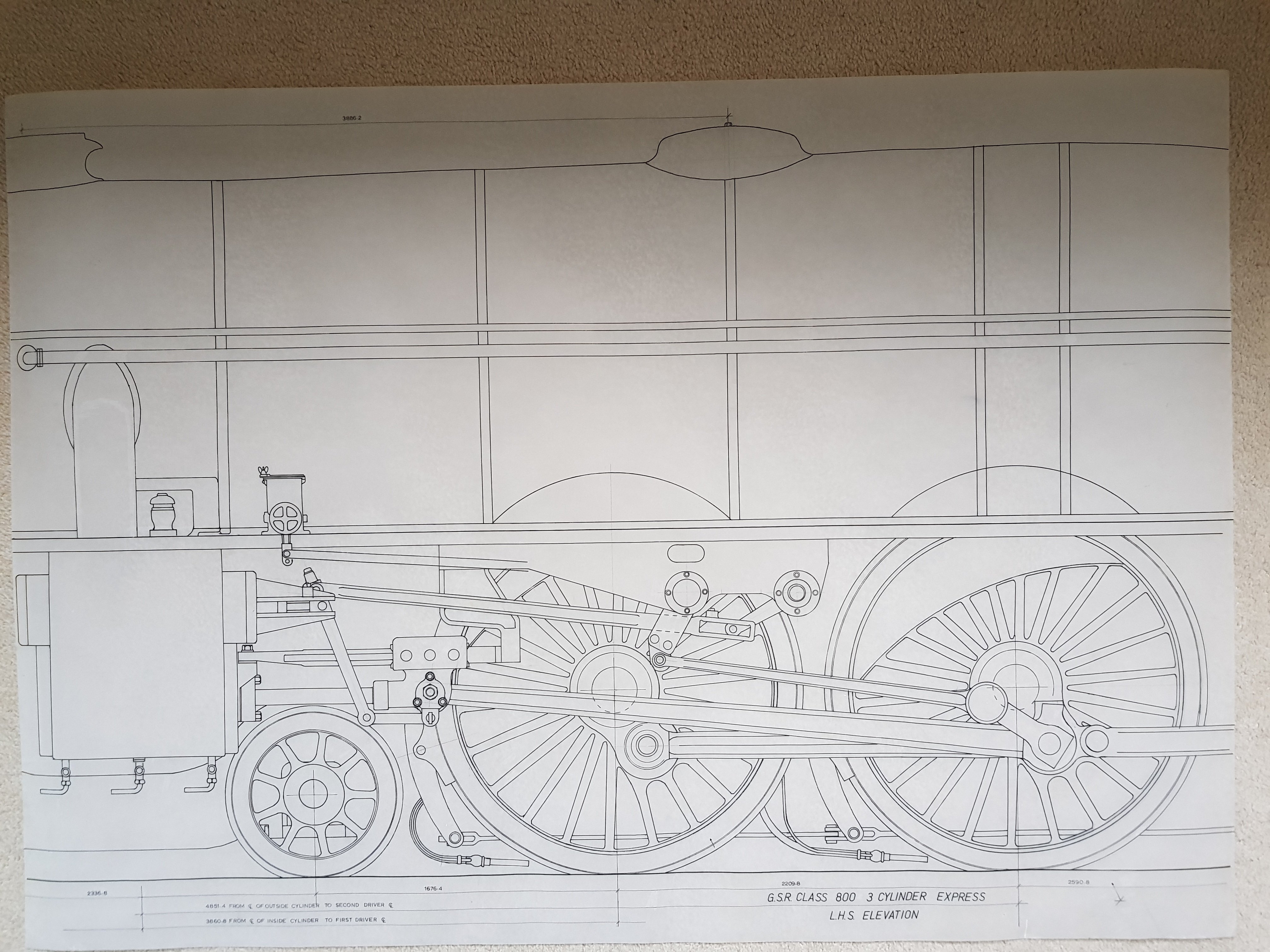
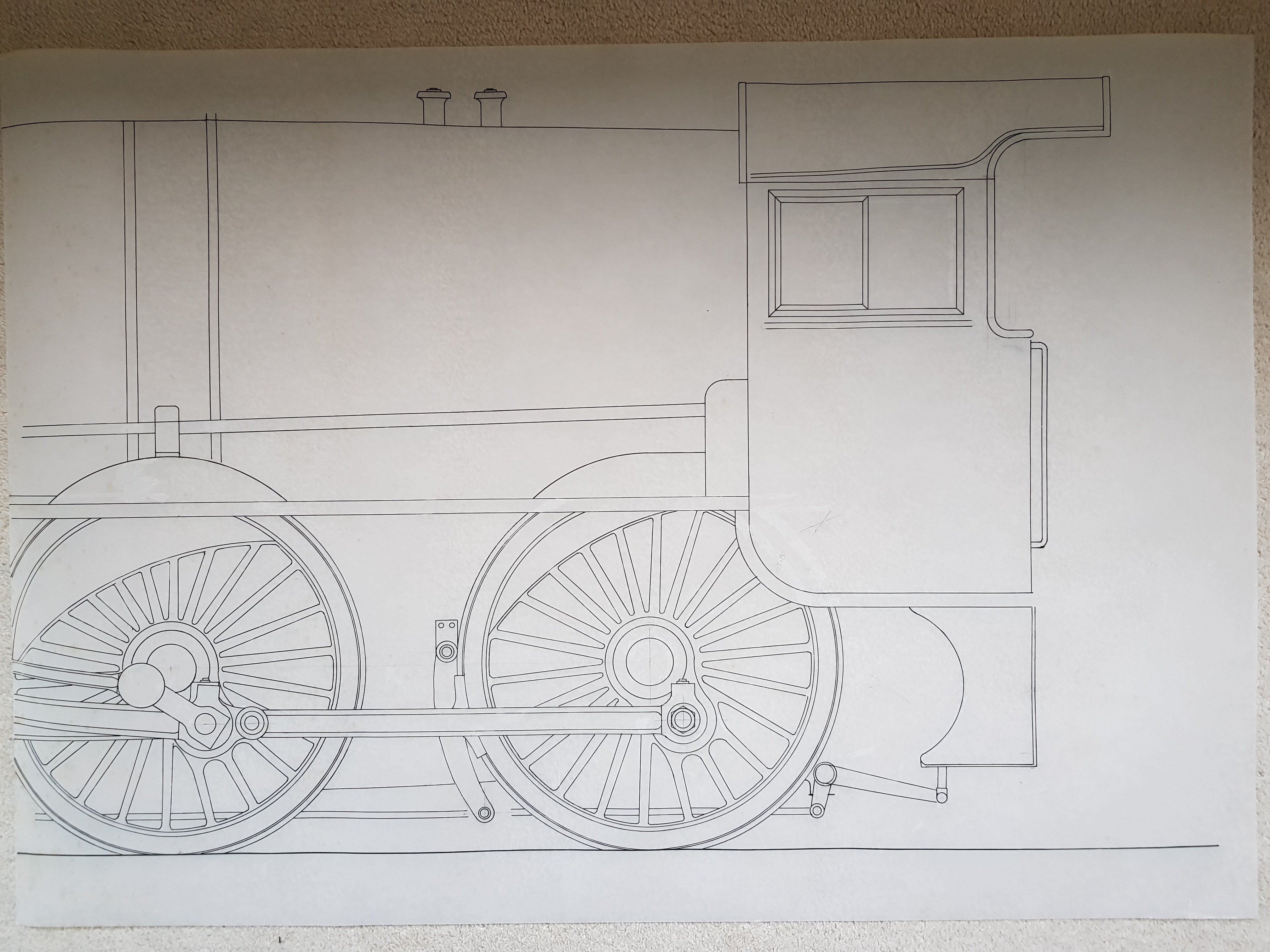
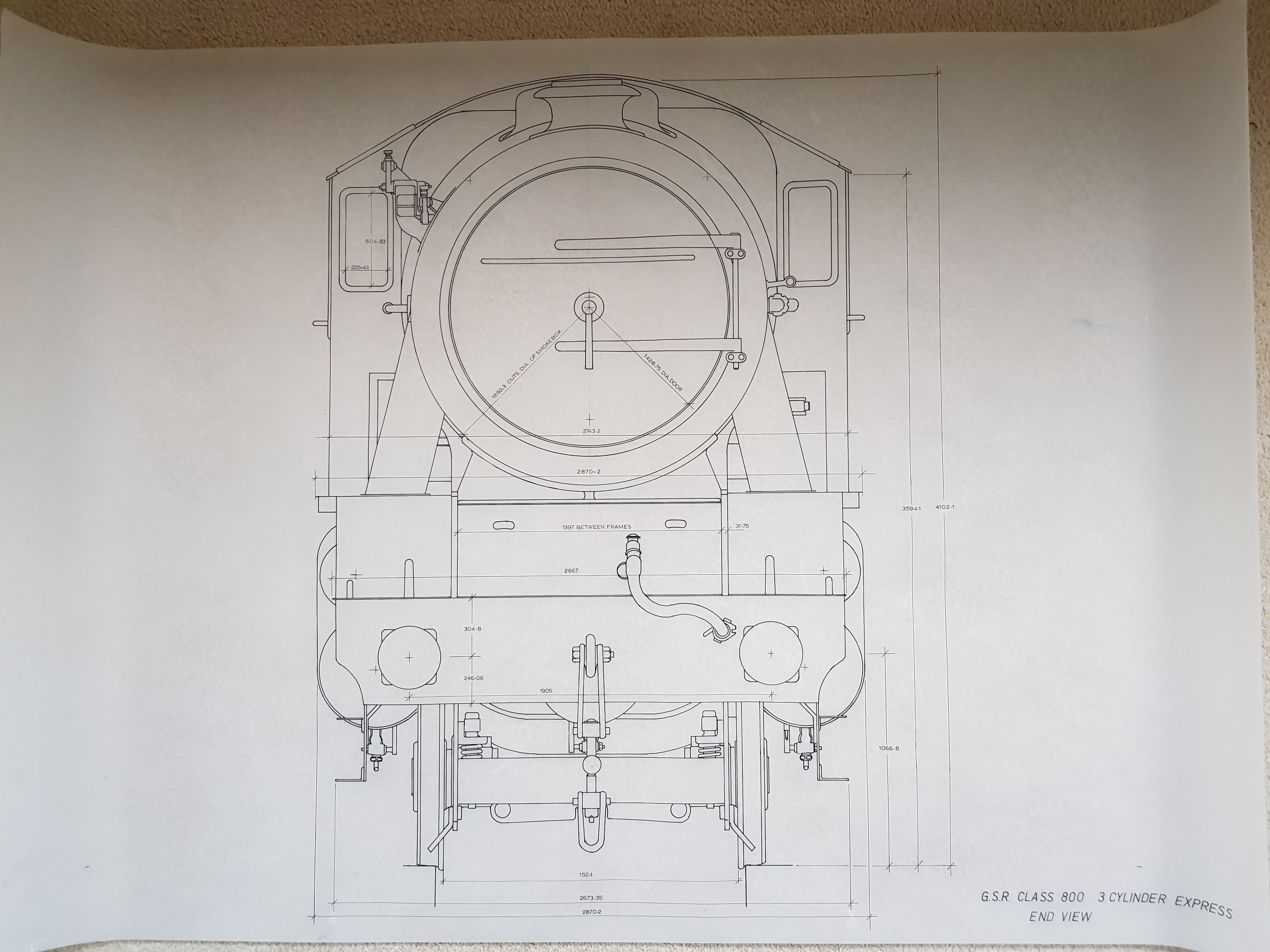
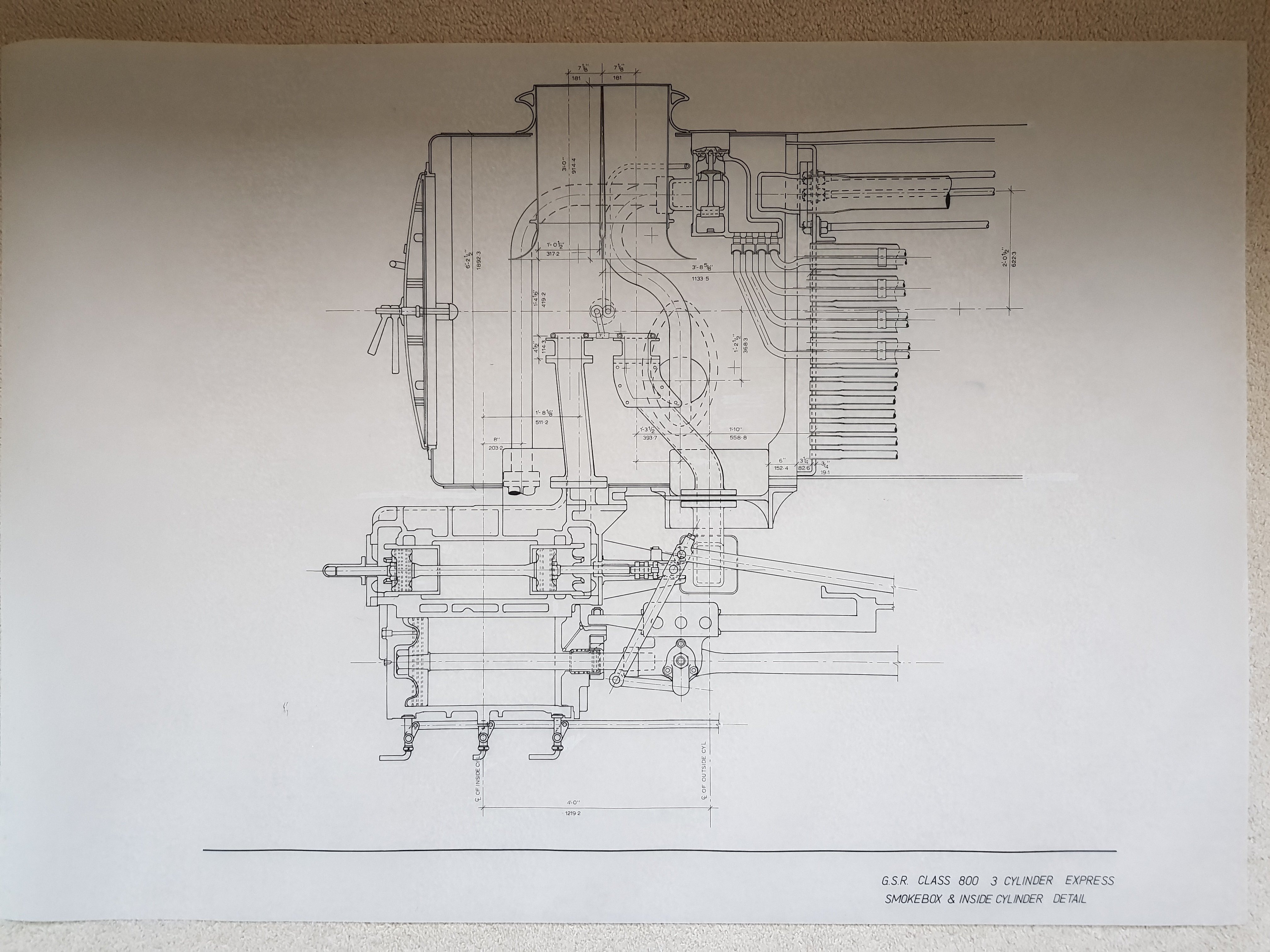
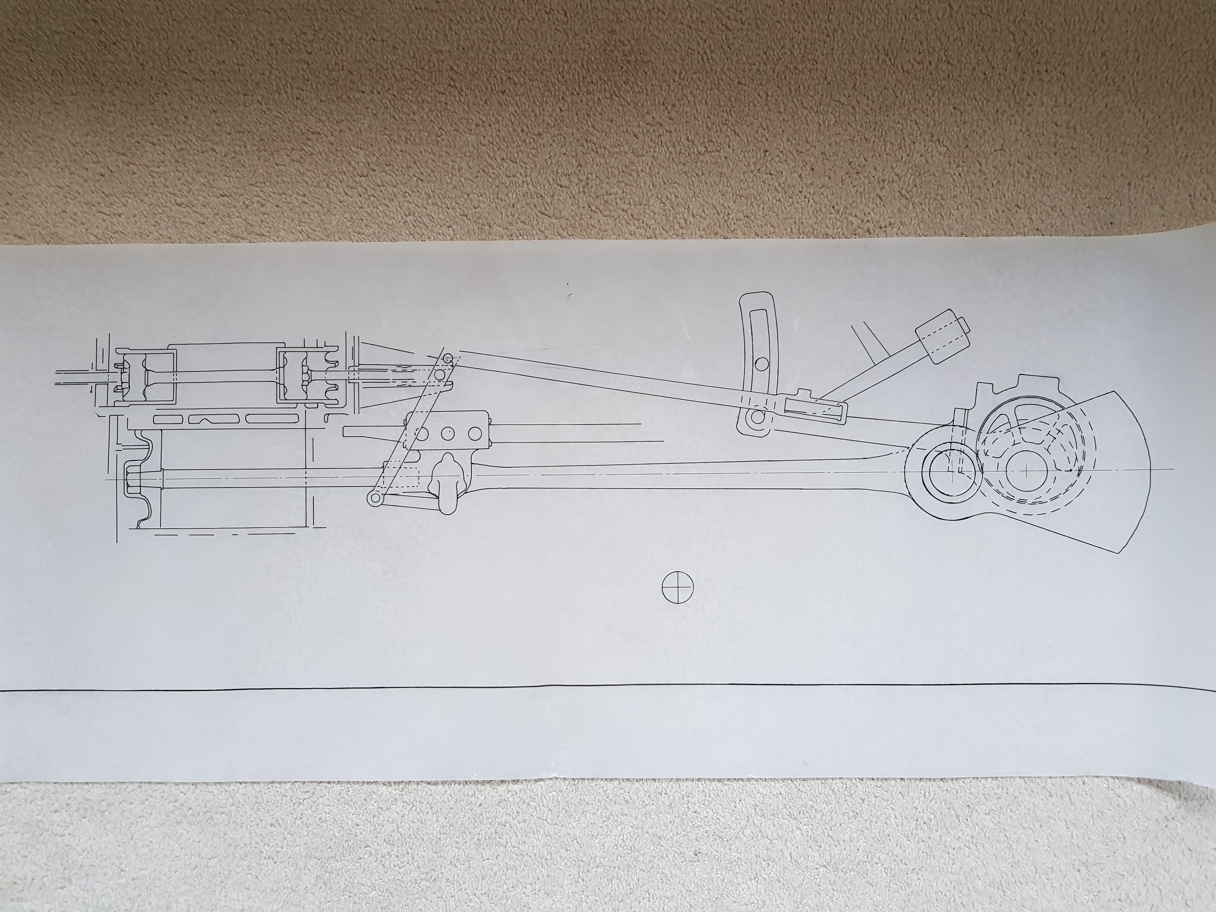
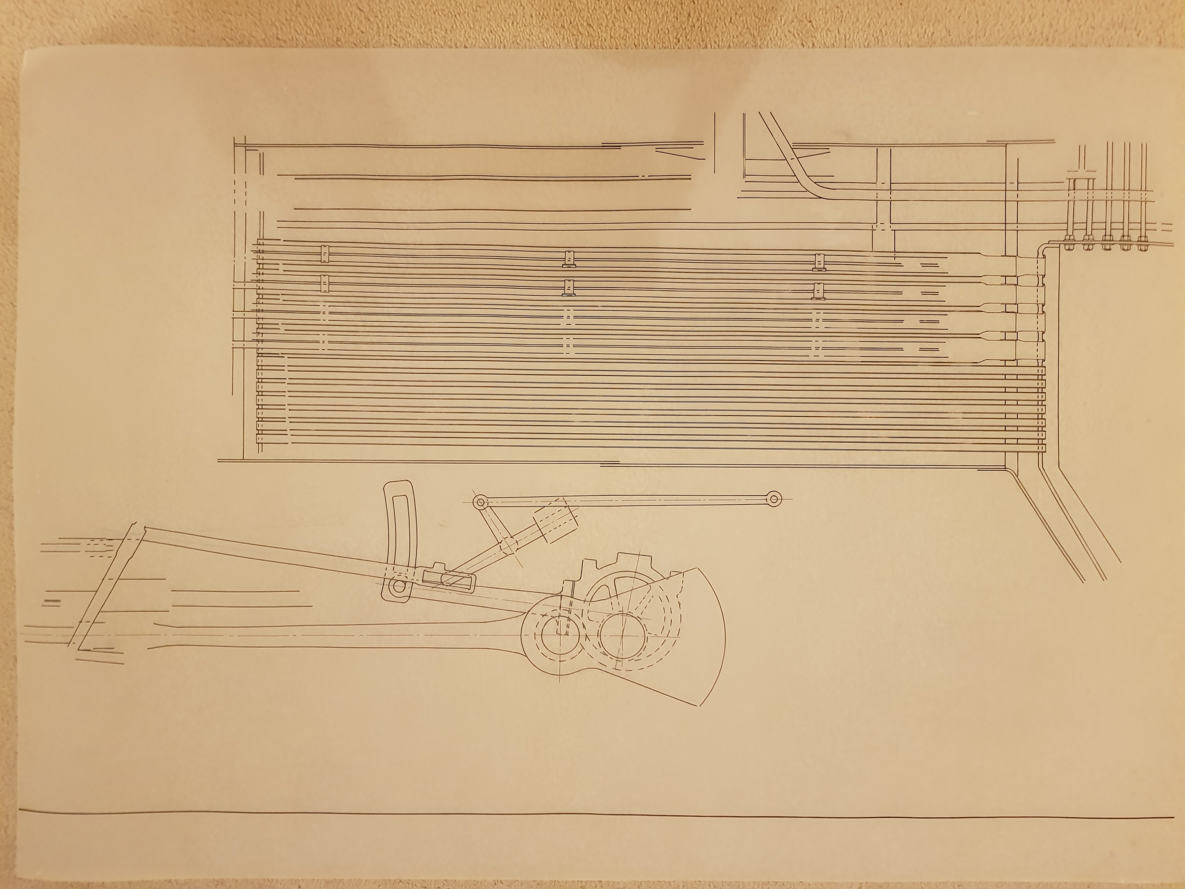
Looking at the locomotive drawings etc in Resources prompted me to dig out the drawings I developed for the Class 800 from the original. These were done the old way of pen and ink on the drawing board, as CAD was in it's infancy and cost more that a small house to buy, never mind the computer cost. I worked from the original drawing I requested from IE many moons ago. The drawing was taped to the board, and A1 negatives created from it - there is a huge amount of information on that old drawing, so I took the layers off and made multiple drawings to clarify the detail. I don't have access to the resources section, but perhaps it's a little early yet as I need to get these scanned / digitised with the intention of bringing them into CAD. Once they are scanned, perhaps they can be added to the resources section and will be available if anyone wants a copy. When brought into CAD, we will have more definitive drawings to work with. ** Edit Should have added this one as well. It is incomplete but when put with the drawing on the smokebox it provides the detail of the inside motion and fire tubes back to the boiler. Ken .
- 12 replies
-
- 12
-

-

-

-
That came up really well. Well done Sir! Ken
-
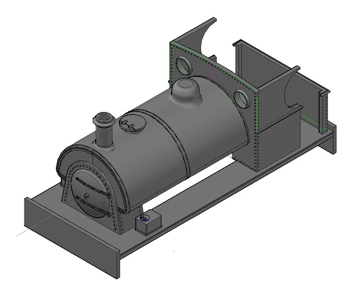
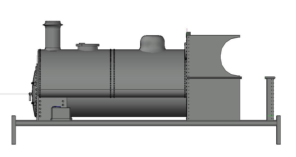
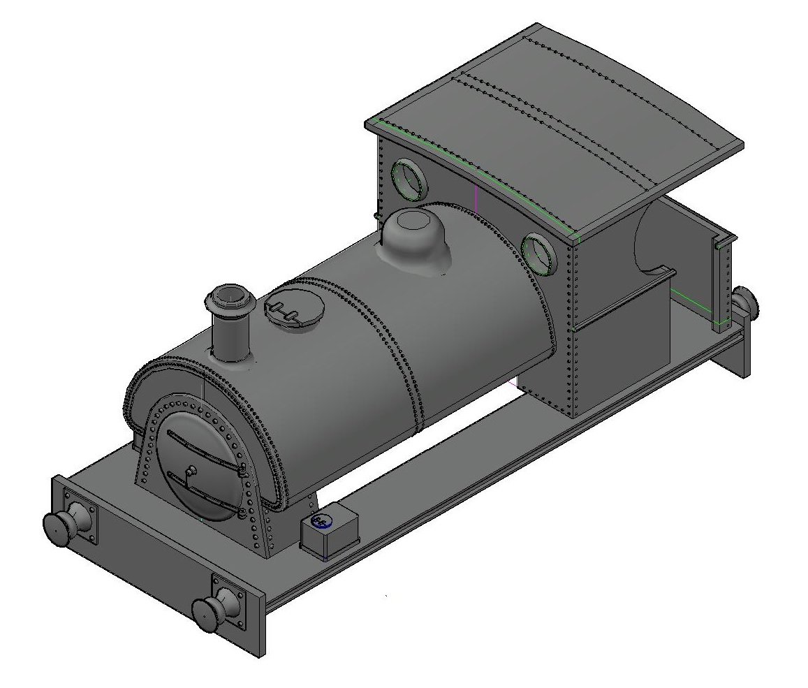
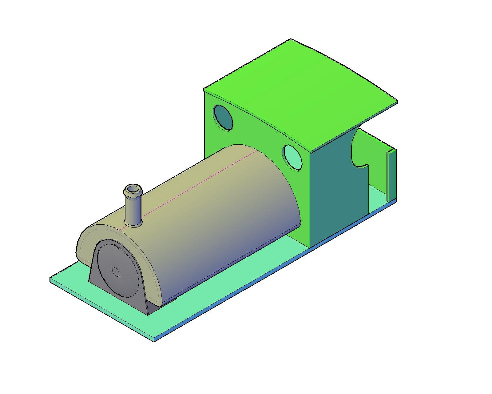
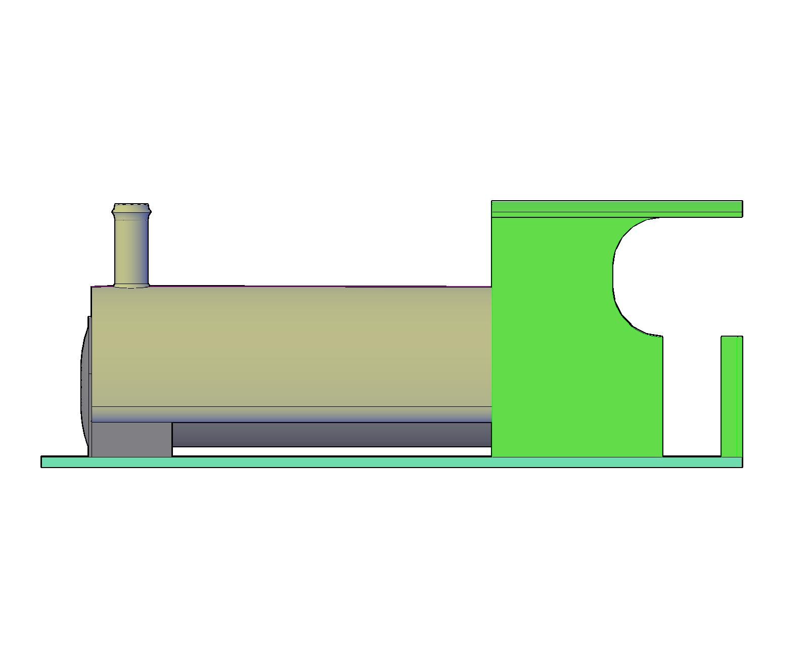
I have a lot of experience with 2D CAD as I use for work (the real work!), and downloaded the full version of AutoCAD on trial to try the 3D version. The commands are generally the same with the addition of stretching or providing depth to shapes. In a few hours this evening, I have come up with this as a first project. Looks basic enough so far, however it is possible to build up the elements in stages and bring them together. Boiler elements are dark grey, tank and chimney are light grey, cab elements are mid green, and by chance the footplate is in eau de nil. By doing it this way, it will be possible to deconstruct the model into component parts and print as a kit and assemble as one would a standard kit - it would be necessary to provide some additional material to line up parts etc. However given the size of this thing, it probably could be printed as a single unit. As to the costs - the eye watering bit is the cost of AutoCAD (€260 per month!), the DLP printer noted above is c. € 500 and resin is about €75 per litre. I terms of turning out models, what would make life much easier would be proper dimensioned drawings of the prototype (perhaps IE could help here?) which would reduce drawing time. At present, I'm trying to measure from an existing model, which is not really an accurate way of doing things! If I can convince the accountant that my CAD package is out of date and I need to upgrade, "there may be trouble ahead". (oo00OO...now why would an engineering company need a 3D printer?.....) Answers on a post card to the usual address.... Ken
-
This is an area that is piquing my interest at the moment. I follow this guy on Youtube & he recently demonstrated a DLP (Digital Light Processing) 3D printer The results look excellent, however the size of model being produced would be quite small - not an issue if you were to make a series of parts and assemble as a kit afterwards. This printer appears to be selling for less than €500 which (for those of us who remember) was the cost of inkjet printers not so long ago! Like inkjet though, it appears the resin is where the cost is c.€ 75 per litre which may make things a little expensive. It may not be the quality of RTR tooling, however for small and rarer items, this is starting to look a little more economic. Ken
-
I use an ope size of 46mm wide by 64mm to top of arch - this seems to fit all locos & wagons I have. It also fits the arch sets available from scalescenes which I use to detail the building. That's a really nice photo and would make an excellent model - huge amounts of detail and would set back nicely into the board with a low relief backscene Where was it taken? Ken
-
The signage is superb and really adds realism to the scenes. Well done Sir! Ken
-
Hello David, I would concur with Eoin; leave as is? The general consensus on antique and vintage is to keep it as original as possible. Where repairs are required there are two schools of thought - blend in the repair, or highlight it to show what is original vs new. I'm in the "blend in" camp, as I believe items were made to the highest standard and the maker would want them to look as good as possible. You have a good-un there, and those that know will appreciate for what it is, those that don't, wont care either way. Ken
-
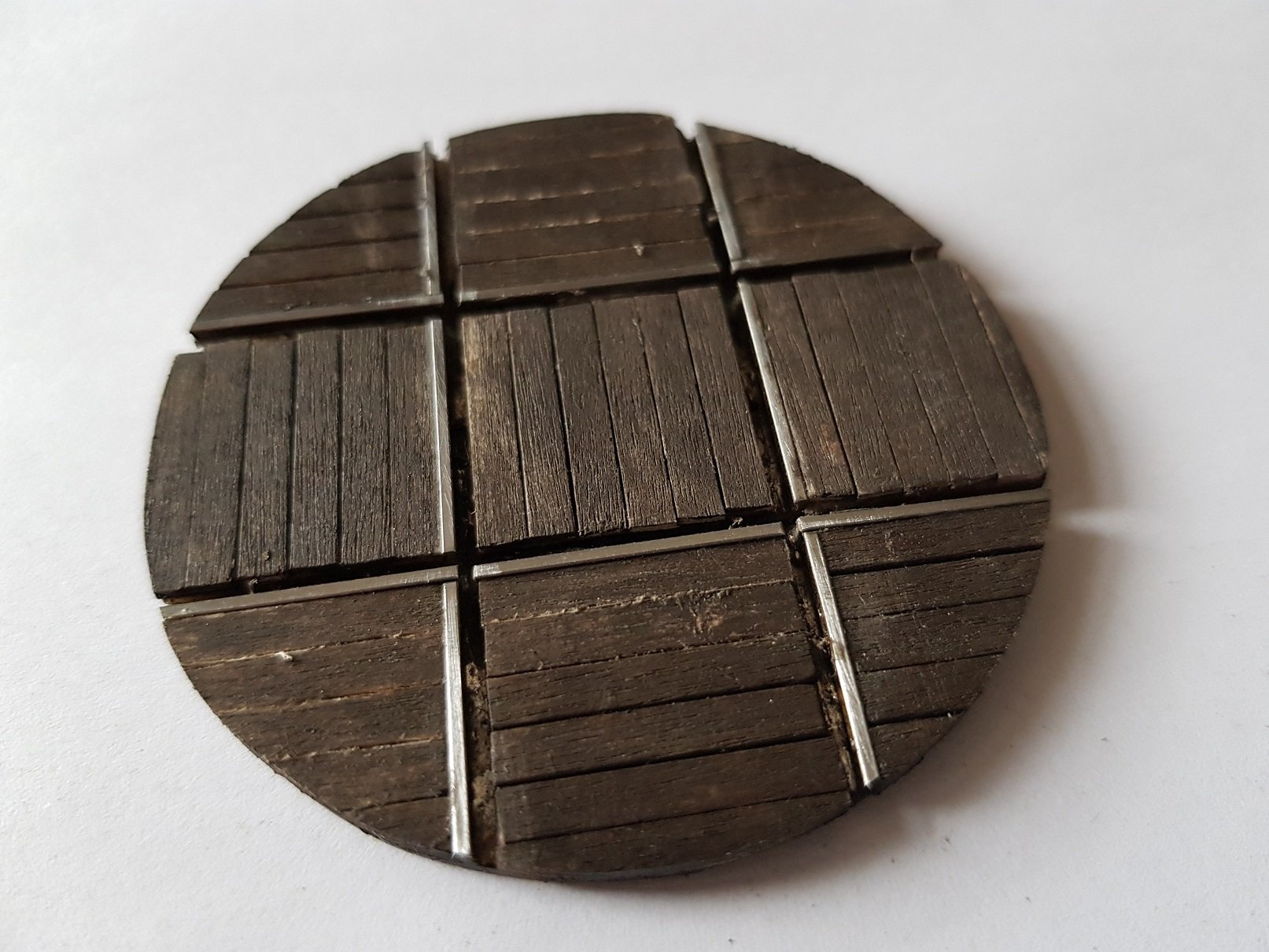
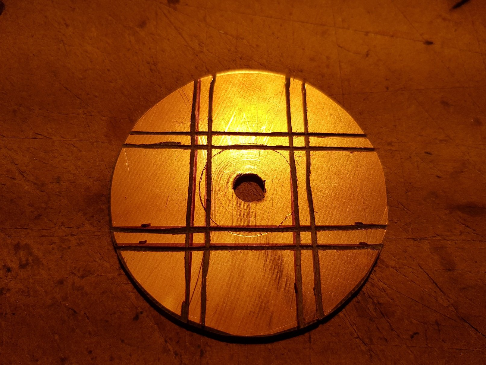
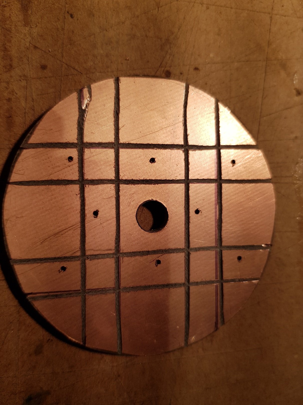
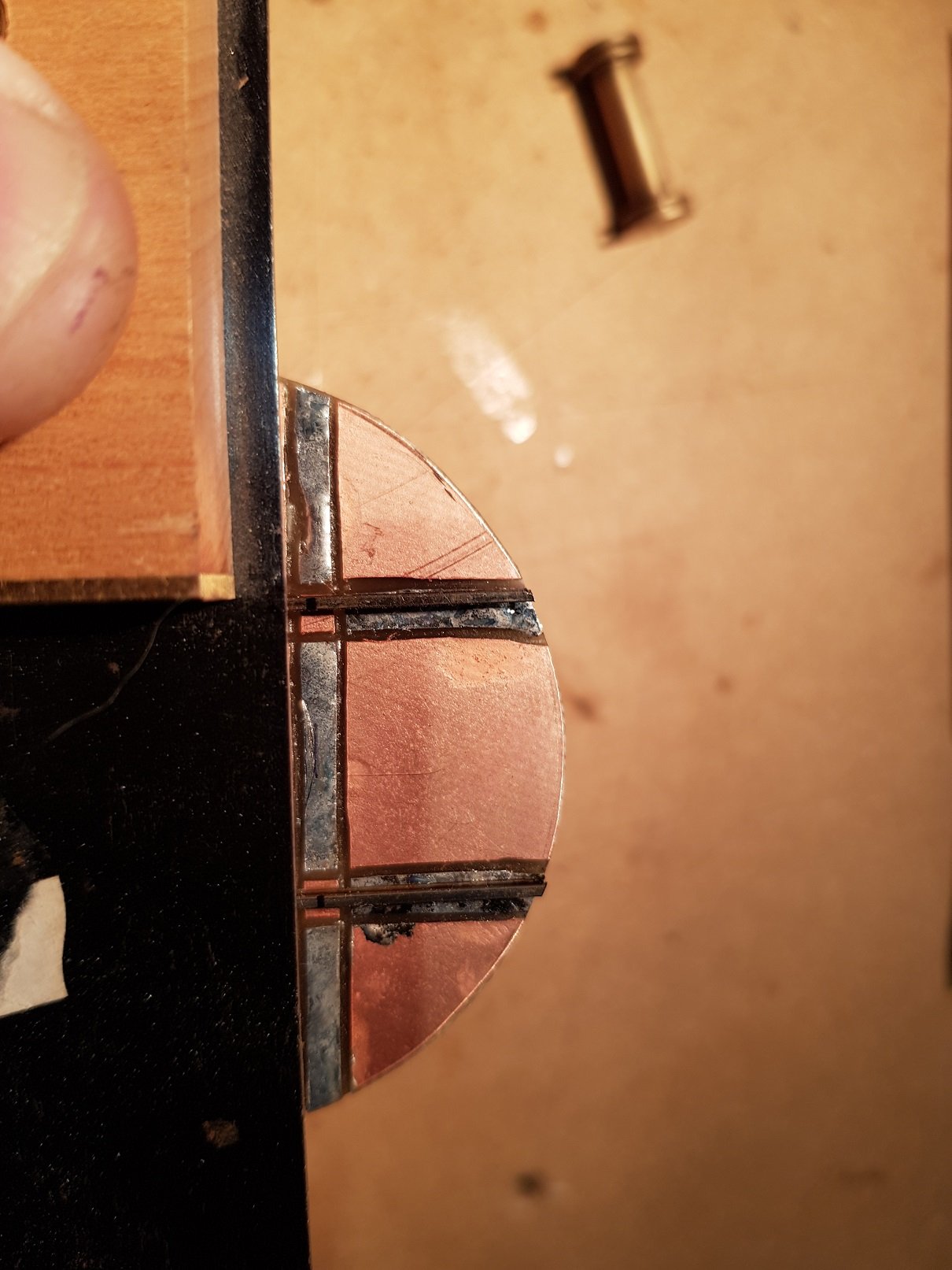
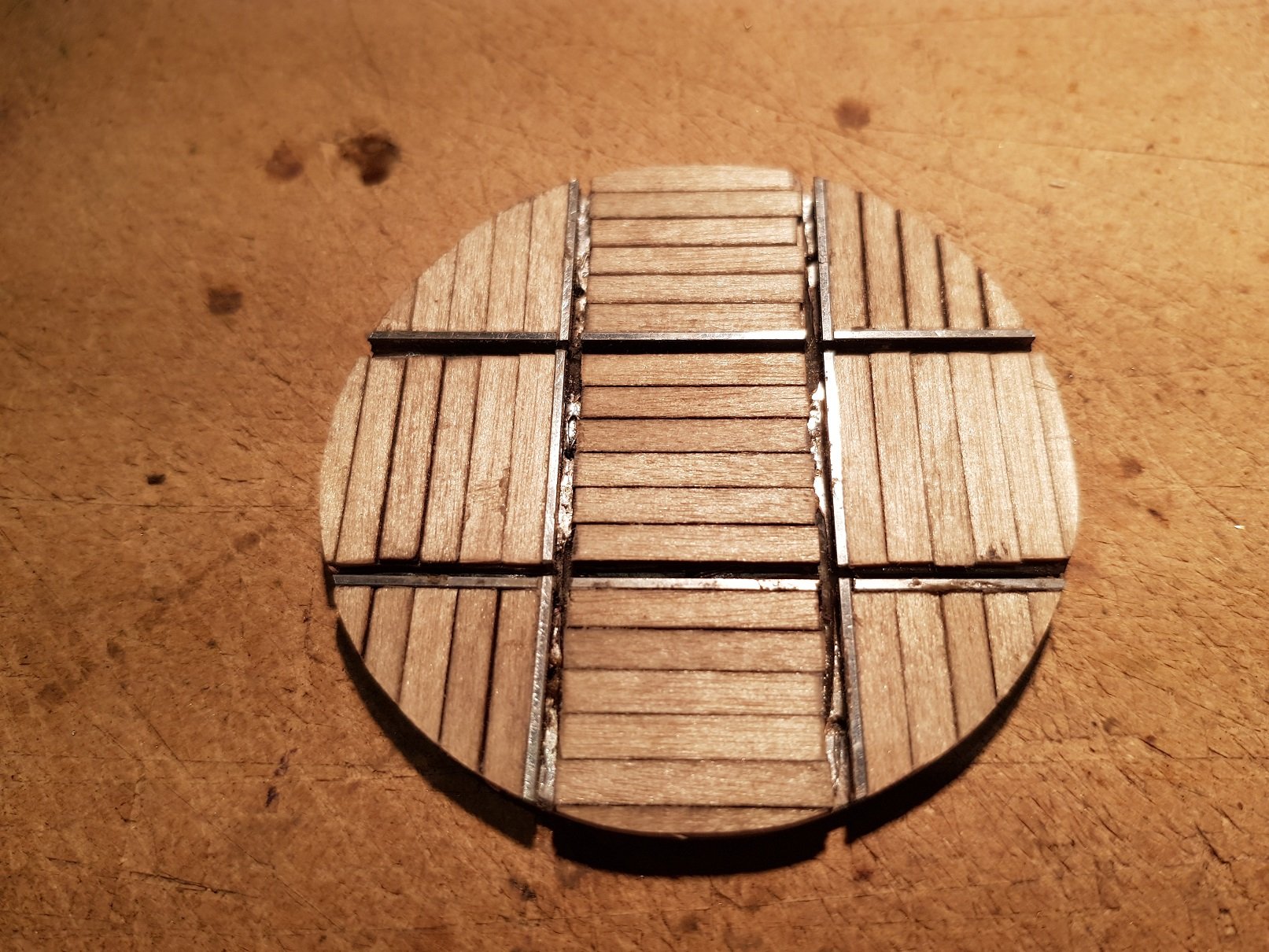
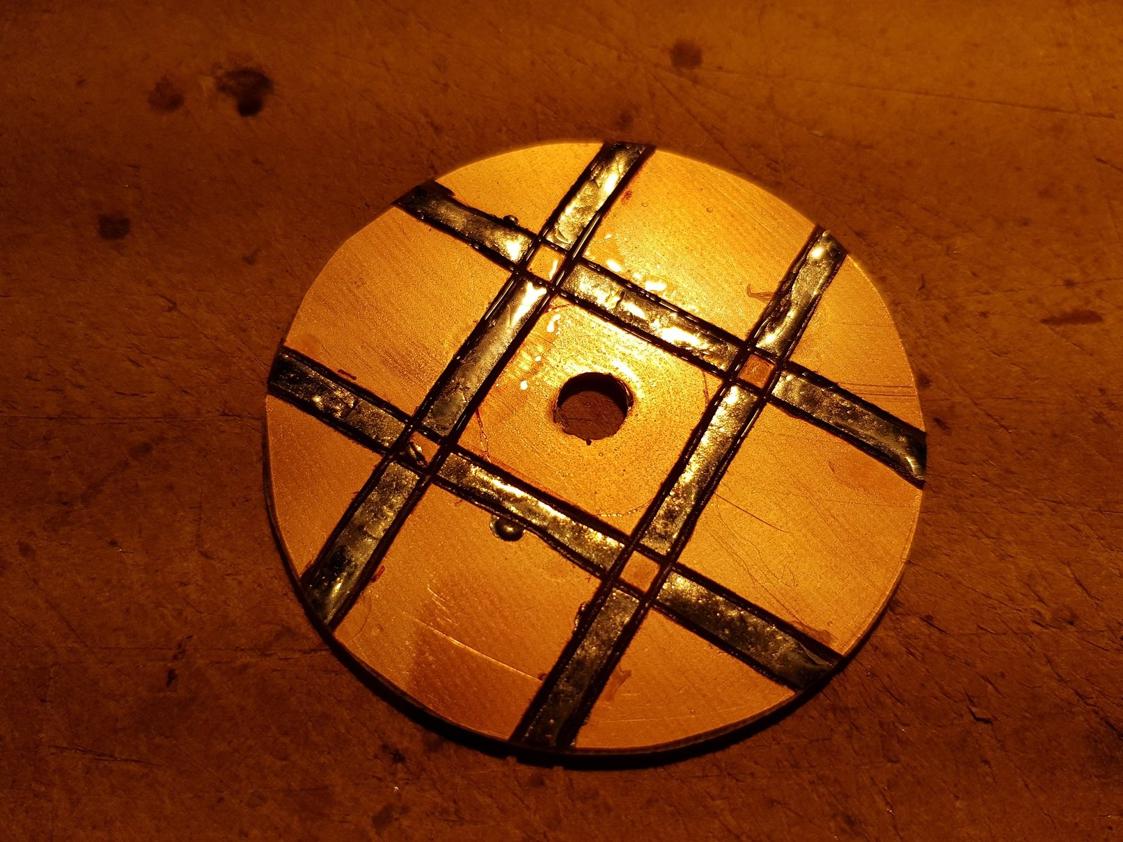
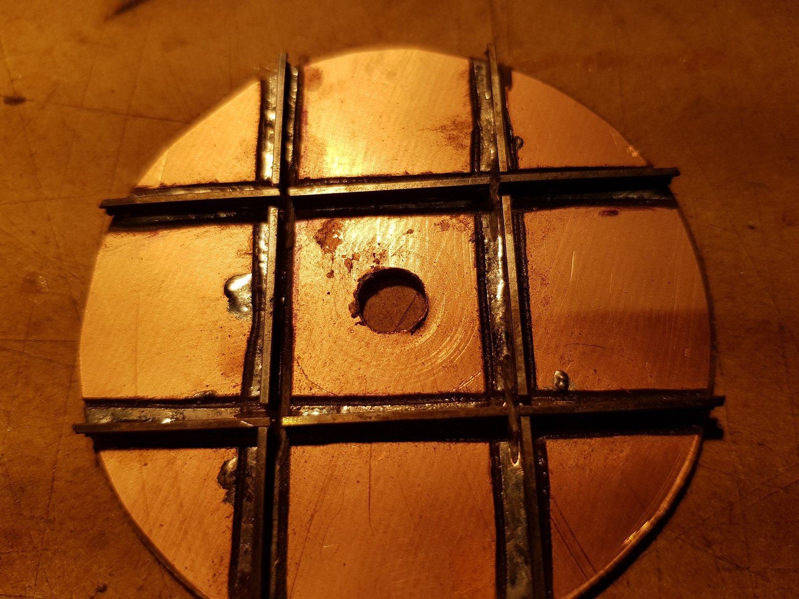
Hello All, As part of the Port Cumtha layout, I needed to make two wagon turntables. I settled on using the Copperclad method as it is easier to fix and space the rails. Don't really know if this is a tutorial, perhaps a bit more of "this is how I did it", but here goes. I started by cutting out a 60mm disk from a PCB sheet with a hole saw and marked a circle which is 21mm diameter to indicate the position of the track. Electrical conductivity needs to be addressed, so I marked out tracks where the rails would be and scored the lines with a cutting disk just to break the copper into areas. The main areas were tinned with solder, avoiding the crossing locations Rails were tinned with a little solder and fixed down in place using the 21mm gauges. The rails can now be trimmed at the edge of the disk so they don't catch. The crossing rail is squared with the main rail, and crossing points marked to be cut with the cutting disk. The rails don't appear to line up with the tinned lines on the disc, but this doesn't really matter as long as the rail has contact with the solder on the track below and doesn't cross onto another section of copper. The two crossing rails are added after cutting the primary rails. I set in the first rail, then used the gauges to mark where the second rail would cross, and then cut the second rail. Once all four rails are in place, judicious use of the cutting disk is needed to trim the inside rails to allow the wheel flanges pass. Top left cut is a little loose as some fettling of the groove is needed to ensure the correct back to back gap on the rails. This can be filled with solder later if required - this is a close up, and at a distance, the gap will not really be noticeable, so I'll see how it looks later. As these turntables will be live, some form of electrical connection is needed. I decided to score the back, similar to the top and drill fine holes through for droppers. Some fine wire was tinned and passed through and soldered to the copper below. I propose to use light springs & perhaps small ball bearings (or similar) located under the turntable lined up to contact the copper area, which will allow power to the relevant sections of track. I still need to resolve how power will be supplied to ensure no shorting, so it may be an either / or solution with locomotives only able to travel in one direction at a time - the perpendicular section of track will be dead when trains pass through. Trimmed sleepers were added in two layers, set at 90 deg to each other, to provide strength, and to build up the height to the rail head. This was then trimmed on a sander in the workshop to provide that nice circle. The two layers provided the strength so that the smaller sections of sleeper would not break away when sanding. Painted sleepers to provide a finished look, and now for installation into the layout. Weathering and detailing will take the fresh look away and hopefully settle it into the layout. Power supplies & surround to be completed. I'll post a picture, once installed in the layout. Hopefully this will help someone in the future, or perhaps just provide some reading on a quiet evening. Regards, Ken
- 2 replies
-
- 12
-
-
-
For building finishes, I use Scalescenes https://scalescenes.com/ . Both OO and N gauge covered. They have a few freebies, so you can have a go without any cost! I have bought and built a few of the buildings and they are both good value and give very realistic results with minimal input - instructions are good, however it is important to get the card thickness right. For the heavy card, I get mounting board from the local craft shop (c. €10) for an A1 sheet, however it does go a long way. I get good use from the "Scratchbuilders yard", as they provide, brick, stone, timber finishes, roof tiles, etc which are good value and you can print off as many times as you like. Brief note - use an inkjet printer rather that laser, as the quality of print is generally better. Regards, Ken
-
Good attention to detail & finishing on the buildings. From the construction photos, it looks like considerable use of thin plywood for most of the building? I like the merits of plywood's strength, but I'm too lazy to go to the workshop to cut parts - I prefer to use card with printed templates from AutoCAD for structure, & printed finishes from Scalescenes. Is the layout constructed in such a way as to make it transportable?
-
That is an absolutely stunning layout - well done. The buildings are incredible and very accurate - was this through site photos, or good use of google? Very impressive! Ken
-
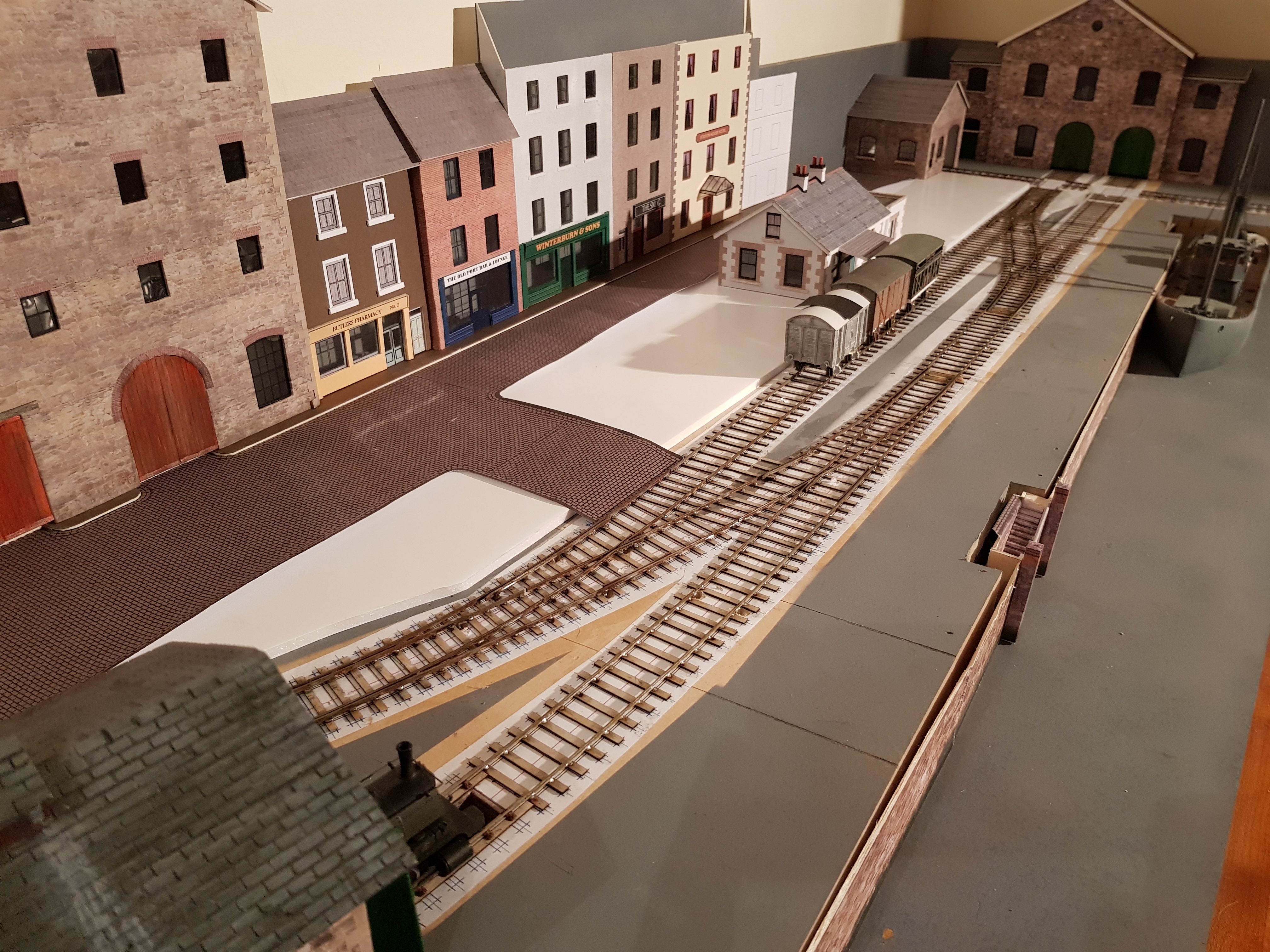
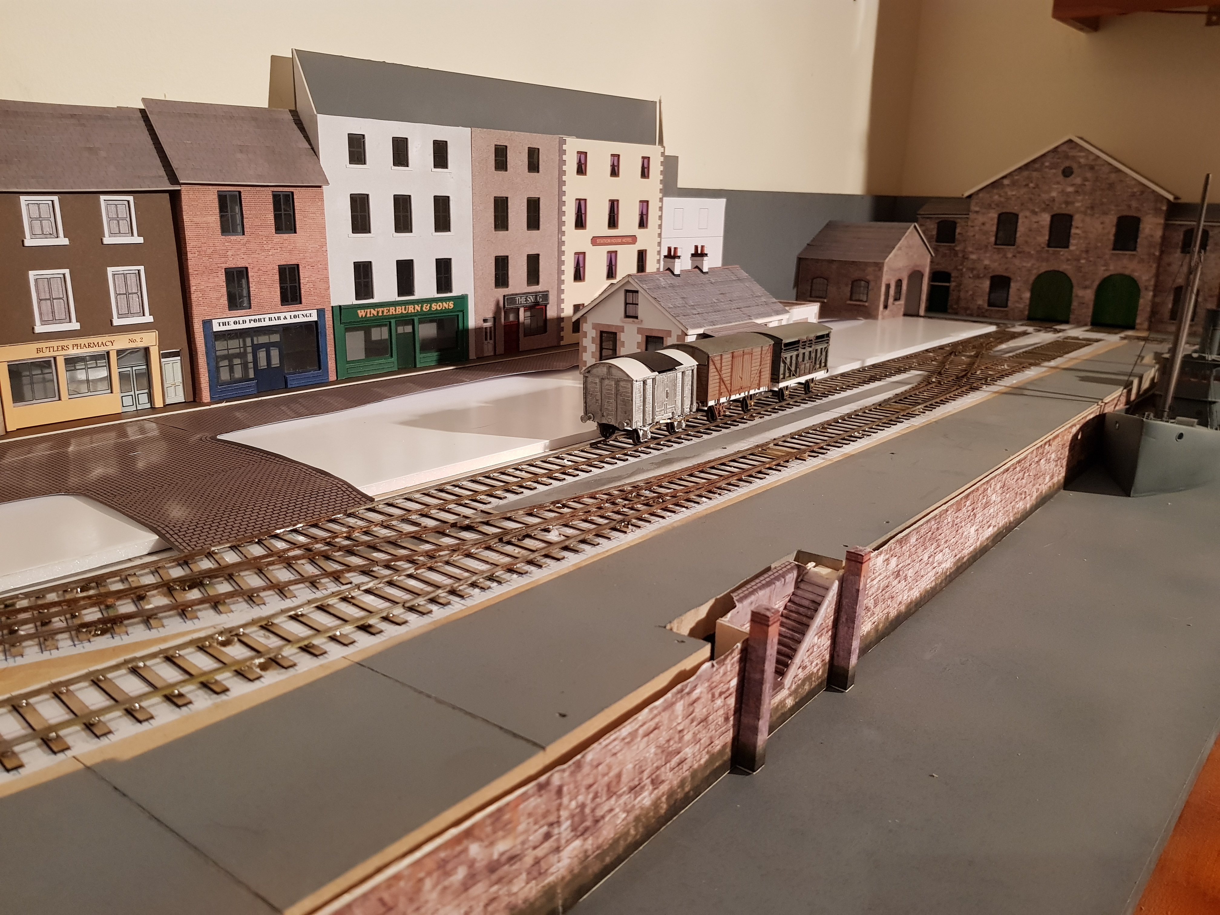
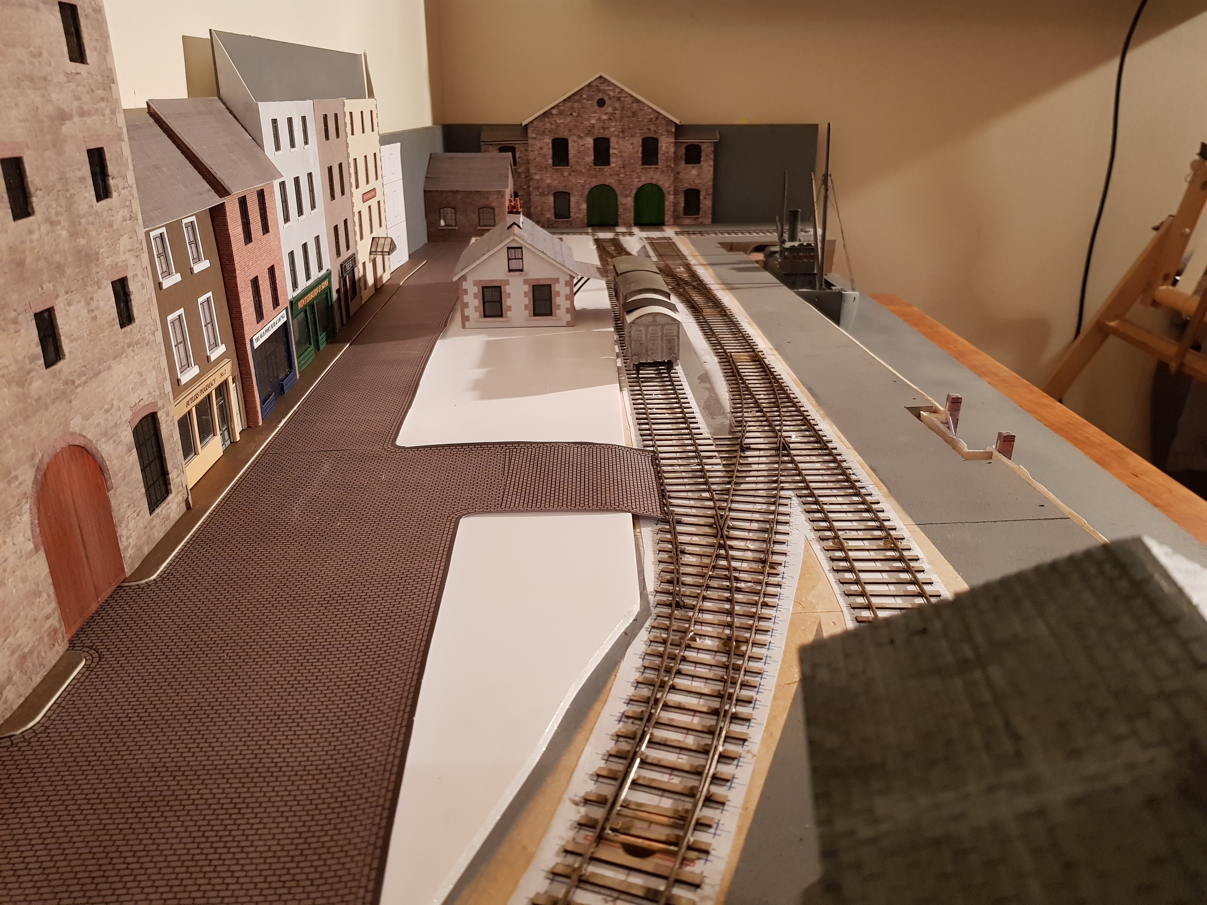
That track was not going to fix itself, so I took my brave pills, put on the man pants and went at it! The copper clad PCB does make the tie rods etc easier to do, especially when you trim away some of the copper at the ends of the tie rod, so it runs under the rails without catching. One point is still giving some trouble with the switch rail not sitting against the stock rail properly - works fine in trailing direction, but de-rails in facing direction. Just needs a little fettling. The ash pit in front of the engine shed, needed longitudinal sleepers with plastic chairs added to the rail to fix and hold the rails. Looks better than the rivet construction, so I can see long days of cutting chairs to fit over the rivet and solder.... Lots of drop cables under the rails for power, however the wagon turntables are going to need a little thought to ensure I get power in both directions without shorts - not sure on that one yet; the gaps between rails may need to be generous to ensure I don't get a short across the tyre when crossing at 90 deg. Something else to fuss about later. It's really starting to come together though! The gauge and sleeper distances really looks well. BTW, the rust on the rails is real. The flux used to solder the rail to the rivet seems to remove any protection and rust starts to develop quickly - it will give an authentic look, except it will be necessary to keep the top of the rail clean for electrical conductivity purposes. Point motors and wiring to be done before I can set the base in more permanently. Regards, Ken
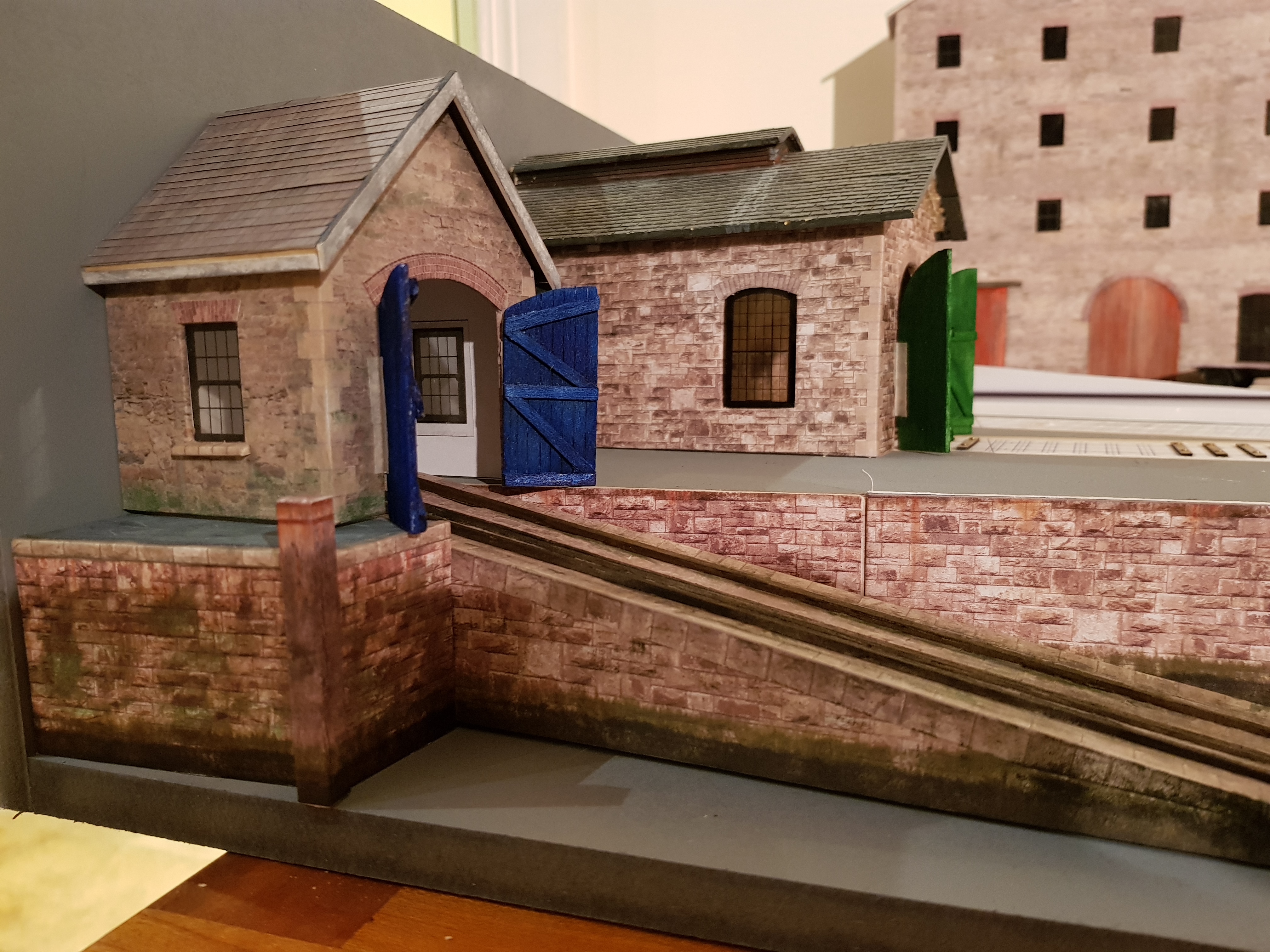
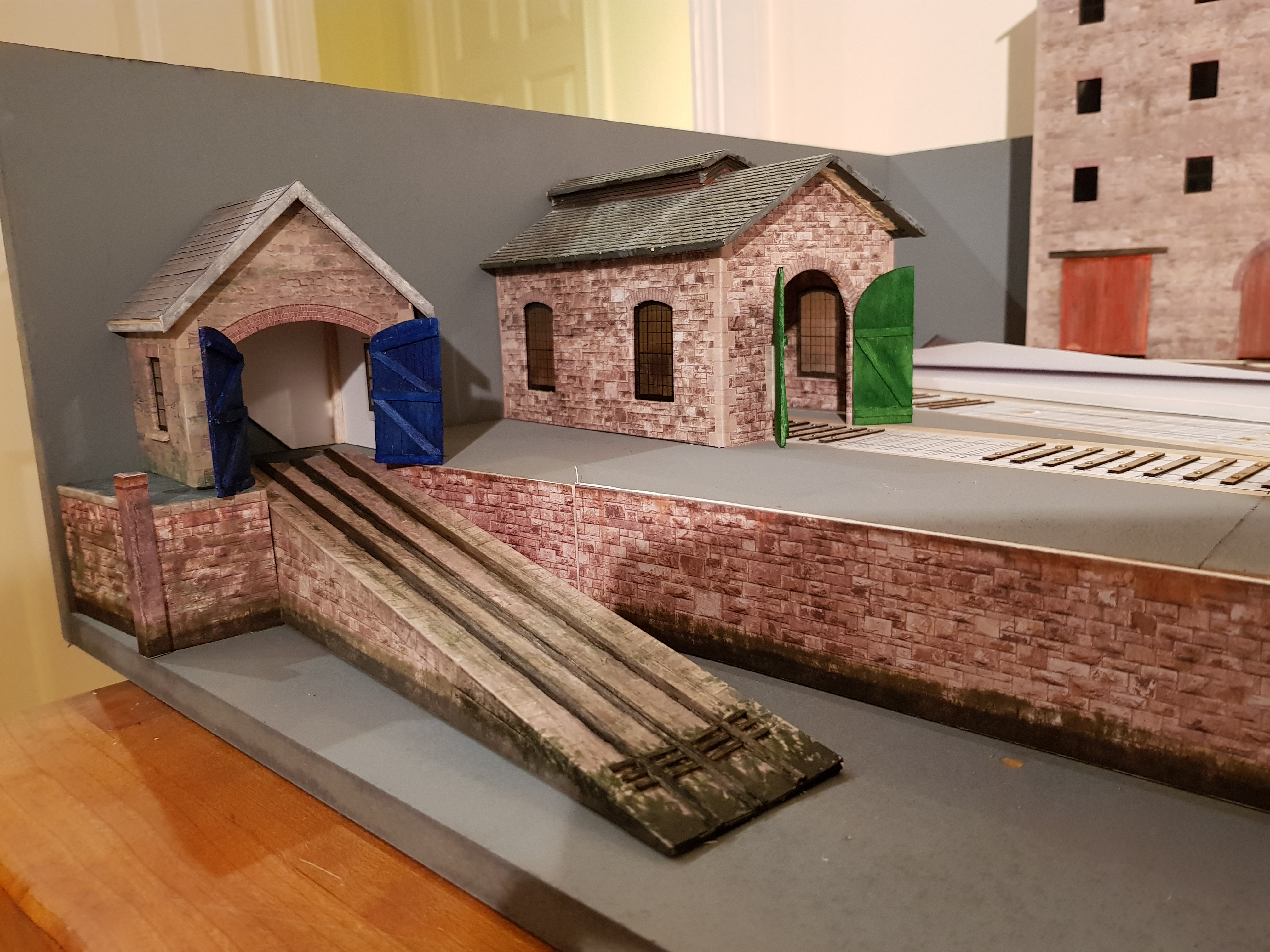
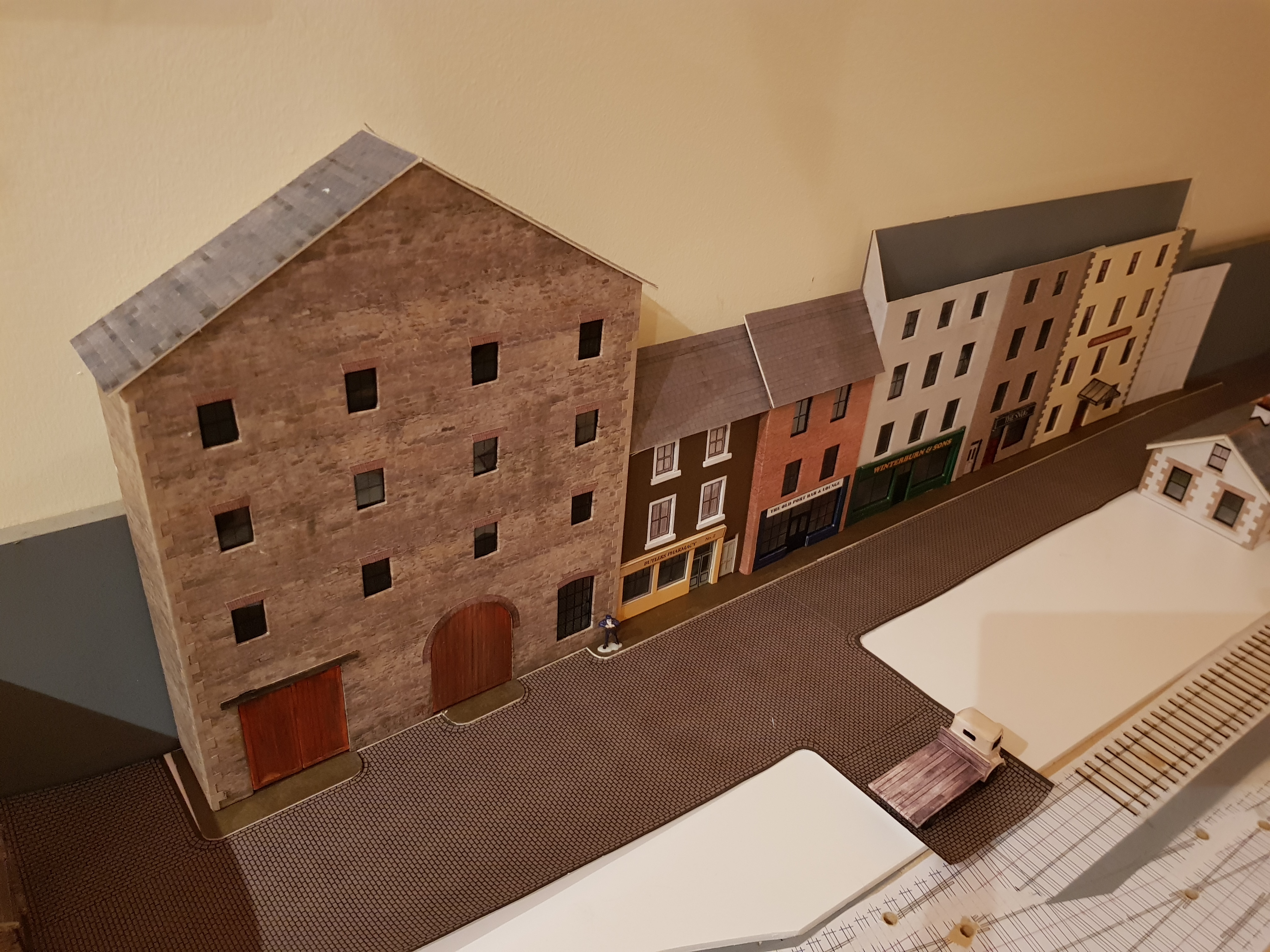
-
A little bit of progress. Painting the base boards and backs does make quite a difference. Lifeboat house is getting a little more detail and is nearly ready to dress into the layout properly - I'll probably leave it until I'm sure I don't need to lift the base again. Strand Street is starting to take shape - cobble lock street looks a bit better, but will need some distressing as it looks a bit fresh! Trying to add a little colour through door painting etc, otherwise it is all going to look a little drab!! Footpath is a little narrow - may need to bring it slightly forward. Window cills needed for the hotel to improve the look, as its a bit plain at the moment. Getting there & enjoying the journey........ Regards, Ken