KMCE
-
Posts
540 -
Joined
-
Last visited
-
Days Won
29
Content Type
Profiles
Forums
Events
Gallery
Blogs
Everything posted by KMCE
-
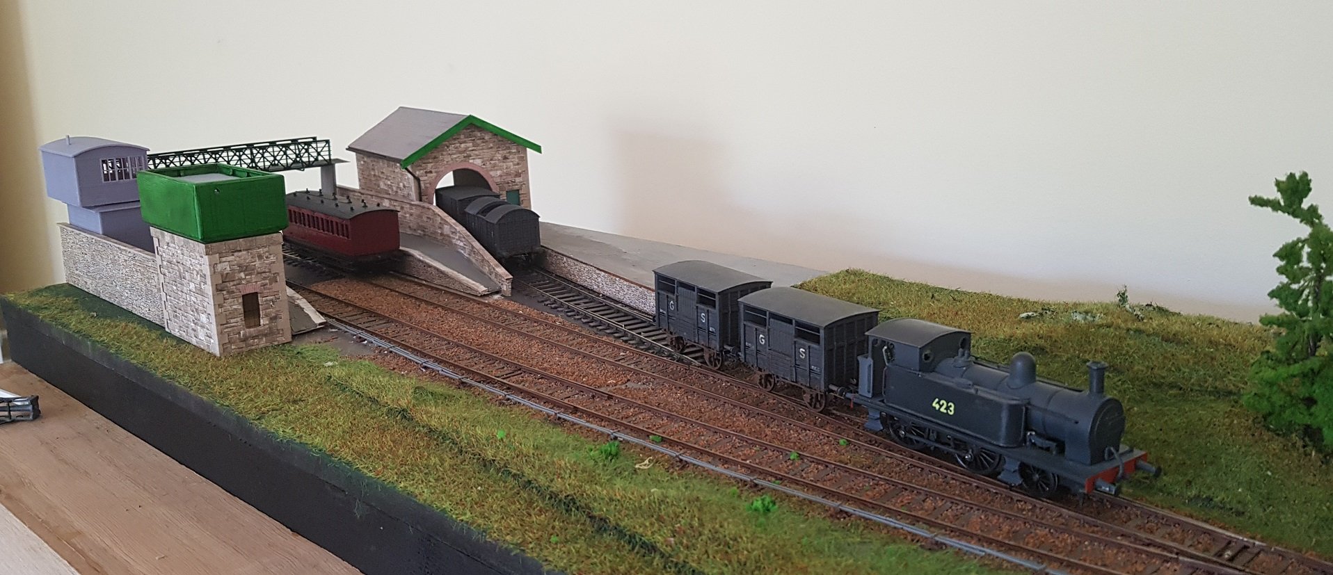
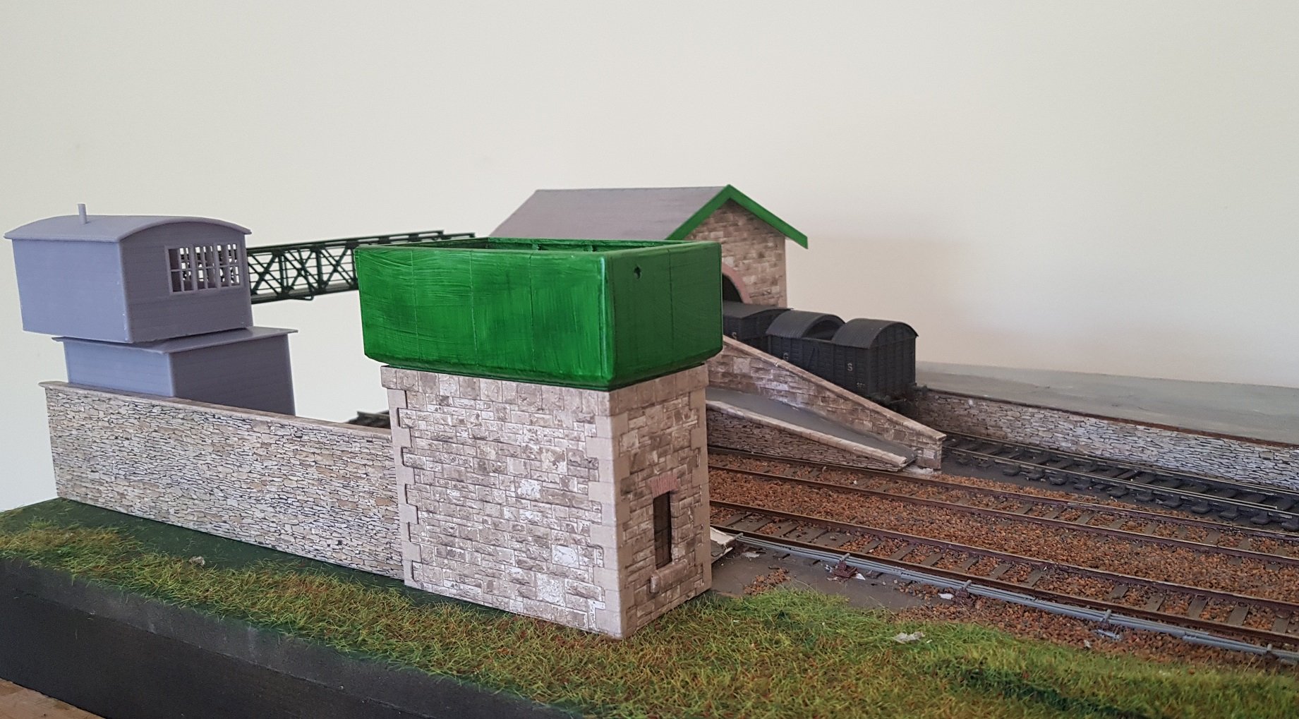
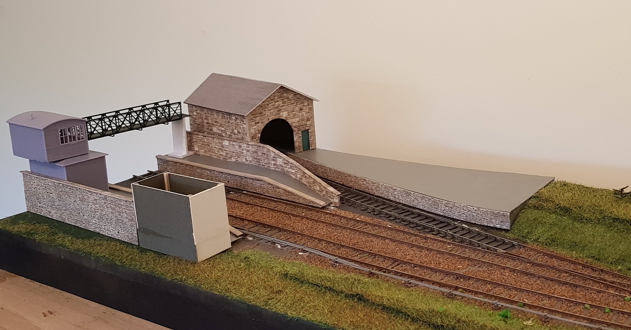
Little bit of progress over the weekend. Platforms have been surfaced & the goods platform fixed down with rail top fitted. Goods shed has bit more work done including fettling to get it to sit into the corner with the platform. Water tank was developed in CAD & printed - this one is based on the existing tank in Avoca amended in size to suit the layout. Building is card with built up quoins and tank support. Tank was primed & is brush painted (first coat) and needs to be further painted to improve the finish. Pipework, some colour and varnish for the water should finish it off. Existing grass at the front of layout to be removed before planting the main platforms in place which will then allow ballasting to be completed. Anyway - all for now. Ken

- 22 replies
-
- 13
-

-

-
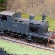
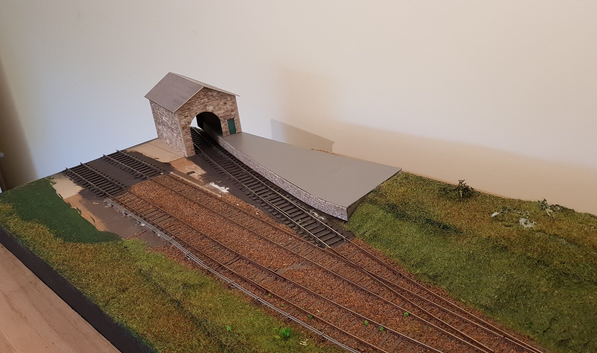
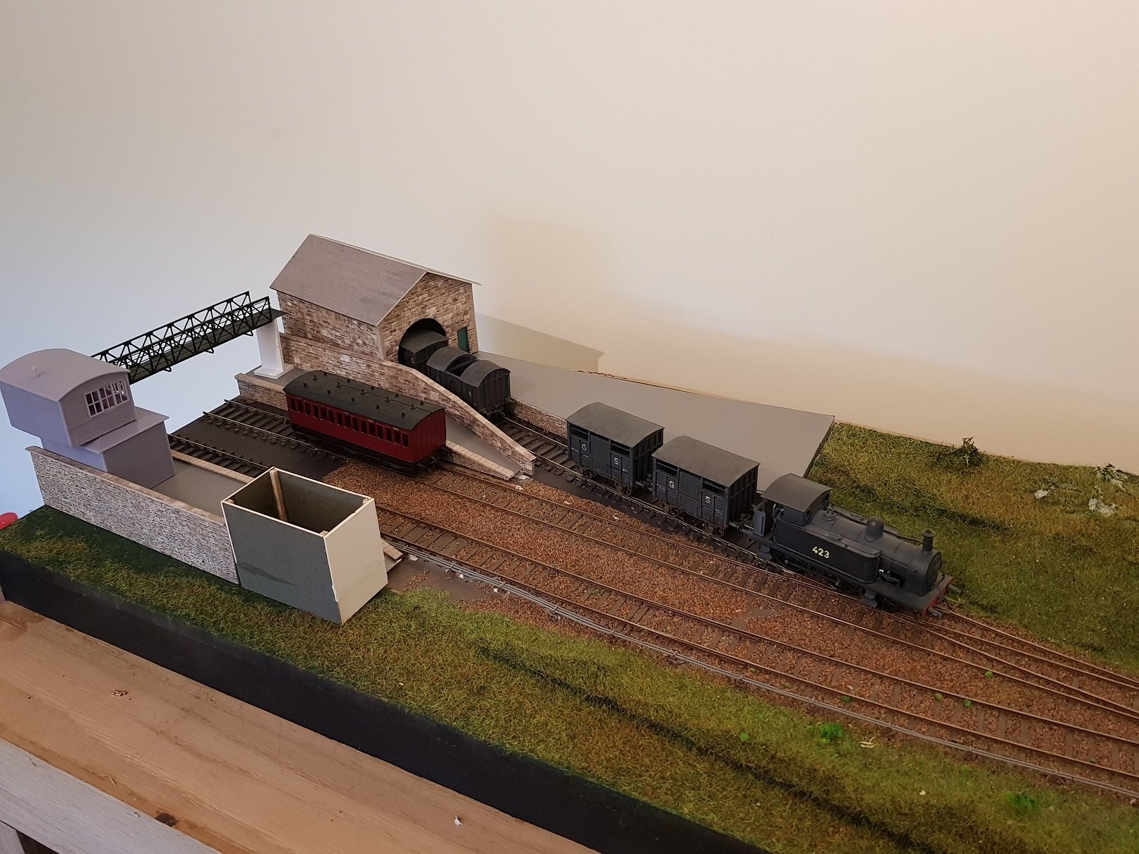
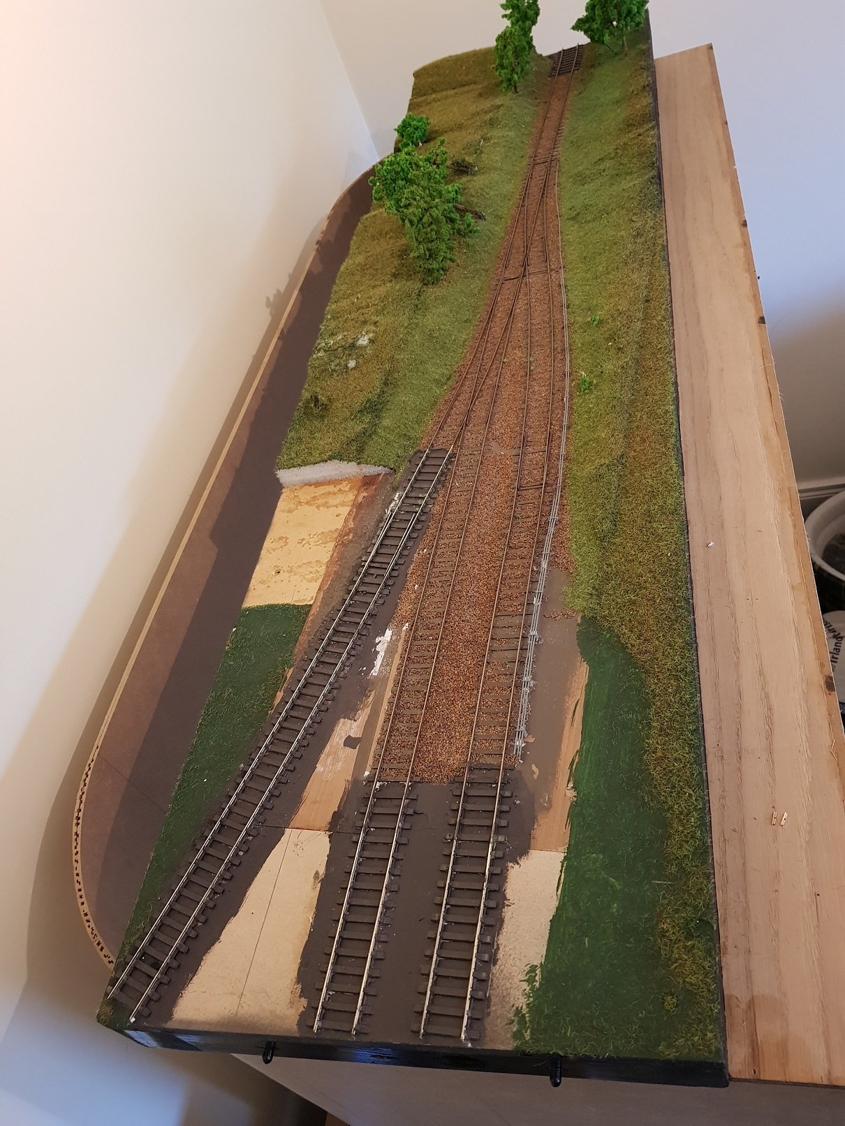
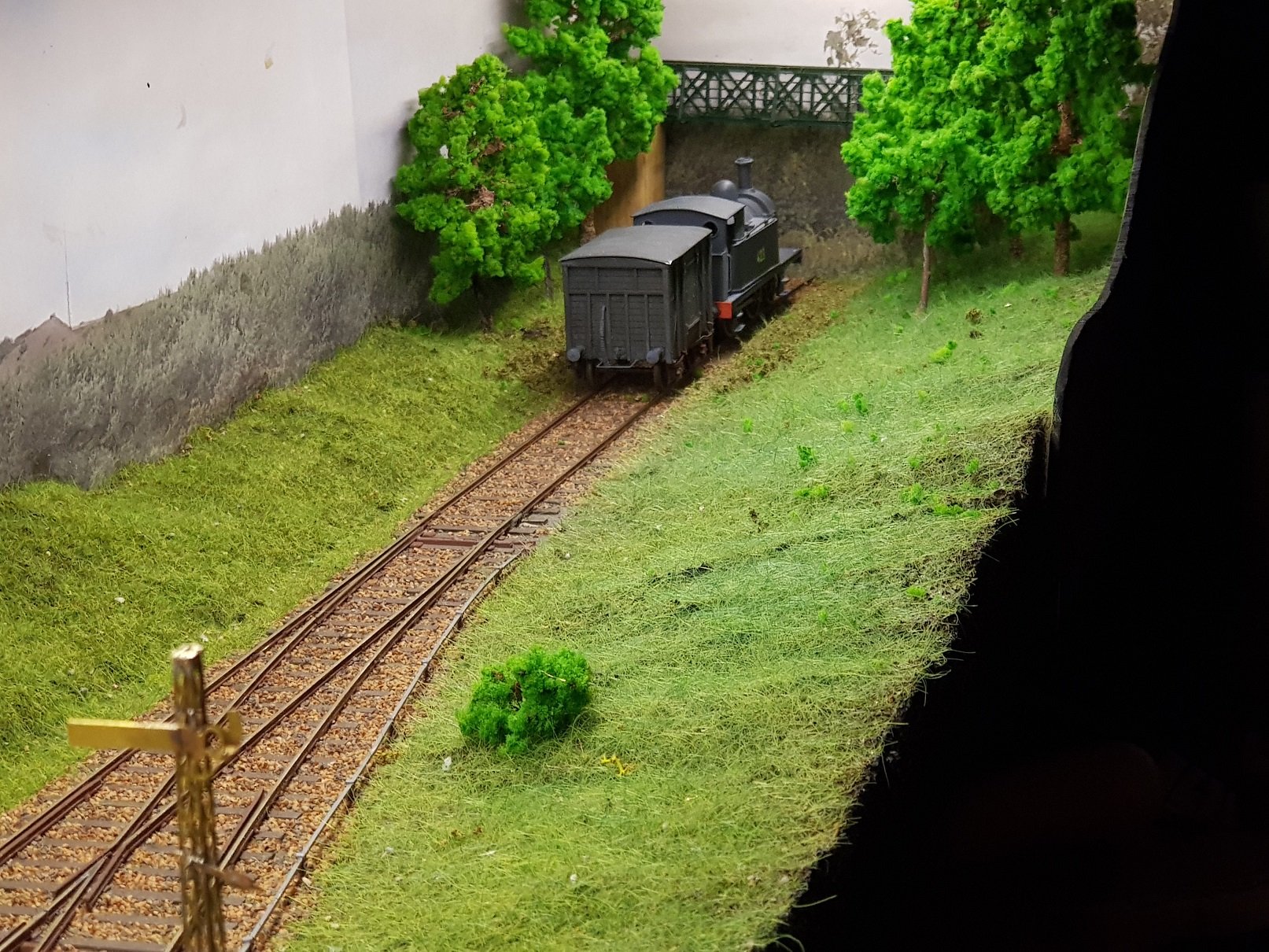
Time for a new layout, or re-hash of an older layout. Some time ago I developed a small shunting layout which developed into Wicklow South, however given the lack of goods movements in the passenger station, there was not really much potential in the layout. Wicklow was one of the few towns on the DSER that had two stations, the original Murrough Station, and the later through station for passenger use. The original layout was documented here: But for the sake of convenience the original shelf layout: The backstory for this layout is a small fictitious station on the Shillelagh branch line between Woodenbridge and Aughrim. There is a nice road bridge over the railway line with a flat area back from the river in a location originally called Coat's Bridge; this townsland is on the older maps, but does not show up on newer maps. So in this story line, a small station with a goods siding was built to serve the small community, all in the typical DSER style. The roadbridge allows for a nice scenic break to cover the hole in the sky to the............ traverser, maybe, but possibly cassettes as the layout will continue as a shunting layout, but in a more cameo style. The original layout was integrated into a larger baseboard which allowed for a small increase in track length. The short siding in the old layout was lifted and a longer goods siding was added. A partial relief goods shed will tuck in the corner with an extended goods platform which will include a yard crane and small cattle pen(s). The idea being that the landscape will creep right up to the cattle pens to plant it into the layout. Up and down partial platforms with a typical DSER signal cabin and footbridge will close out the end. The unfinished box and the end of the platform will be a water tank, the idea being that the signal cabin and water tank will help form a scenic break to hide the track ends. The complete layout will be encased with sides, rear and proscenium arch at front to frame the complete layout - that will follow as it is easier to work on the layout while it is open. Anyway, early start (re-start) with much to do, and hopefully will prove to be a good up-cycling of an older layout. All for now, Ken
- 22 replies
-
- 18
-
-
-
Seriously impressive model - does anyone know where this is now - does it still exist?
-
......Cheers, much appreciated. A little difficult to determine as there are so few photos of DSER stock, and even less of DWWR. Having said that, there are some good photos on your Mount Bellew page 5, one of which shows an early DSER cattle wagon based on the covered wagon and it appears the lettering to be 2 planks high. I think it would be reasonable to assume a similar size for the convertible which should just fit between the uprights. Their lettering was quite large, so I would err on the larger size - ref page 104 Shepherd & Beesley for an image of the "Hurst Nelson" open wagon in DWWR livery. Hope that helps
- 11 replies
-
- 2
-

-

-
- 4mm scale
- 21mm gauge
- (and 2 more)
-
Many thanks for the comments, and even I have to admit the wagons look good - well done Mark. They do seem to improve with a coat of paint - somehow it helps to highlight the details. With regard to the buffers, those short buffers you have would work well on the convertible and open wagons as they would have had shorter buffers due to the dumb buffer look to the headstocks - I use the shorter buffer for these, with the longer buffer for the cattle and Ashbury. As to livery, I recall you mentioning your era was around 1900 to 1915? - if so, slate grey with lettering in white and plenty of weathering. Hope that helps. Ken
- 11 replies
-
- 9
-
-
-
- 4mm scale
- 21mm gauge
- (and 2 more)
-
Agreed, however you do need to consider the speed of the motor also. High Level does provide a speed calculator on the Help tab. I can't link to it here as when you click on the link it downloads a spreadsheet. This is a very useful resource as it will help you with gearbox selection - for example a motor speed of 15000 RPM with 108 ratio gearbox will give a very similar speed to a 10000 RPM motor with an 80 ratio gearbox. This is particularly relevant for me at the moment as I am trying to change away from 12V motors to 3.7V motors to suit the LiPo batteries & there is a bewildering array of motors from 8000 RPM to 50000 RPM to be had. So this calculator has been essential to getting correct speeds to match the gearboxes I already have. Hope that is of assistance. Ken
- 309 replies
-
- 4
-
-
-
-

-
- mgwr
- 21mm gauge
- (and 1 more)
-
Excellent. Both have merits and depending on your preferences, either way, you will find great advice. I had a great fear of building locomotives and was following the route of bashing RTR locos to mimic Irish locos, but was never really happy with the results. Having read the book (many times BTW), I decided I had nothing to lose and started into scratch building. What I learned is that despite how complex these locos look (including mine) they are built up of small parts, each being quite straightforward to build. No loco just appears on your workbench fully finished, but does come together as each part is built - a very satisfying process. You don't need many tools, however there are some essentials that help in delivering good looking results (thinking of the rivet tool here). Materials are not overly expensive so you can afford to make mistakes & try again. I will warn you though, once you go down this route, Pandora's box is opened and anything is possible!!! Ken
- 309 replies
-
- 5
-
-
-
-
- mgwr
- 21mm gauge
- (and 1 more)
-
Whereas, I went for the second one as I have a soft spot for tank locomotives. My post on 458 class build was based on Boltons second book with strong influence from Flexichas by Sharman. Depends if you want tank or tender locomotives, but as @Galteemore noted, both are excellent. Ken
- 309 replies
-
- 2
-
-
-
- mgwr
- 21mm gauge
- (and 1 more)
-
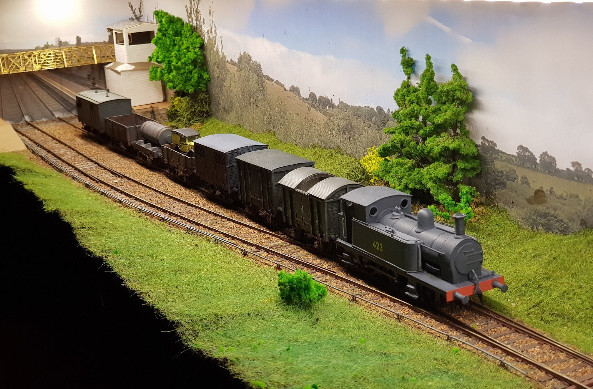
Or change the front axle to a leading axle & convert to 2-4-0T & you could represent a version of DSER 423 Class? Gotta promote the auld DSER - keep my stock valuation up, don't you know!!
- 309 replies
-
- 11
-
-

-
- mgwr
- 21mm gauge
- (and 1 more)
-
I can see many years in the future, some kid in school doing a geography project about the west of Ireland, finding Davids map of how the coast "used" to look, and proceeding to wow the teacher on how climate change has affected the area!!! There will be more kids protesting & going on strike from school...
-
What about a nice DSER Loco? That's around the island too!!
-
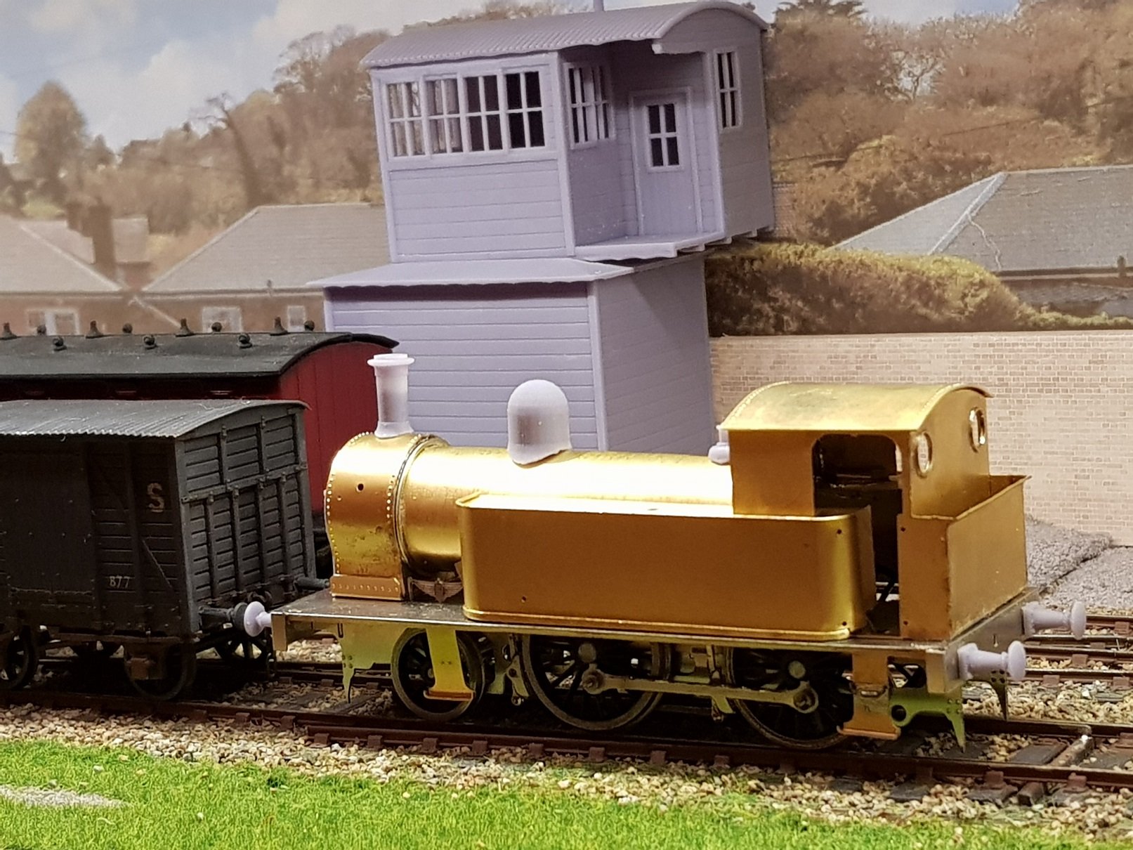
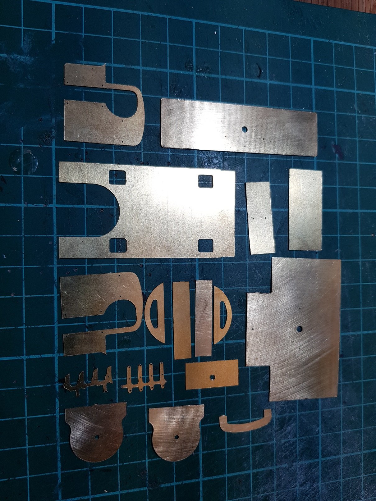
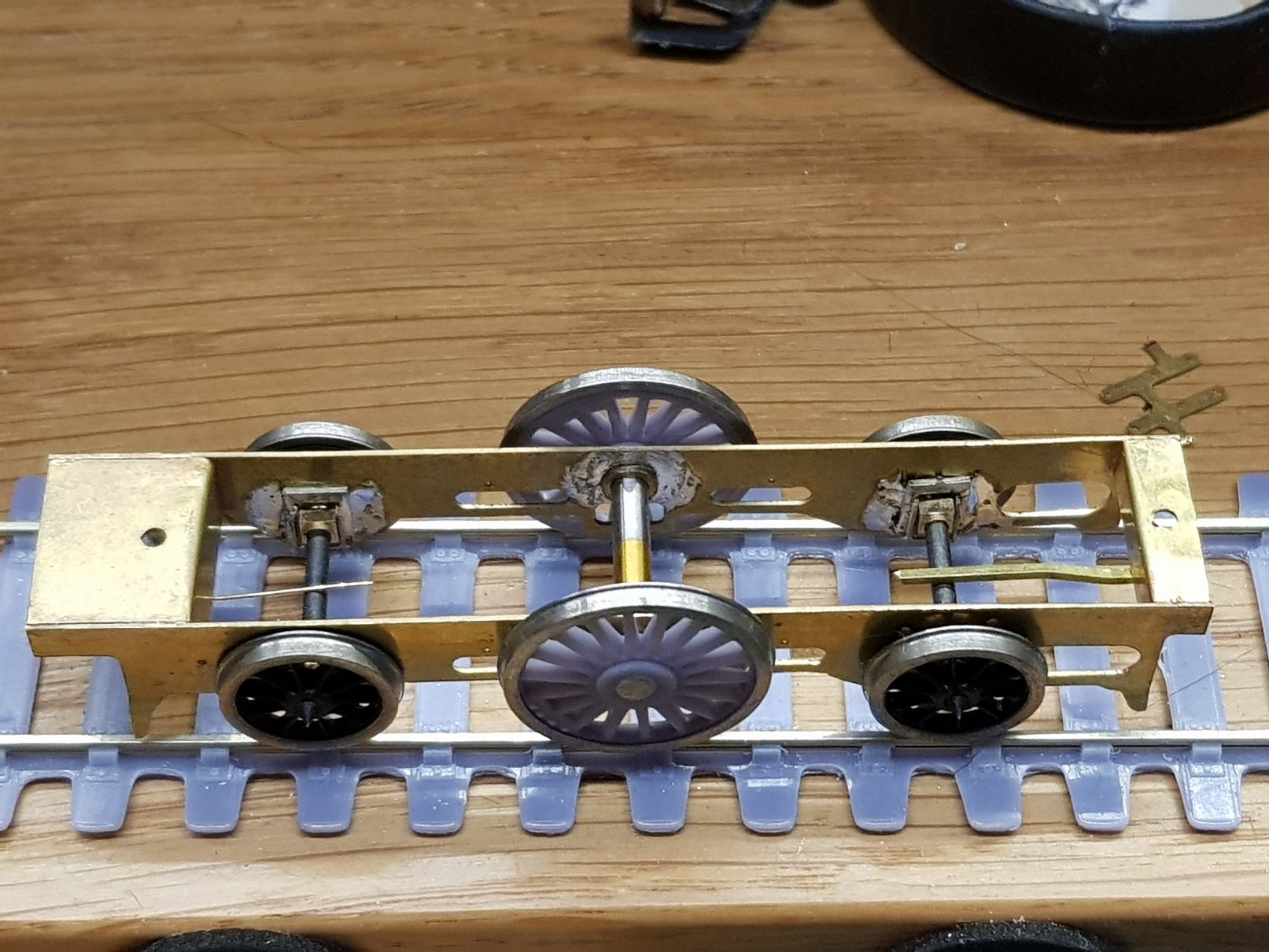
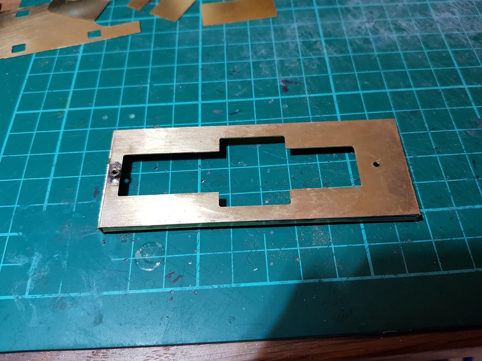
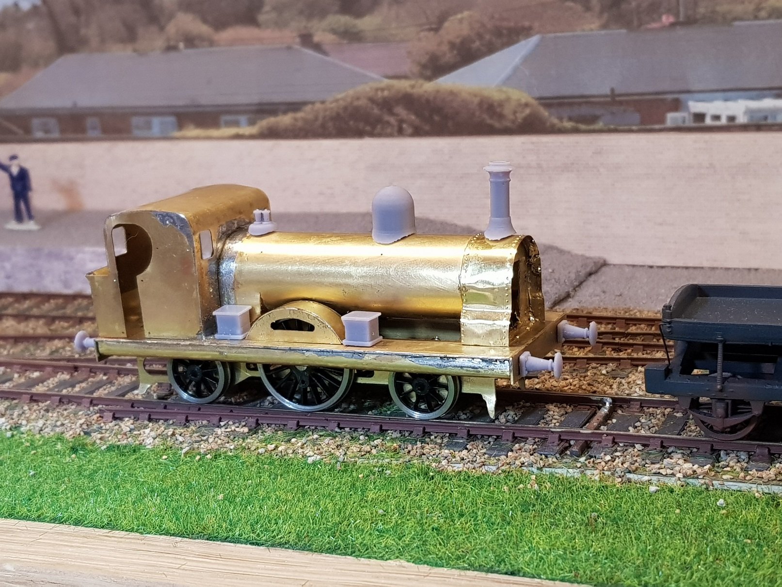
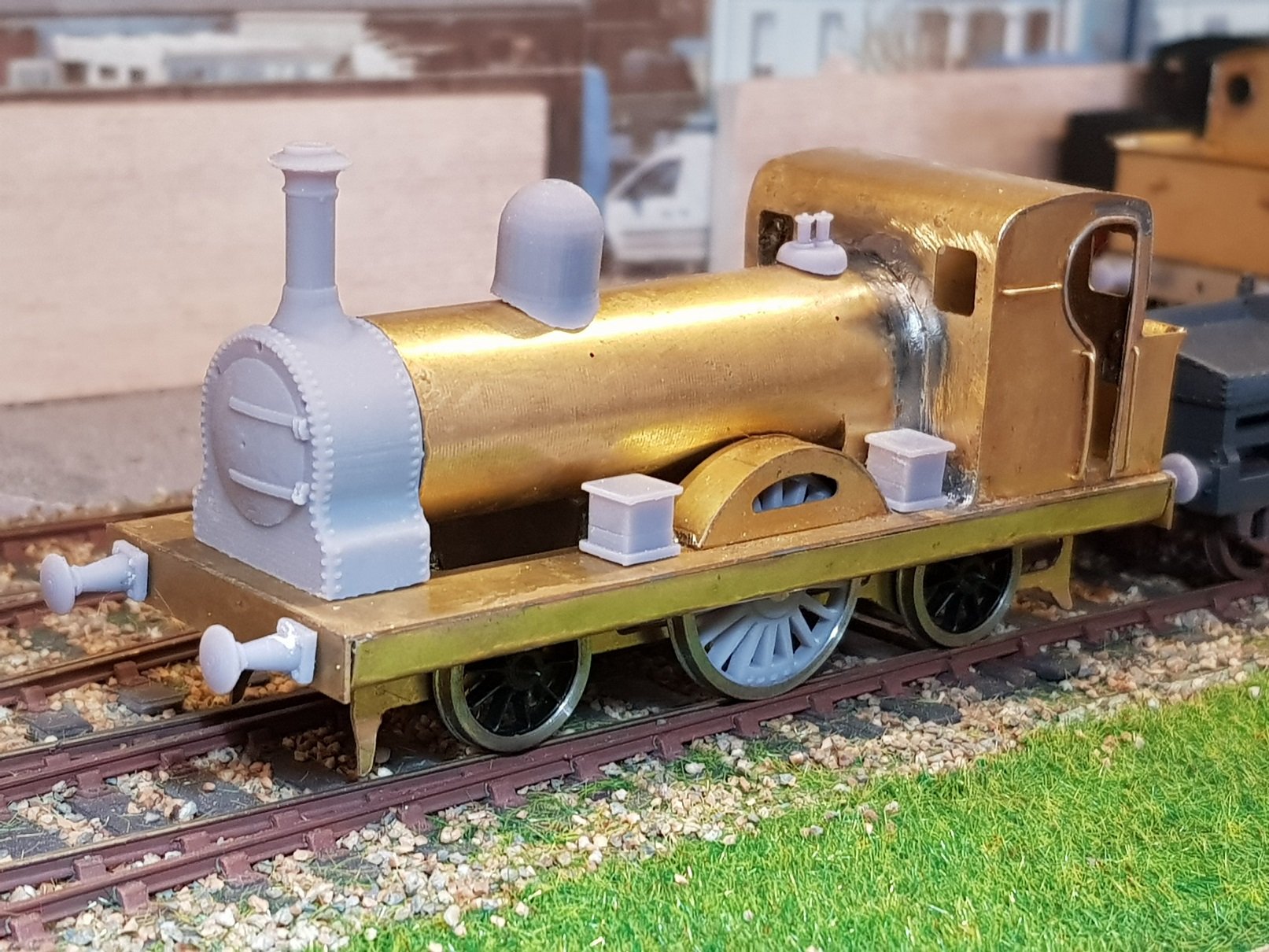
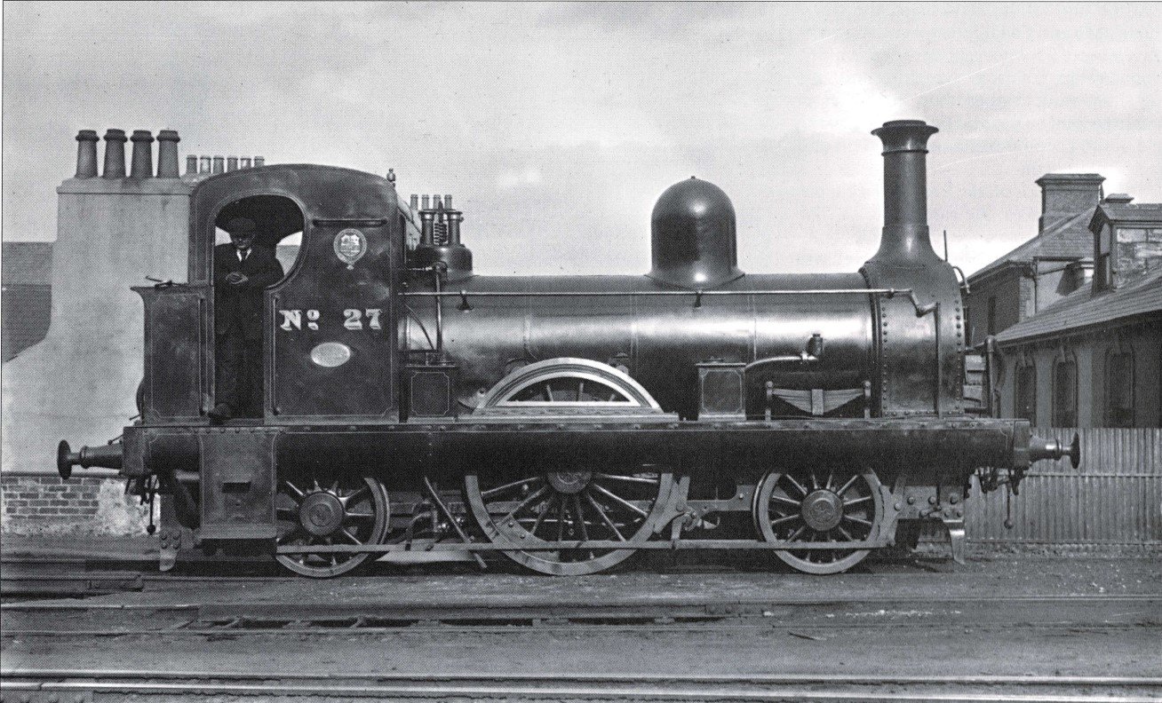
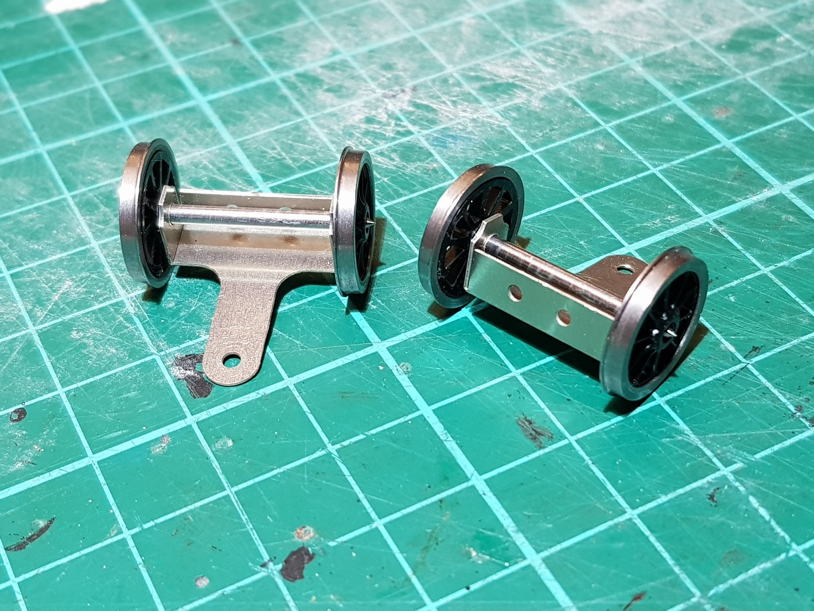
The rake of tipping wagons completed some time ago have been sitting on the test track looking for couplings to be fitted and a suitable locomotive to haul them. Given the last mineral train departed Avoca in 1900, an earlier style of loco will be needed. Thus the excuse to build a 2-2-2WT loco. DWWR / DSER ran quite a few singles, some of them being quite long lived, and most getting a rebuild at some point in their life. The loco I decided to model was the re-built version of Kate Kearney - an ex Dublin & Kingstown Railway Loco built in 1865, which was rebuilt in 1887 and numbered No. 27. Quite a distinctive loco and quite a number of photos survive in both original and re-built condition. Image courtesy of Shepherd & Beesely - Dublin & South Eastern Railway p82. A CAD drawing was developed from the photo & figured dimensions available of the loco & a cut file generated for the CNC mill. I neglected to take a photo of the chassis cut, but this was assembled to provide a nice rolling chassis. Centre driver is fixed with compensation of leading and trailing axles. Trailing axle is limited in vertical travel by means of 1mm brass strip, while the leading axle is allowed to move with springing provided by some phosphor bronze wire. This set-up allows a relatively stable loco which does not pitch around the centre driver. A this stage no gearbox or intermediate chassis spacers have been installed as I am waiting for some 3.7V motors to arrive so I can develop a battery / motor / gearbox arrangement. The footplate is basic with maximum cut out to allow various motor gearbox combinations. The valance under the footplate is interesting and looks like tanks, so 0.1mm brass sheet was used to allow a tight curve to represent this. I remembered to take some photos of the body elements (in 0.35mm brass) prior to assembly! What is missing above is the proposed smokebox wrapper. I decided to use 0.1mm Brass for this as the 0.35mm was too thick to follow the more complex curves of the smokebox formers - I mean, what could possibly go wrong? Similar to the recent locos, I propose to use 3D printed parts for the smokebox front, buffers, chimney, dome, safety valves and sand boxes. So all this came together to form this.... Hmmmm.....that smokebox wrapper didn't quite work out. It did follow the curves, but is very sensitive to heat & didn't quite settle the way I wanted. So - as the plan was to 3D print the smokebox front, why not print the entire smokebox. That's a bit better. Also this gave the opportunity to print the chimney as part of the smokebox avoiding another joint. I had no drivers suitable for single operation, so I took a cranked driver and printed a new spoked centre - advantage being, I can add the counter weight into the print & kill two birds with one stone - so to speak. The curved valance / tank arrangement is a little more visible in this photo as is the limited view through the splasher - I think I will redo this element as the prototype had a more of a view of the spokes. More work to be done, but promising start. This one will probably be finished in DWWR livery (not looking forward to the lining!) which will be more in keeping with the age of the tipping wagons. I will finish some 3-plank & mineral wagons in DWWR livery also to provide some additional running options. More as progress warrants. Ken
- 379 replies
-
- 18
-
-
-
Fantastic work Sir. Looks excellent.
-
You're in good company here - I really struggle with Templot and basically use it to generate templates for points which can then be exported in .dxf format and then imported to CAD. I use the templates with some basic lines representing running lines while trying to establish track plans in CAD. I have given up trying to develop a full track plan in Templot - I think I saw somewhere a comment from the developer that it was not intended for full track plans, but more for difficult elements and templates? As to point nomenclature, basically A to F - short to long, 5 - 12 crossing angles (1:5 to 1:12 sharpest to smoothest), so while an A6 & B6 technically do have the same crossing angles, the run up to the crossing is longer, thus smoother with the B type point. I know from experience that my locos and rolling stock much prefer the longer point! I'm sure there are others on here who can provide a more technical explanation. Hope that helps. Ken
- 309 replies
-
- 2
-
-
-
- mgwr
- 21mm gauge
- (and 1 more)
-
Hello Mark, I am working to P4 standards and am a member of the Scalefour society. As you have seen on another topic, I have been developing 3D printed track and point work, hence why I know the dimensions of A & B type points. Using P4 standards I have found that anything over 4 coupled will require at least A, and preferably B type points to run smoothly. The Port Breige layout uses a Y point to try to reduce space, but that still has an 800mm radius, which is workable for short 4 coupled locos. The recent J26 loco just gets through in one direction, try change to the other & the first axles have a tendency to ride up over the track. Other layouts with longer points are more suited to larger locos & I am developing plans for a larger layout (still portable) with B6 points which I will show here once I have settled on the layout and build. Hope this is of assistance. Ken
-
Second boiler complete. I scratched up a new smokebox sheet as I knew the kit version was too short. I think I will include the second row of rivets towards the bottom of the smokebox as they add good detail and are prototypical. The printed chimney and dome need a little more work - a flare around the base is needed, so back to school on the 3D CAD & creation of complex shapes! In principle the 3D parts are working and are easier to do than white metal, lost wax, or resin casting, so I think it's worthwhile developing the detail. The smokebox fronts have come out very well, and with some added grab rail & hinge bar will finish these nicely - some coordination with the brass will be needed to ensure both fit without the gap. So now back to PPD with the revised version to correct the minor errors & kits will shortly be available. All for now Ken
- 379 replies
-
- 17
-
-
-
If it is of any use, Scalescenes https://scalescenes.com/ are good for both buildings, & in the scratchbuilding section, different types of materials are most useful. I really like this layout - lots of operating potential, and well spread out as per Irish prototype. I note from the title you are considering 21mm track and working with 21mm myself I would consider the space needed for points. A6 point in 21mm gauge is 300mm long, while a B6 is 325mm long, thus a crossover using B6 points will take 650mm. Looks excellent but takes up a lot of space! I don't know the space you have to work with, but hopefully you will have enough to develop this & I look forward to progress. Ken
- 309 replies
-
- 3
-
-
-
- mgwr
- 21mm gauge
- (and 1 more)
-
Super stuff. The roadway down by the cottages really works - what is most impressive is how it works from different directions. Sometimes these backdrops will only work from one direction, but you really seem to be able to bring different dimensions to it. Well done Sir....
-
Oohhh....that looks interesting. I had a look at his website http://bygiles.com/ - seriously impressive, with videos of the operations. His layouts are very realistic & with the addition of operational traffic really brings them to life. I think I may get a copy of that book. Thanks David.
-
Excellent - you make it look effortless. Sadly this is one area I just cannot seem to manage, never mind master, hence why I use printed photos!! As @Northroader noted, this really does lift the layout. Ken
-
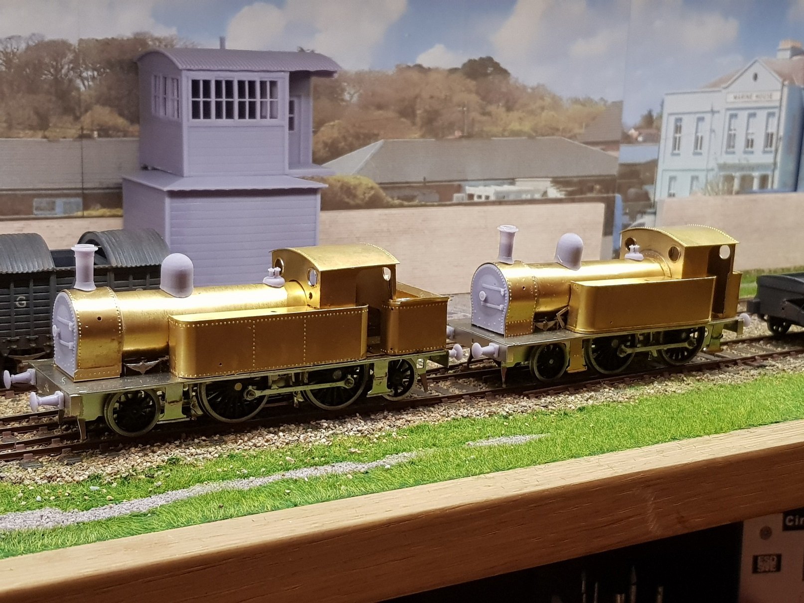
Agreed. The tank top & tank base help to line everything up. Having built two of these now, I'm thinking it may be better to include the tank base on the 0.45mm NS sheet as the brass is a little flimsy. Ken
-
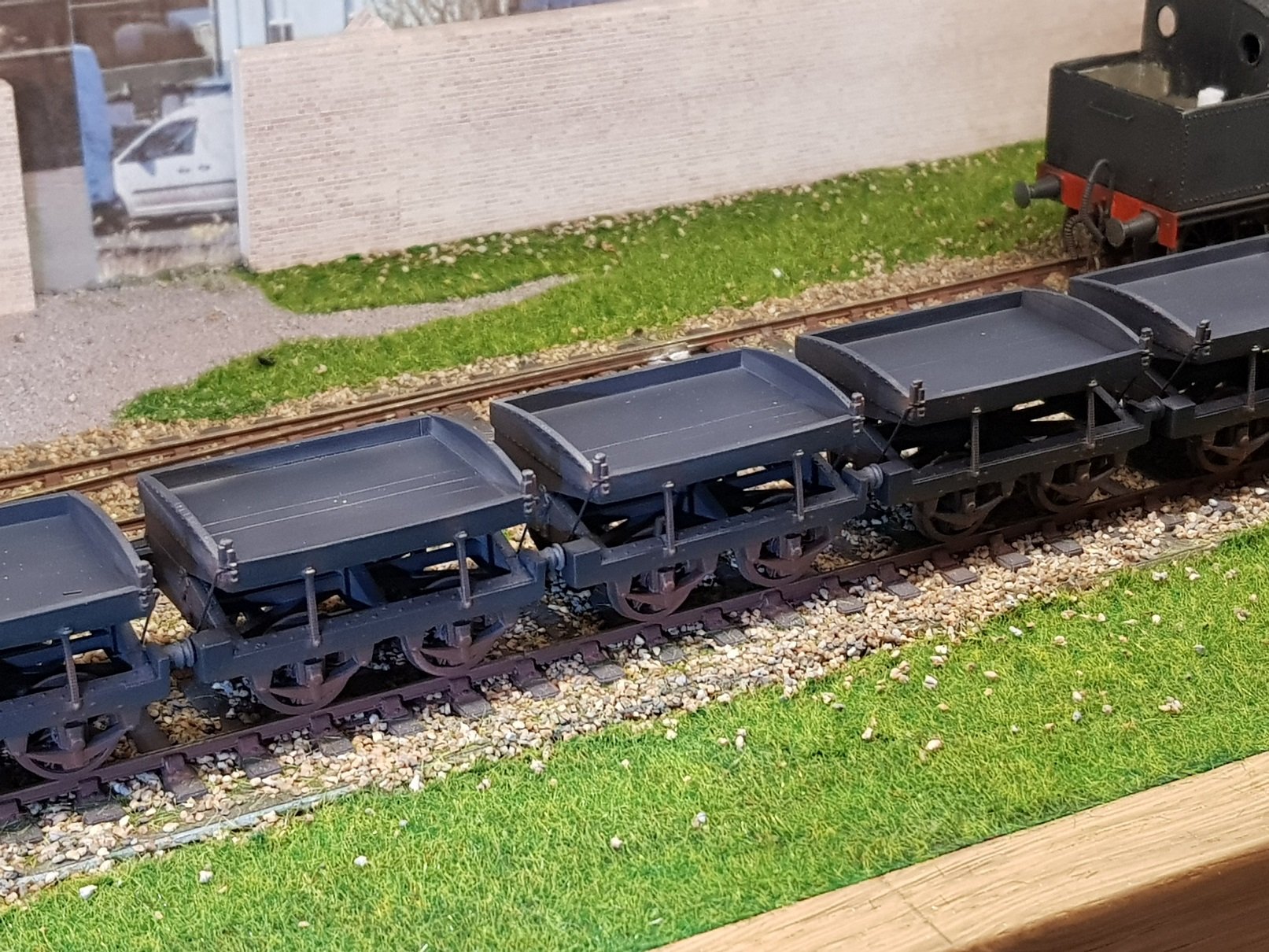
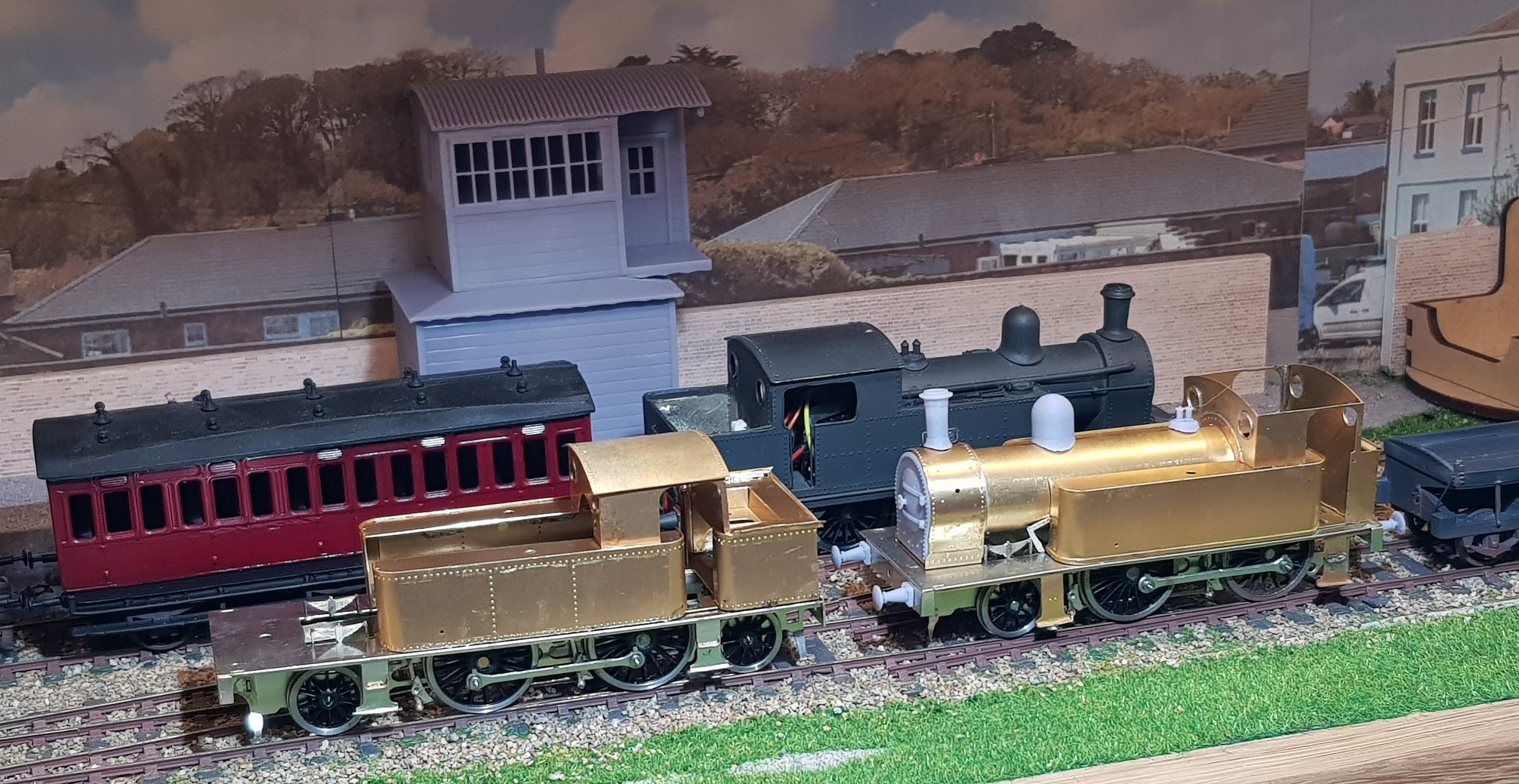
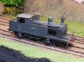
So, over the last day or two the body work has progressed. I should have taken more photos, however methodology used for 423 were followed to build the body for 428. Most of the body work went together fine with the minor exception of the bunker rear not being tall enough - it's about 1 - 1.5mm to low - easily fixed in for the production version. For this model, I'll just add some 1mm strip to fill in the gap. This loco has the connections for the RC switch in the bunker, which will in turn be covered by a faux coal load. Rivets were added while the parts were still in the fret which made life a little easier. Body is not fully fixed down at the rear and the black is basically marker used to prevent solder adhering to the footplate below. Quick photo of the two locos extant. Given the two locos are from the same stable, it is possible to swap boiler - probably similar to the prototype! Quick view as to how the loco will look once completed with the associated 3D printed parts. A few issues to resolve with this kit, the main one being the spacing of the bogie to the leading driver - this is a little more than prototype and needs to be brought back. As mentioned earlier, a tweak to the rear bunker is needed to line things up as well as some minor tweaks common to both models. Otherwise very pleased as to how this loco has developed - nice addition to the stable and hopefully brings another forgotten loco back to public perception. All for now.
- 379 replies
-
- 11
-
-
-
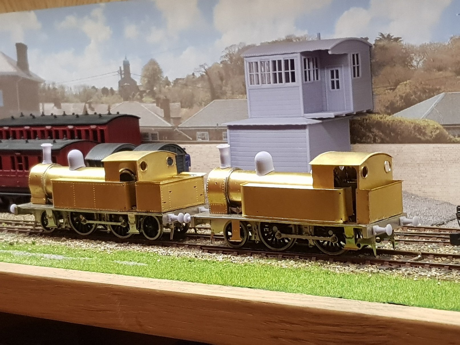
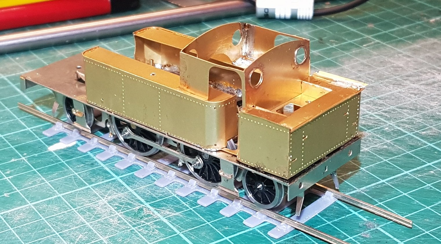
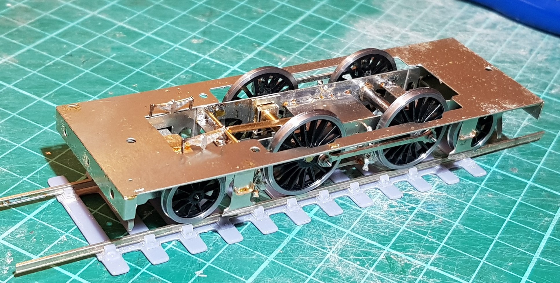
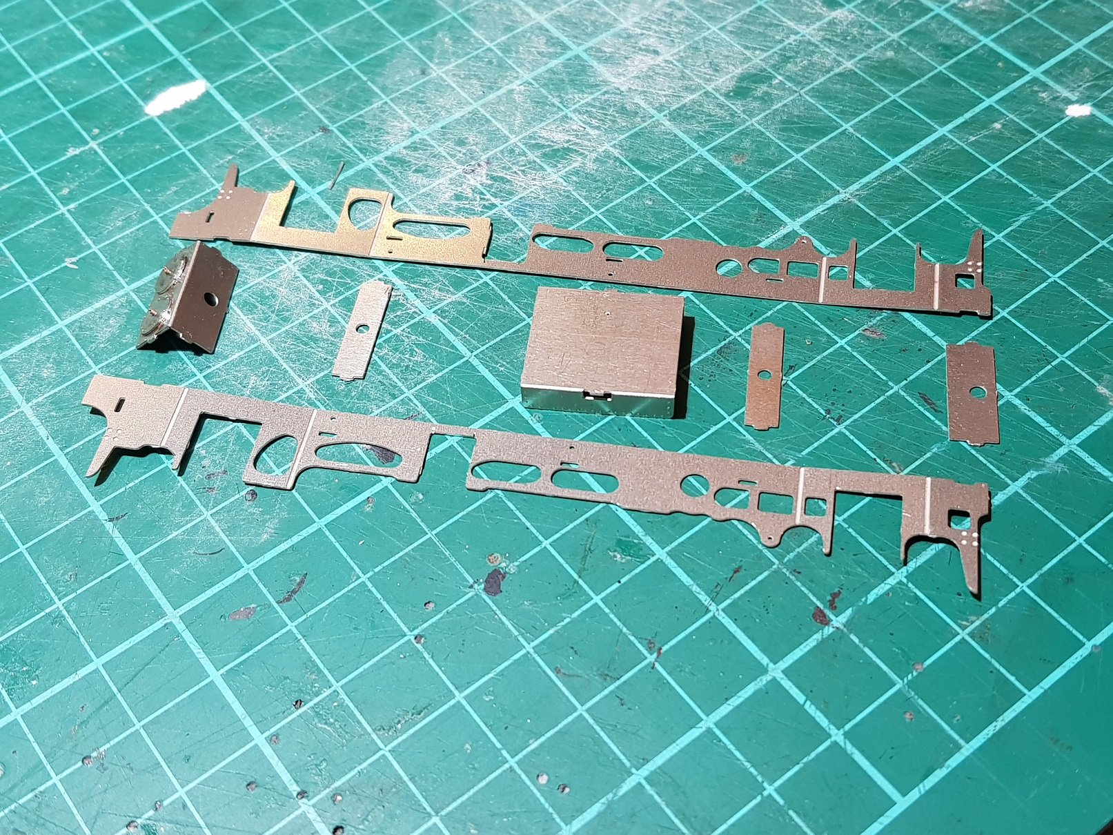
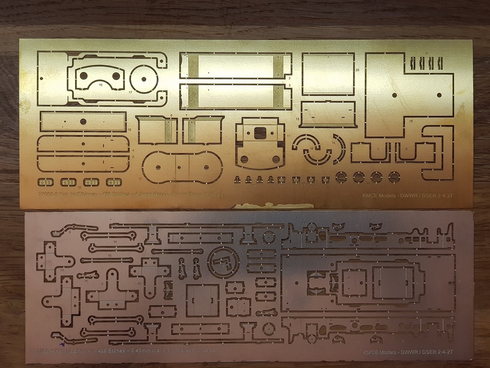
And so for the other kit. In this case a 2-4-2T of the GSR 428 Class ex DSER loco. The 428 Class was a rebuild of the 423 Class shown in the earlier posts. Etches, once again in Brass 0.3mm for the body, and Nickle Silver 0.45mm for the chassis. As this and the previous model are based around the same basic structure, albeit with lengthening the body for a larger bunker & the addition of a trailing bogie, the chassis construction is slightly different. Different width spacers are used and grooves in the frames allow a slight narrowing of the chassis to allow front an rear bogies a little more lateral movement. Faux cylinder fronts were added to the front spacer, and the faux firebox with the fold down sides proved to be slightly over-width, so this was cut at the joint, filed to the correct dimension, installed and sides soldered in afterwards. The difference with this kit is that both front and rear axles are held in bogies which will allow greater articulation of the loco on curves and point work - this, and the cant in the chassis being learned from the armoured train chassis built some time ago. Bogies are simple fold up etches with holes reamed out for axles, which are then connected to associated spacers in the frame using 10BA bolts. The compensation beam included in the kit proved to be too short (doh!) which will be addressed in the production kit, and a piece of T shaped brass with a flat pad used instead. I will need to include a phosphor bronze wire to apply some spring pressure to the rear bogie to ensure it sits properly on the track, particularly in reverse. Brakes added as per the previous kit to get to rolling chassis stage. Footplate was constructed as per previous model, however in this case I included the valances and steps in the Nickle Silver etch which has proved to be more robust than the brass of the previous kit - I'll change the 423 kit to accommodate this. Put it all together...... Body to follow, but all for now. Night, night. Ken
-
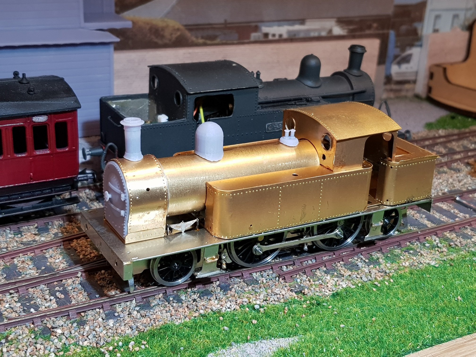
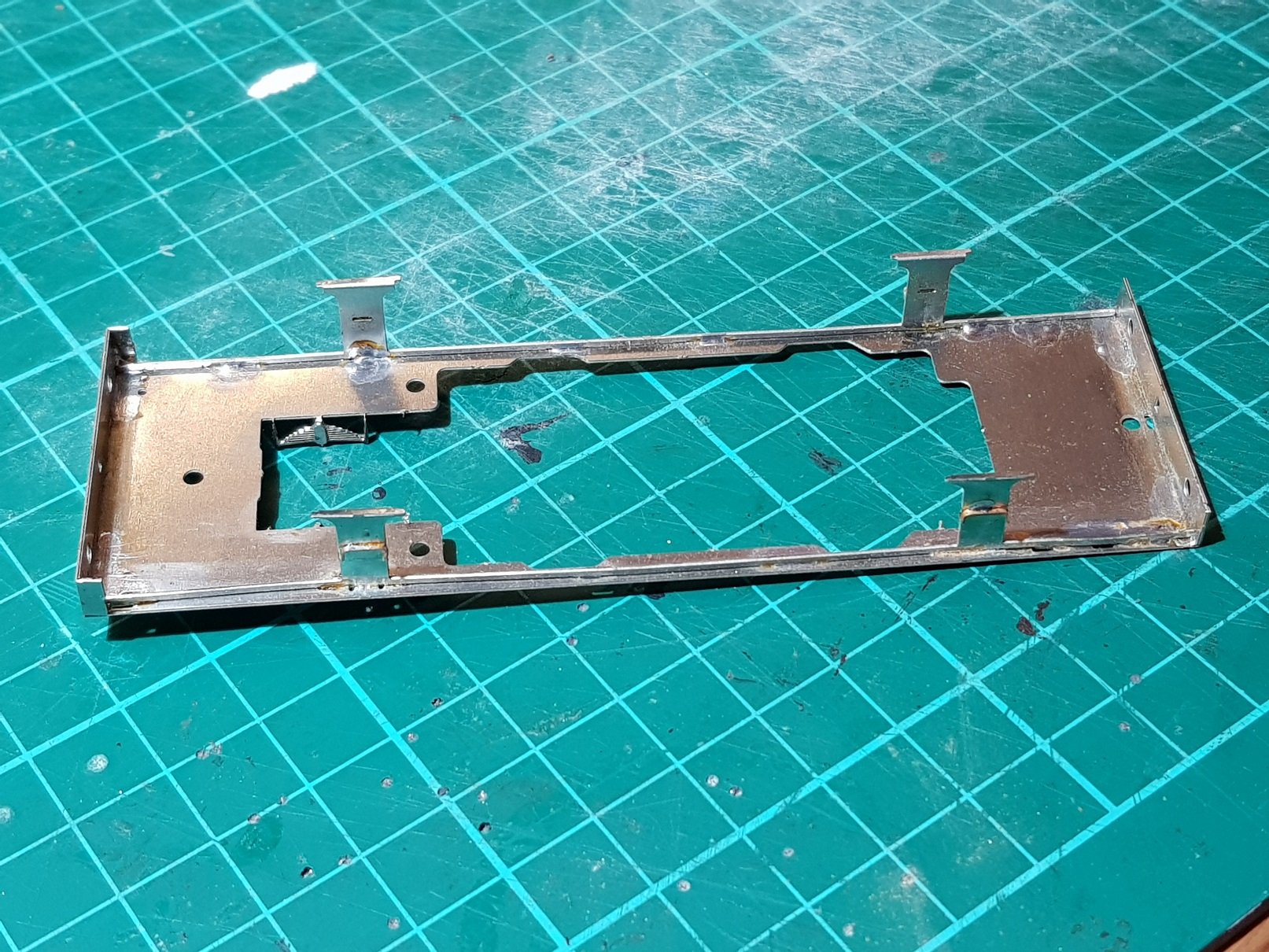
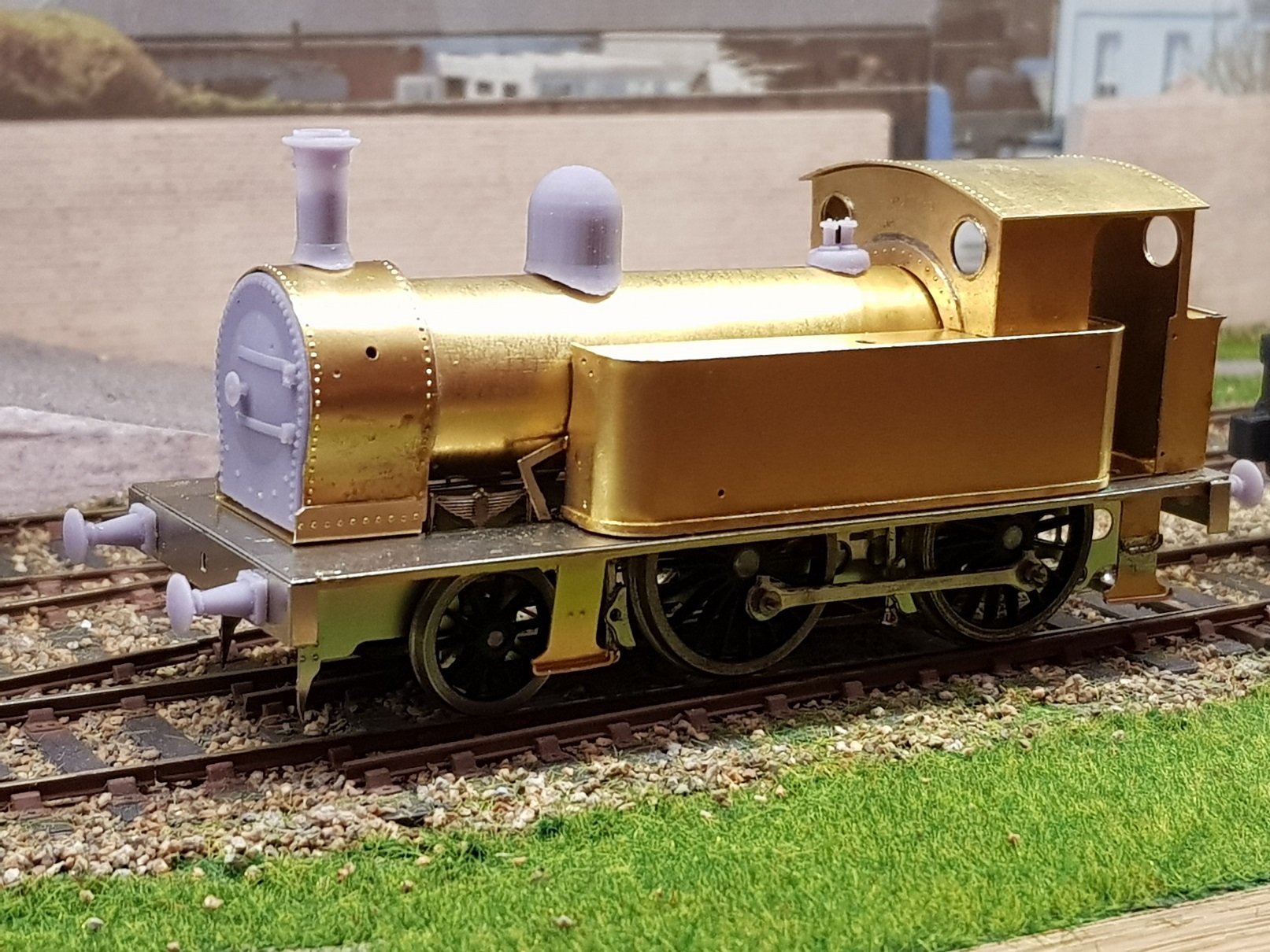
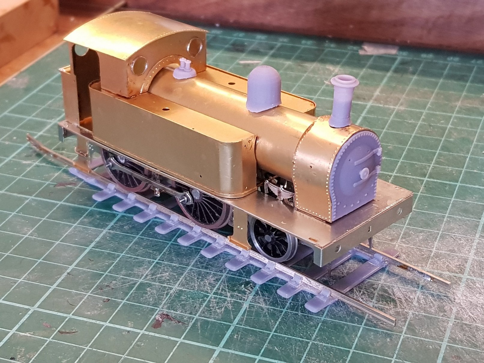
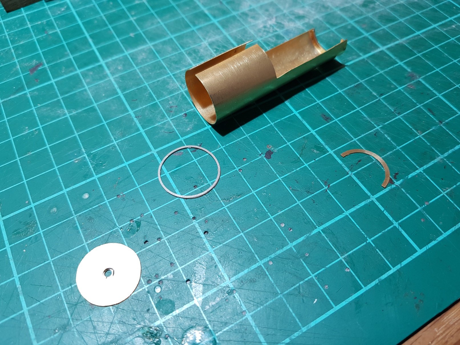
So - boiler & smokebox today. Boiler was rolled & formers used to maintain the shape. The semi circular formers were used where the boiler is cut away, whilst the full circle used to connect the boiler to the smoke box. NS ring is sized to go outside the boiler & provides the stepdown from the smokebox to the boiler. Very useful in getting the boiler shape right also. I didn't take photos of the smoke box assembly, but this consists of soldering in two brass nuts to the smokebox former to hold boiler to smokebox & smokebox to footplate. The wrapper was sweated on. Another minor error developed here - smokebox wrapper is too short, again probably as a result of miscalculation of the metal bend for the smokebox former. The slight increase in height of the tanks pushed the cab up slightly and resulted in a gap between boiler and cab rivet plate. The angle of the boiler to smokebox also needed some adjustment as they were not in correct alignment further compounding the gap. Some judicious filing of the front of the boiler went part way to solving the problem. As the smoke box wrapper did not quite meet the footplate, I created a saddle detail from some spare fret material which helped to cover the gap. Some locos has this saddle detail, whilst others did not, so I can live with this. As noted I propose to provide 3D printed parts for the loco which included smokebox front, chimney, dome, safety valves, buffers & tank fillers. All except the fillers were added to get an idea of how the loco would look. Final details such as handrails, vacuum pipes etc are to be added, but this was far enough to understand what changes will be needed for a future kit version. Armed with that knowledge, I can tweak the etch drawings to resolve these issues. Turning out to be quite a nice little loco. All for now. Ken
- 379 replies
-
- 15
-
-
-
So far so good - some minor tweaks will be required for the release version. Small things like missing holes, or extra holes? A quick check on my drawings & ho-hum, there they are (or not)!!. One element difficult to work out prior to test is how folding will change dimensions. Buffer beams are a fraction oversize and the double fold on the tank base lifted the tanks a fraction up which caused a slight misalignment with the tank former at the rear of the cab. Nothing major, but will be good to get sorted prior to going to press. Generally all going to plan so far.