KMCE
-
Posts
540 -
Joined
-
Last visited
-
Days Won
29
Content Type
Profiles
Forums
Events
Gallery
Blogs
Everything posted by KMCE
-
Yes, i can see where you are going with that one. I have found however, that once painted they disappear into the background. (*Cough*) except where you haven't painted the loop on the loco.... I am with you on the wire across the buffers though - that's a step too far for me!

-
David, If it is of any use, I use Spratt & Winkle couplers on my stock which are relatively unobtrusive and operate well with in-baseboard magnets. They do a 7mm version https://www.englishmodelrailways.shop/media/pdfs/spratandwinkle_O.pdf https://www.wizardmodels.ltd/3_manufacturer/sprat-winkle/page/2/
-
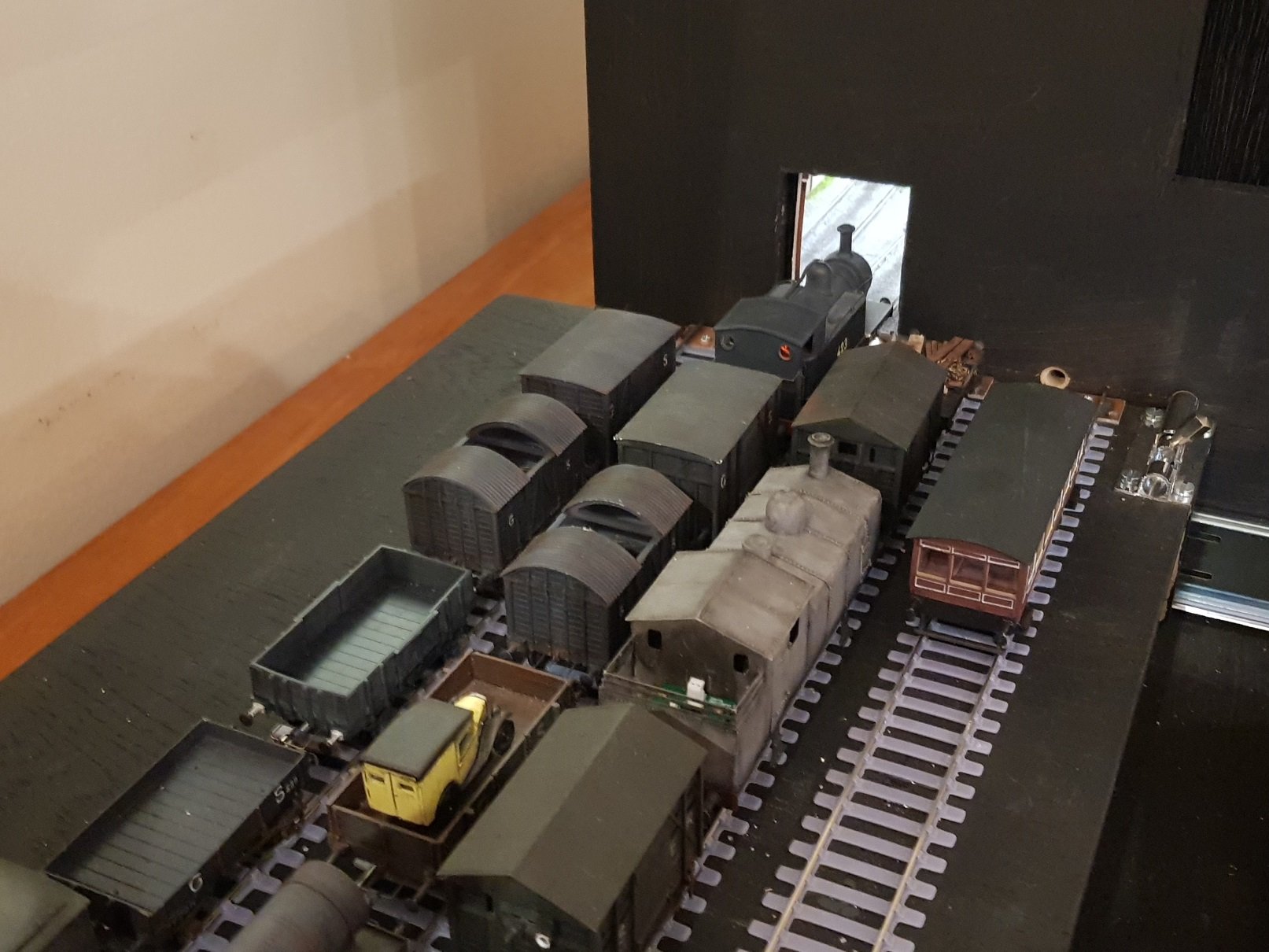
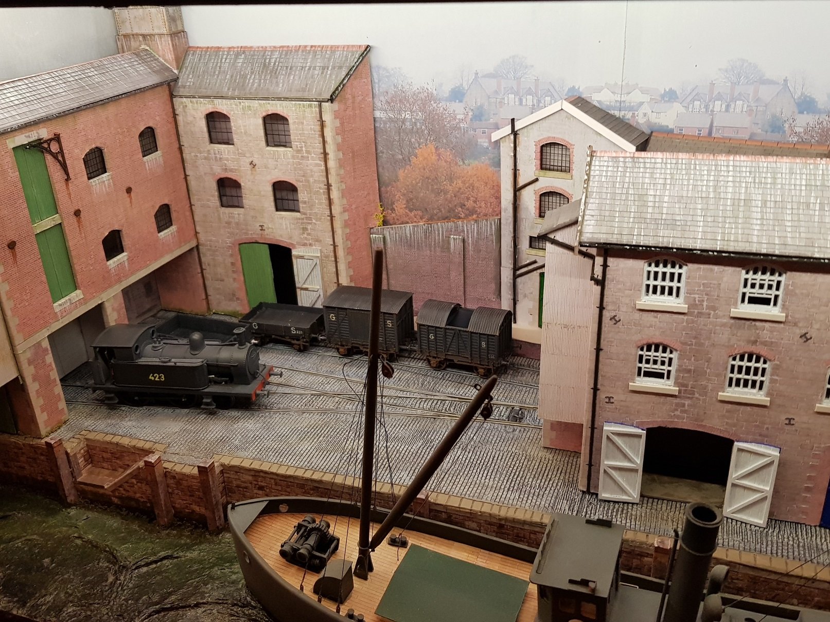
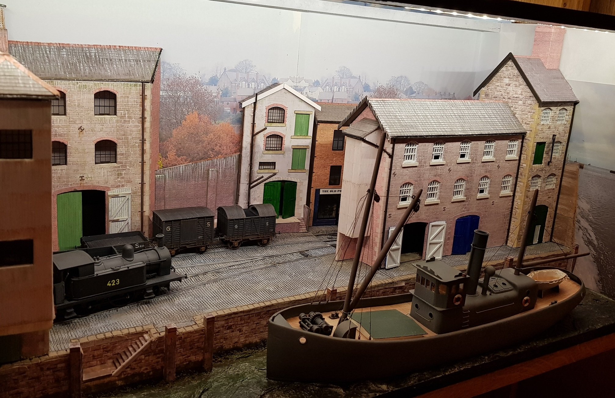
A bit of gardening done which really helps to plant the buildings into the layout In order to improve the operation of the layout, I built a traverser and opened the centre track to allow access onto the stage. Now we have more interesting layout operations with different trains options, however the armoured train is somewhat limited in its movements due to its length, but does give a formidable presence on stage! Anyway, off to the Fair tomorrow in Bray where it can get a proper test drive.....
- 71 replies
-
- 14
-

-

-
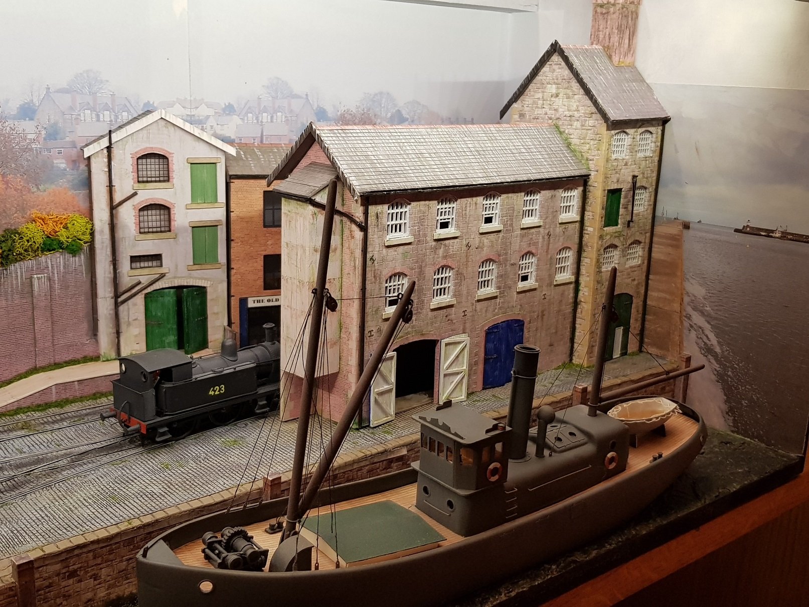
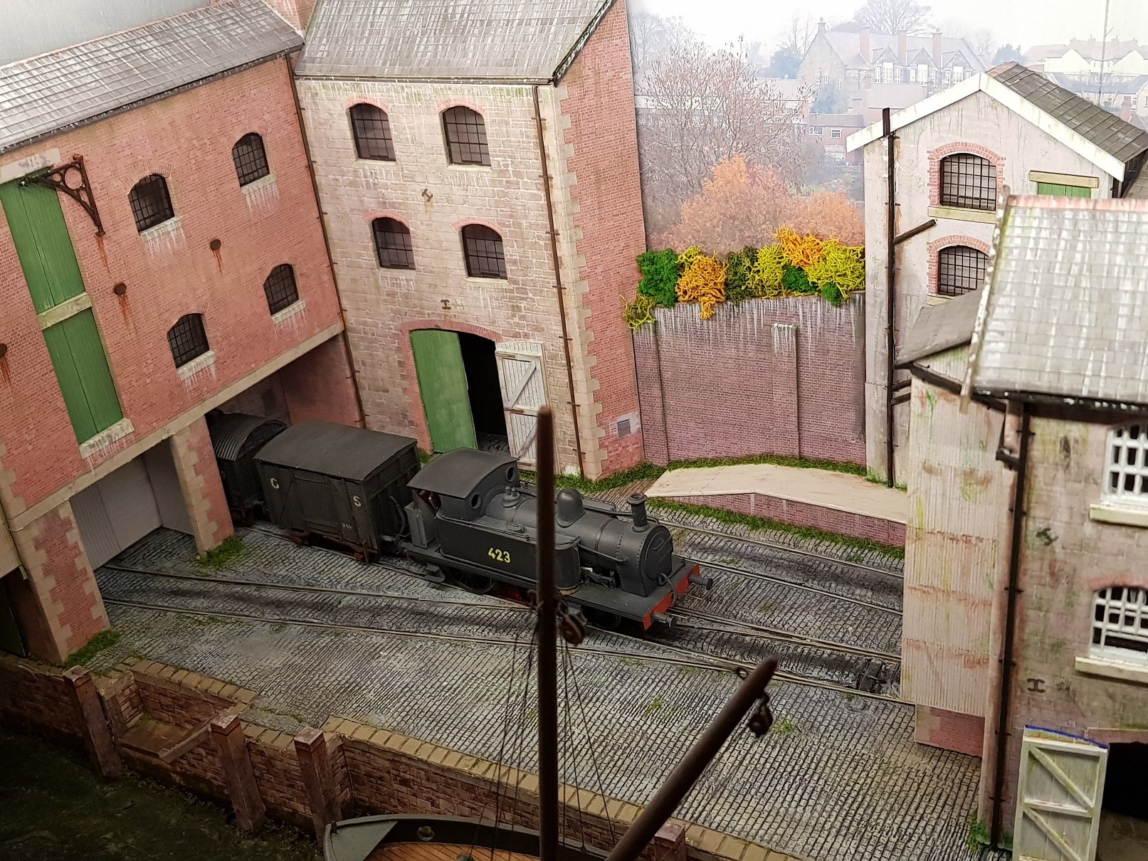
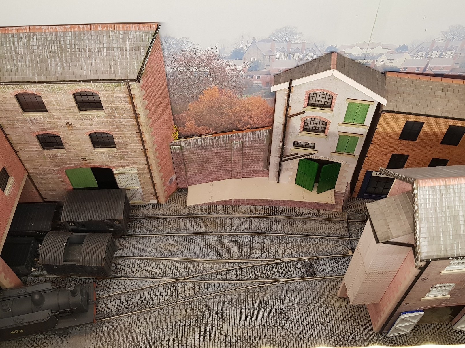
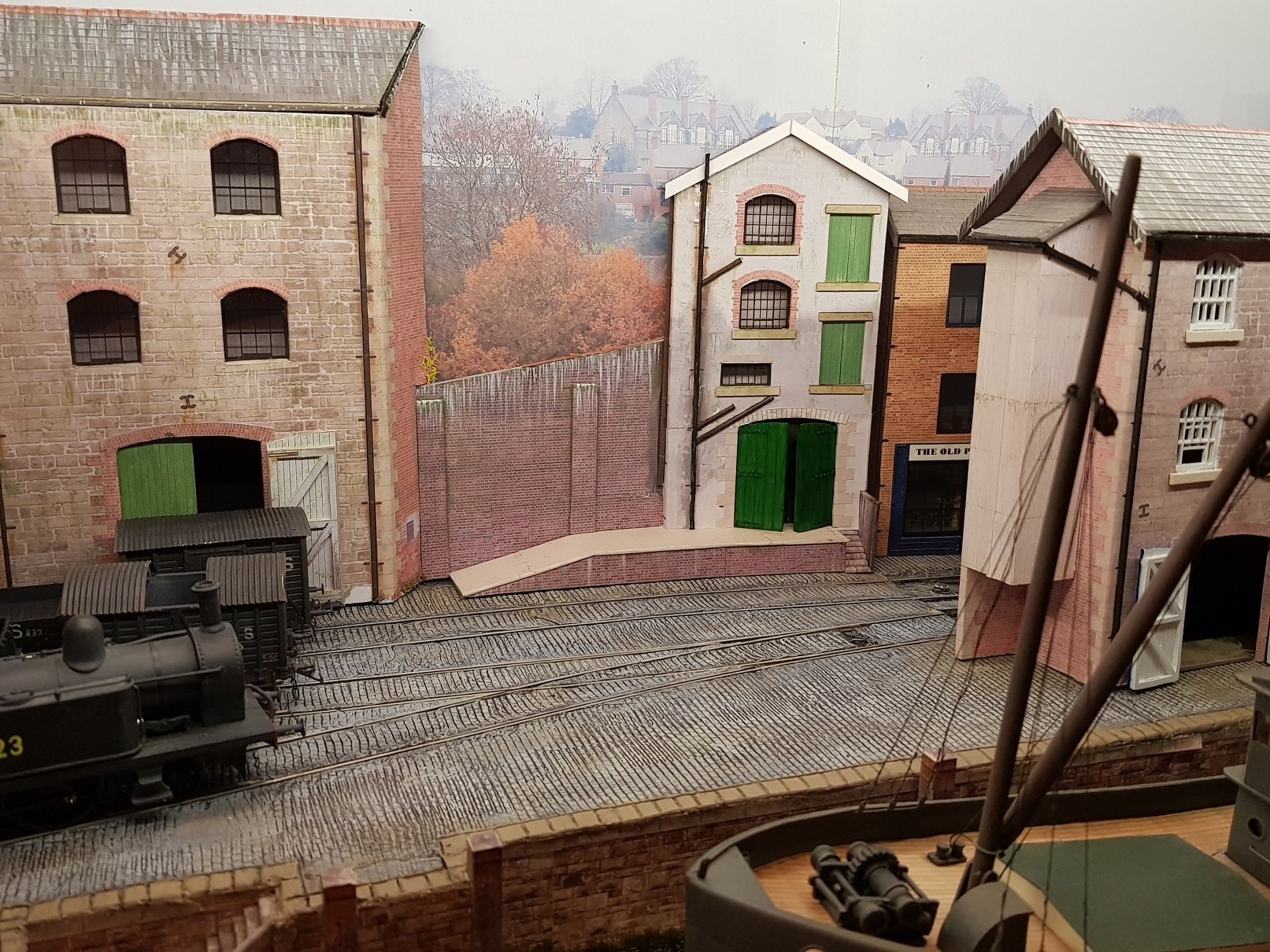
So, the little bit of work to tidy up the layout resulted in stripping back to basic track with all all elements removed. One or two loose solder connections on the track were fixed & some fettling done to ensure locos & wagons went through the points - I was having some problems with the 2-4-0T in reversing through the points, but thankfully solved now. Surface was re-done with DAS clay and a cobble roller I bought through Shapeways. Better looking surface, but the roller was a test of wills & I'm not sure who won!! Painting, black wash followed by dry brushing with light grey, some cream & brown tones to add some variety gives a reasonable result. I still need to do some further weathering with grass & shrubbery to finish the overall effect. I also took the opportunity to adjust the small white building on the back scene to reduce its flat look - Good advice from @David Holman used here with thanks. The angle has really helped to reduce the flat look and the building settles better into the layout. While at it, I removed the stairs, added a platform, and provided some loading doors to repurpose the building. New buildings mentioned in a earlier post were introduced into the scene as a scene blocker. For now all buildings are simply standing in - they need to be fixed in place & some "gardening" done to properly plant them into the overall layout. Still some work to be done but overall an improvement over the previous version. All for now.......
- 71 replies
-
- 15
-
-
This is the one I use and have to say it is an excellent bit of kit. The ability to have different temperature settings as pre-sets is rather good. Reasonably priced, & they have plenty of other solder sundries as well. https://www.circuitspecialists.eu/csi-premier75w-digital-temperature-controlled-solder-station-with-75w-soldering-iron
-
Timely. Just spent the afternoon fettling the track on the Port Briege layout. When I lifted buildings & ground cover there were a few loose solder joints, so tidied them up and spent some time tweaking. Can move on to replacing the ground cover now. It is a tedious process, but nice when done a stock is running through smoothly. Looking good.
-
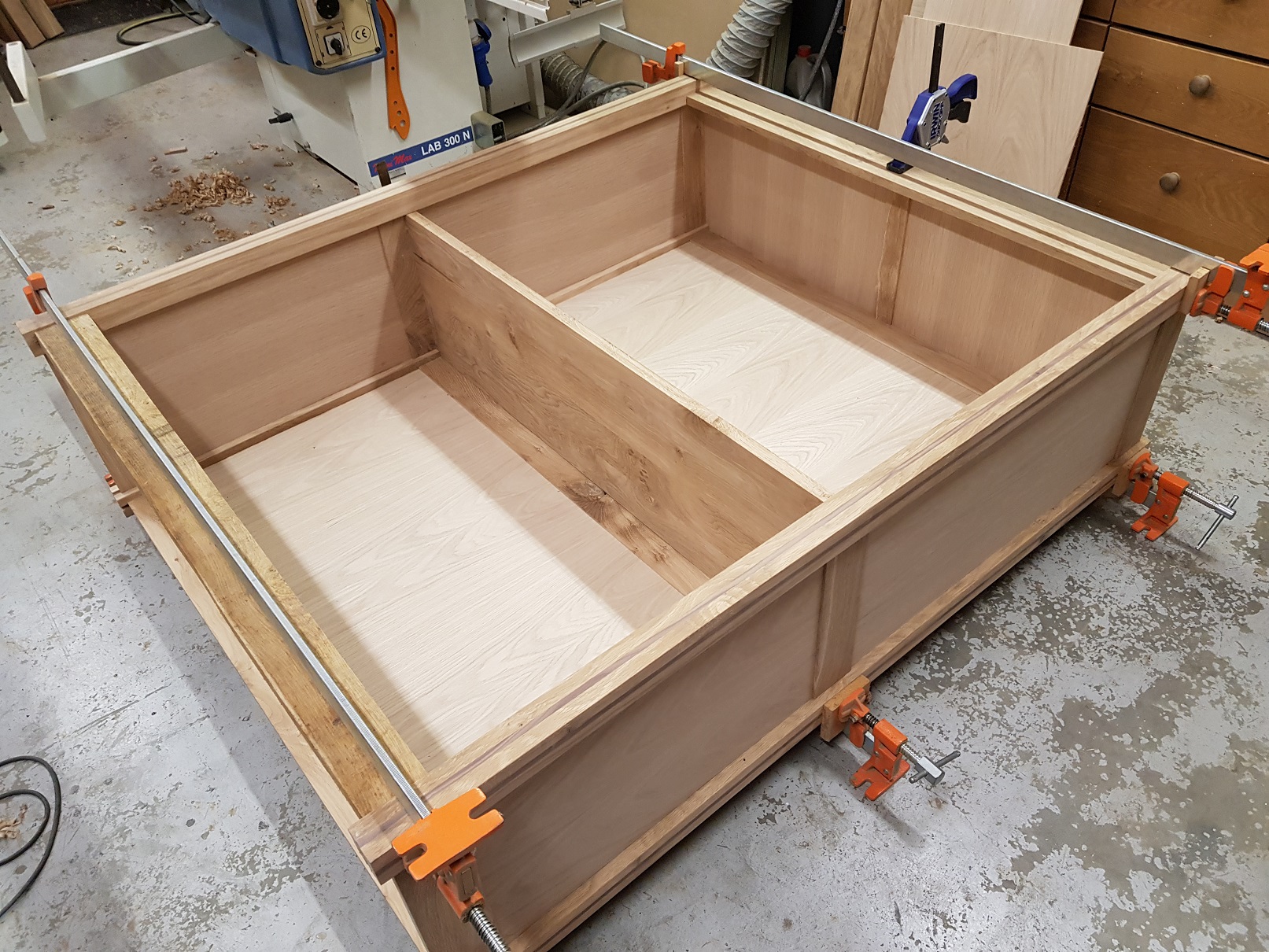
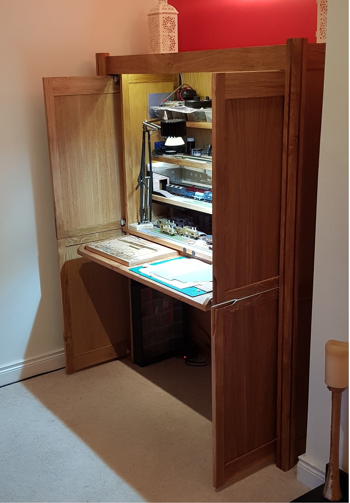
A few more like that & you will not have to build baseboards! You've given me an idea, as I have some unused office desks & cabinets.......
-
It would be hard to see the economics of running a rail line to Glendalough, particularly in DWWR times. Whilst there may be some argument for tourism, the low population & lack of industry would make this route quite uneconomic. Knowing the landscape around Wicklow, any line up to Glendalough would have been difficult. Glendalough is 2,300ft above sea level, and it's hard to see a route through the hills and valleys without recourse to tunneling & viaducts with its associated costs. DWWR were struggling to get the line through to Shillelagh (210ft ASL) by following the valleys and bringing in as many villages / towns en-route to enhance the economics. A further indicator as to the limited DWWR resources is that the Shillelagh branch was supposed to continue on to meet up with Tullow, however this never came to pass. Notwithstanding the above, that would have been a very scenic route! Ken
-
Looks excellent - like the idea of the Polyurethane & those trestles look good!
-
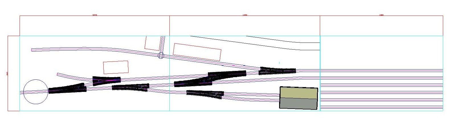
Agreed & I have got to a point where I have a truncated layout in 21mm to fit two boards 1200 x 600 (4' x 2' in old money), with a traverser on the side. Plan was to use the engine shed as a view blocker for the main line and headshunt. Plenty of room up the back for cattle wagons, and it has both a locomotive and wagon turntable (as per prototype), so yes would make for an excellent model. Only 7 points!! Ken
-
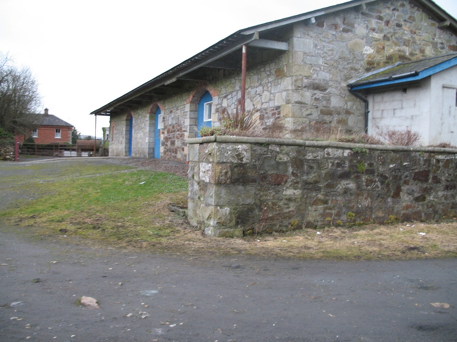
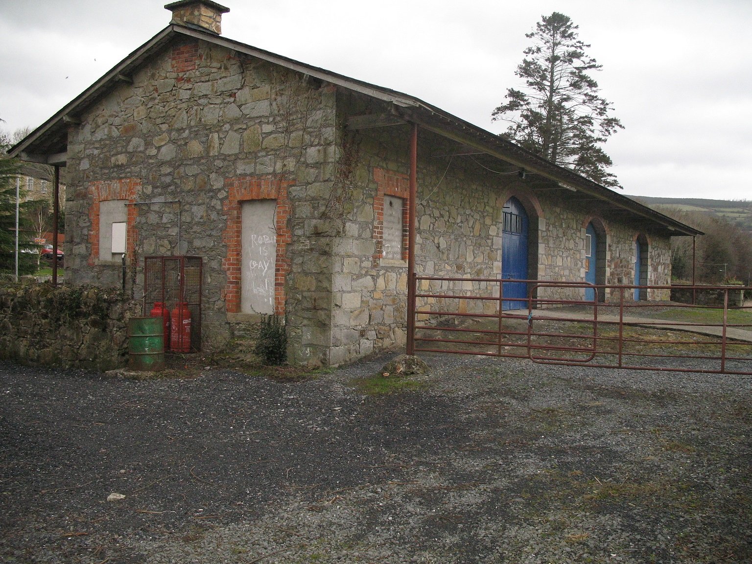
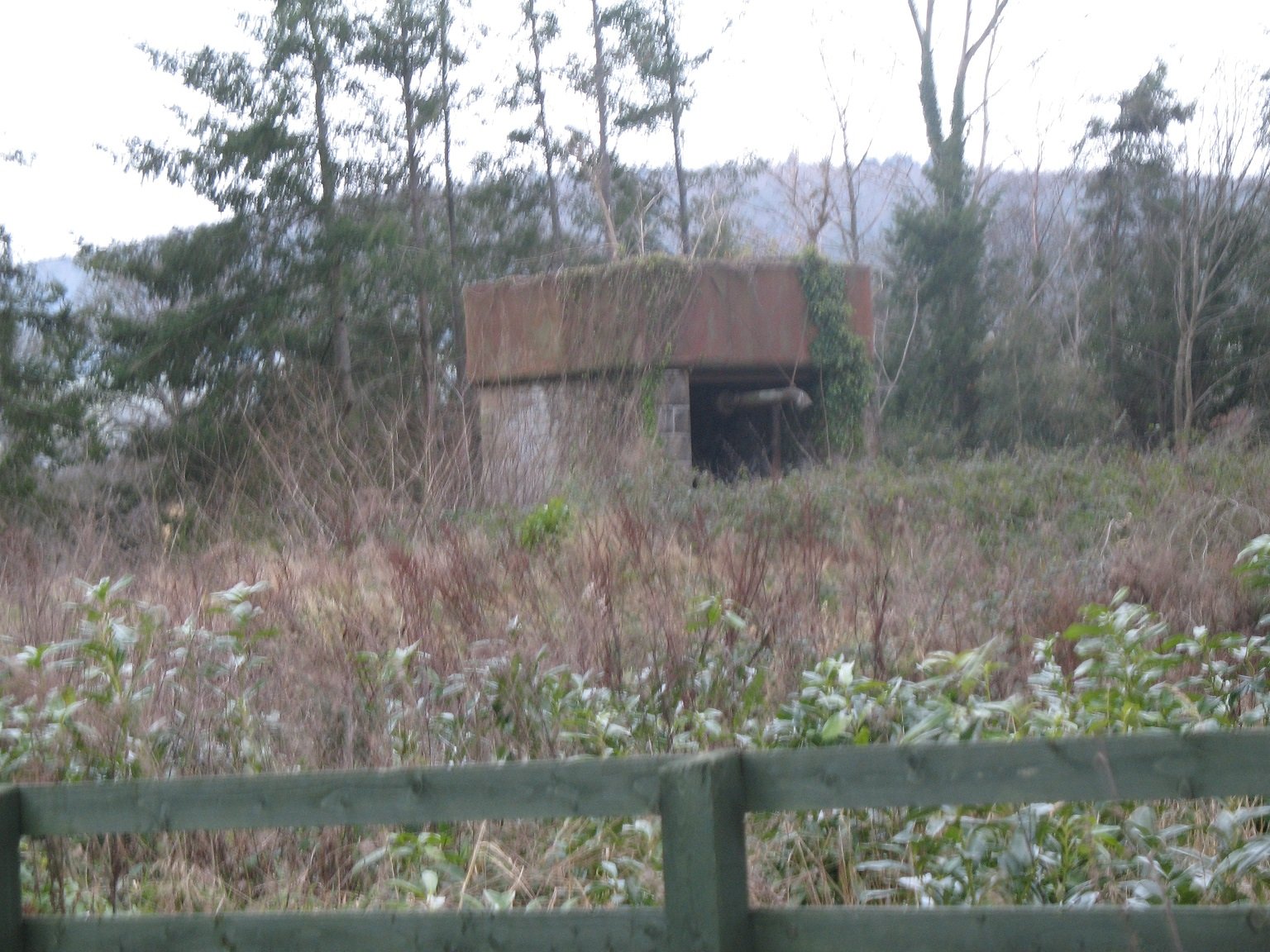
I was up that way maybe 10 years back to get some information with a view to building a model. The station house is still there and in use as a private residence. The goods shed is also still there and was in good condition. Water tank - difficult to get a decent shot as it is further up from the station house towards where the turntable would have been. Still haven't ruled this one out as a layout, but I have a more interesting layout closer to home in the pipeline!! Ken
-
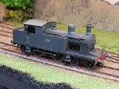
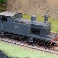
427 was the motive power for the DSER armoured train - not looking so dangerous there though!
-
Excellent photo of Shillelagh, and a rare view looking up the line. Any more of these by any chance?? Ken
-
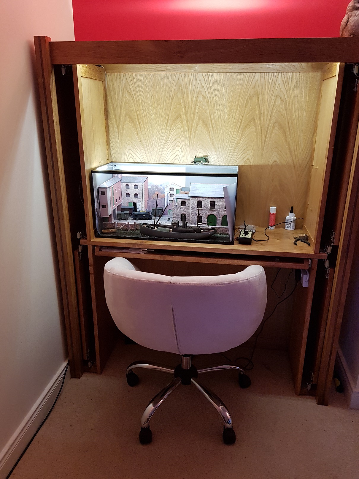
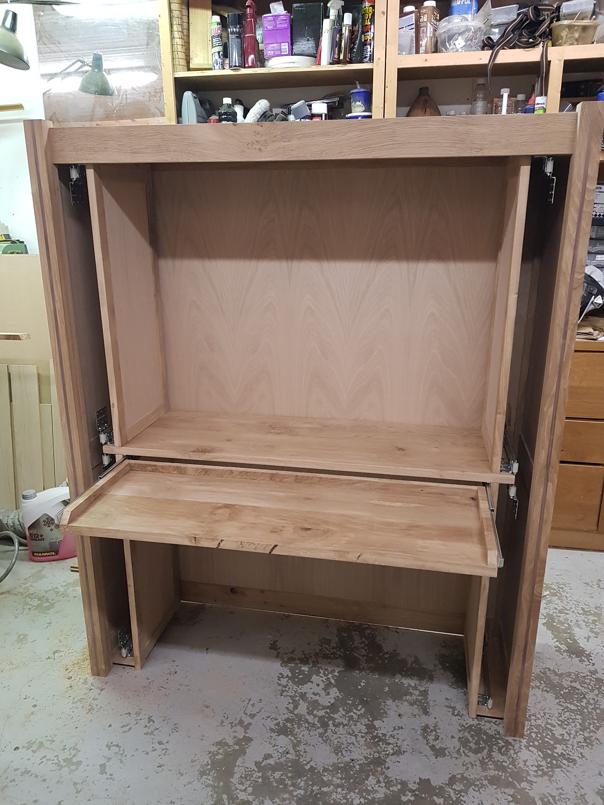
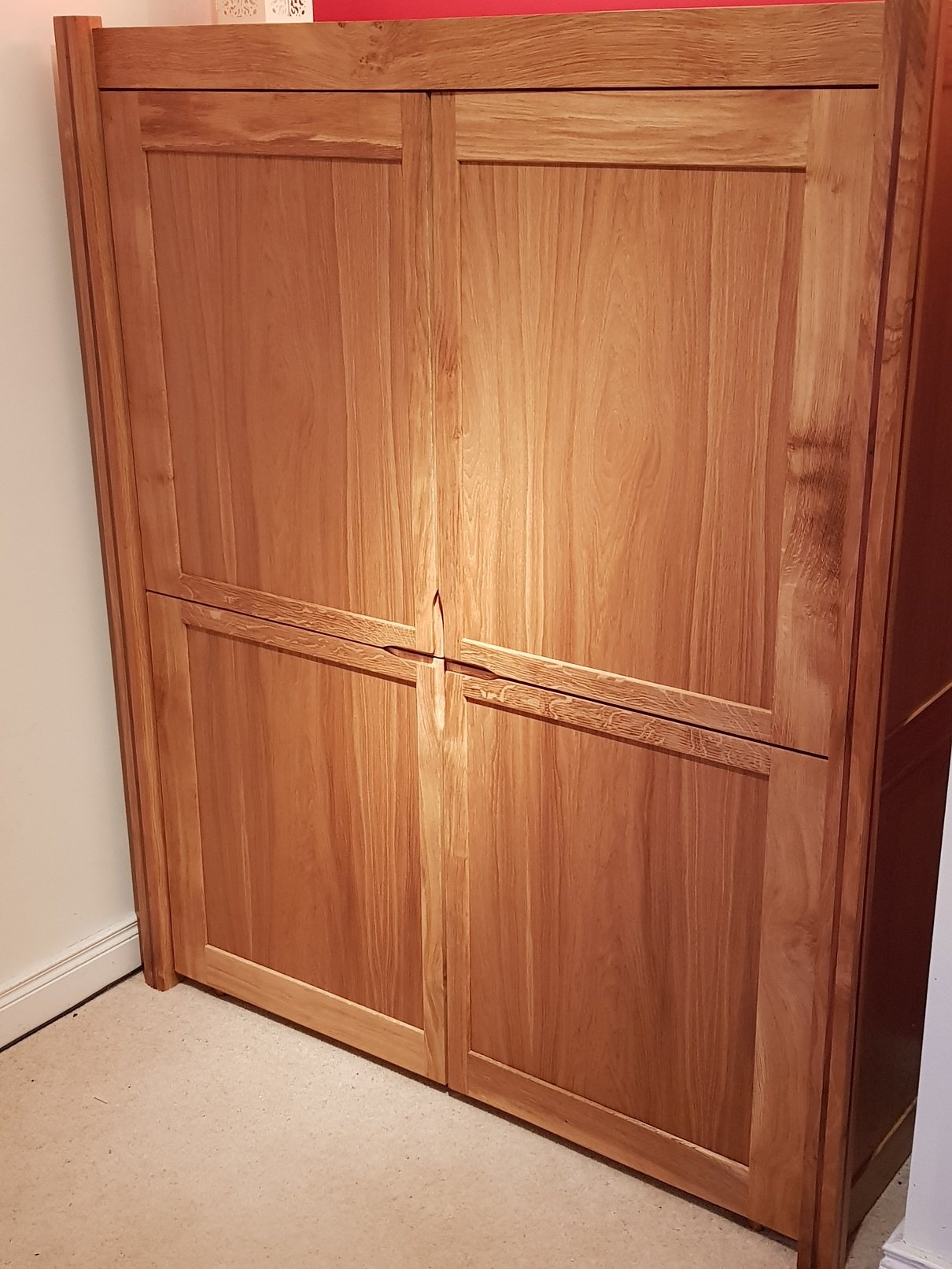
Sooo....it's been a year since I posted on this unit, and only got round to completing the doors over the break. Similar construction to the main unit, and mounted on the pocket door hinges which did take considerable adjustment to get the doors level. Pleased at how it has turned out, and nice to be able to close the unit finally.
- 379 replies
-
- 12
-
-

-
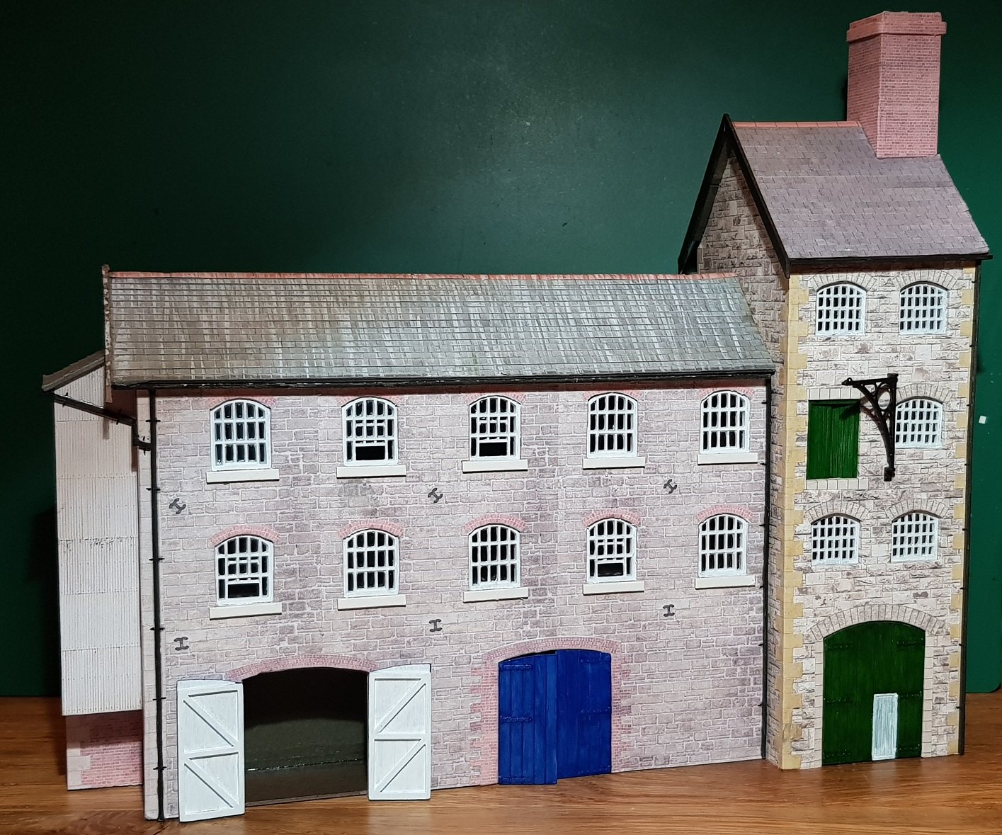
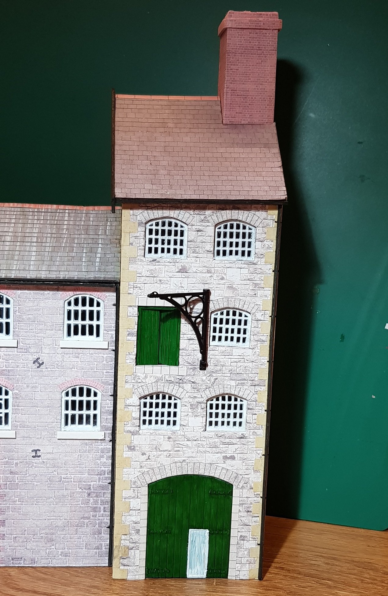
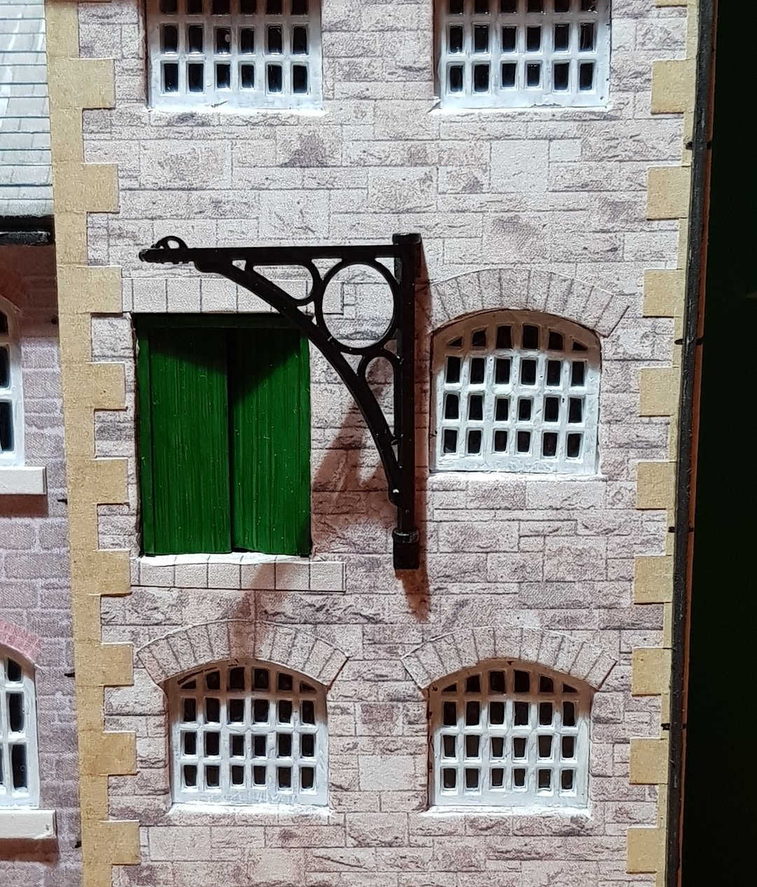
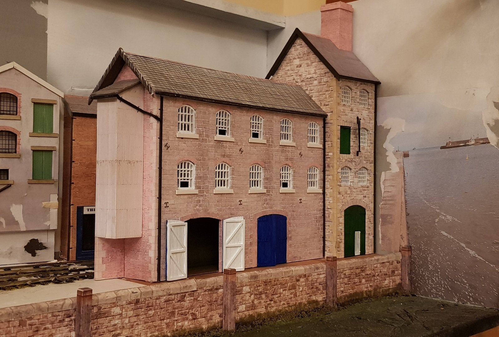
Over the break, I felt the layout could do with some upgrading. I was never really happy with the front buildings and the associated bridge - to me they were never very convincing. The flat look to the small grey building mid scene also could do with some change to the aspect to set it better in the scene. Some additional quay space would be useful to develop the scene and allow for some figures and cargo. So, some new buildings were designed around the materials used in the other buildings, slimmed down to provide this space. Windows and doors were printed on the 3D printer to add some depth with glue 'n' glaze used to provide glazing. A simple wall hoist was also printed to add some detail. Inserted into the main layout to give some context - considerable damage was done when removing the original buildings, but I plan to do some work with the surface as the printed cobbles were both poorly rendered & prone to peeling away. Perhaps some DAS clay & patterned roller? Just visible on the left of the final image is a view of the grey building with the stairs removed - this will need some redesign of the lower area, and then turned to reduce its "flatness", which will require some roof modifications. The buildings will need some weathering, but that can be done once the buildings are finally set in place. Anyway - all for now.
- 71 replies
-
- 17
-
-
-
-
1/32 Scale Mountfleet Round Table Minesweeper
KMCE replied to Georgeconna's topic in Aviation & Maritime Modelling
Nice work George. The drag created by the kite, otter & oropesa must have been considerable, slowing an already slow process. I assume the lengths of chain on the kite would help to create the correct offset from the ship by adjusting their lengths? Ken -
Looking good & coming together very quickly. Happy Christmas & looking forward to progress. Ken
-
Pray tell, why would you put said image up on the internet were this your inclination???
-
I wouldn't go quite as far as that. I seem to have found a balance between printer settings and resolution, however I am finding anything with serious curves is causing striations. I may look at adaptive layers to reduce the layer height on strong curves to improve the finish on the curved elements. I would be interested to hear what printer / settings you are using with angled prints. As mentioned before, I found angled prints were causing strange striations on the final print, however I am open to learning other solutions.. Ken
-
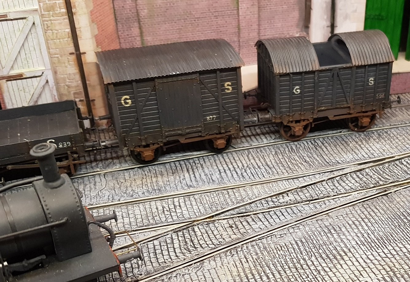
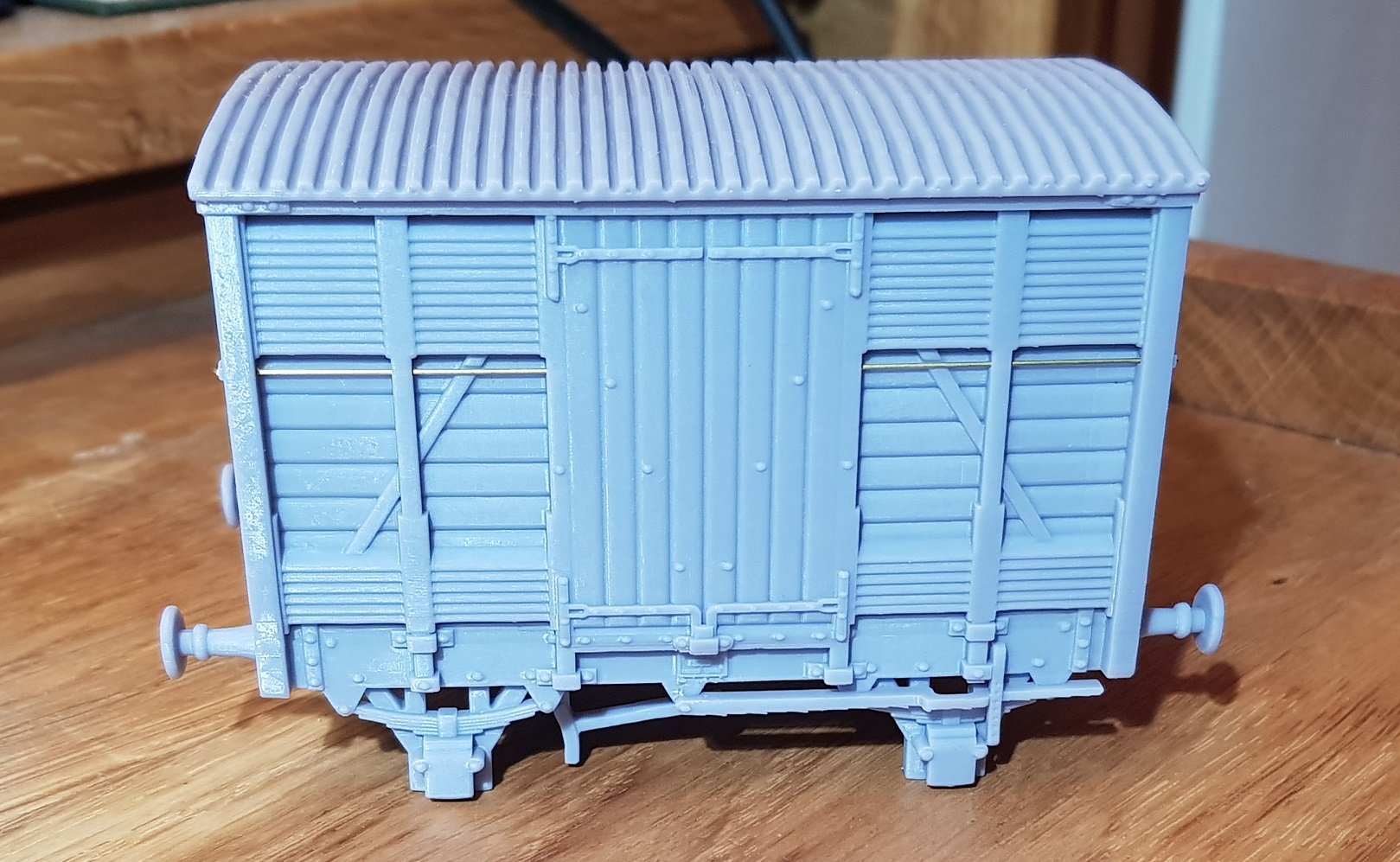
Very similar, but some minor differences - the sloping steel bracing is missing, roof is plain rather than corrugated, and door locking is external; perhaps a later re-built version? The DSER vans were long lived and were fitted with through piping to allow them run with coaching stock - it would not have been unusual to see one run as per the photo above. Ken
-
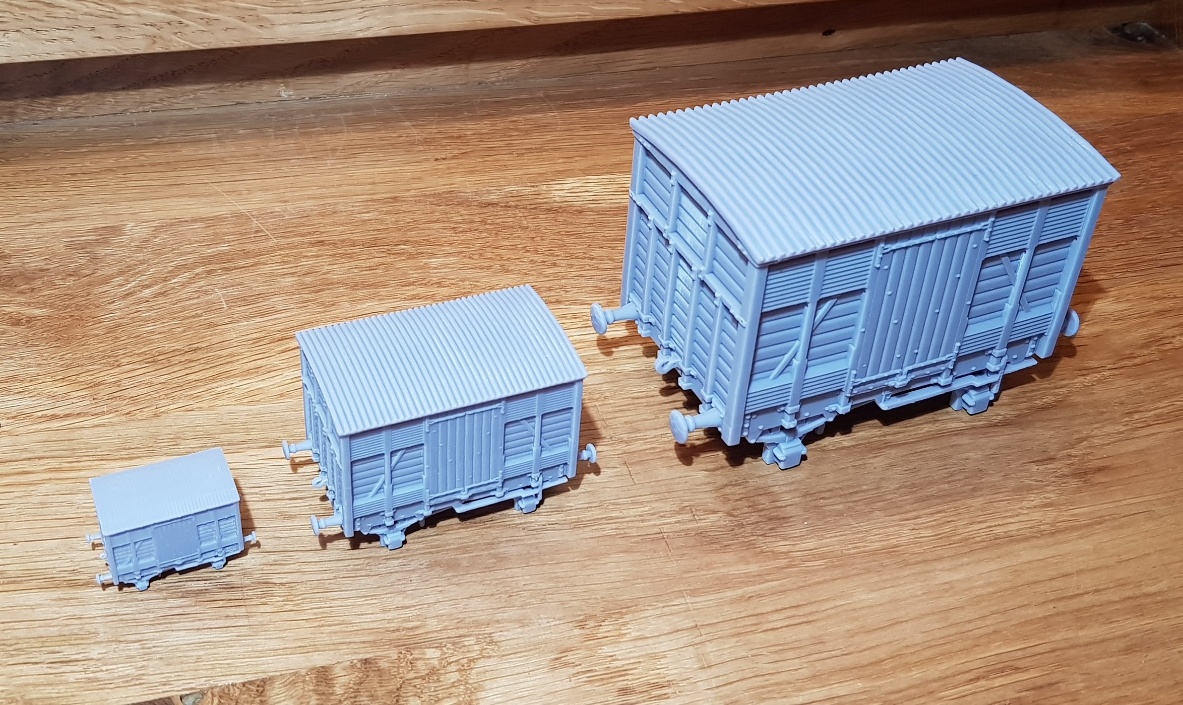
Matryoshka indeed. Alas, the wagons do not fit inside each other!!
-
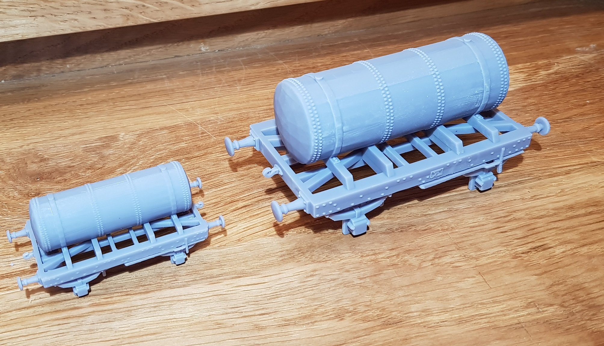
Gas Wagon in 4mm & 7mm. I think we are good to go!
-
2mm , 4mm , & 7mm versions:
-
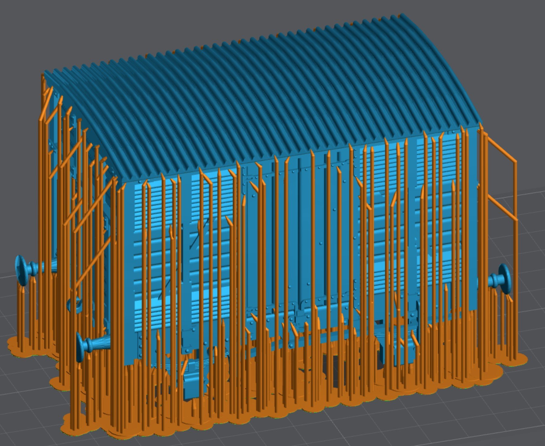
Agreed John. Your supports are very interesting and will considerably reduce risk of separation from the FEP, however I have found that keeping the model as close to upright as possible helps to reduce support marks on the visible surfaces & reduce the risk of angled striation across the sides of the model. I suppose it does depend on your exposure settings, I have found a slightly longer exposure gives a stronger model, albeit with the risk of striations. It does lead to a considerable support structure though!
-
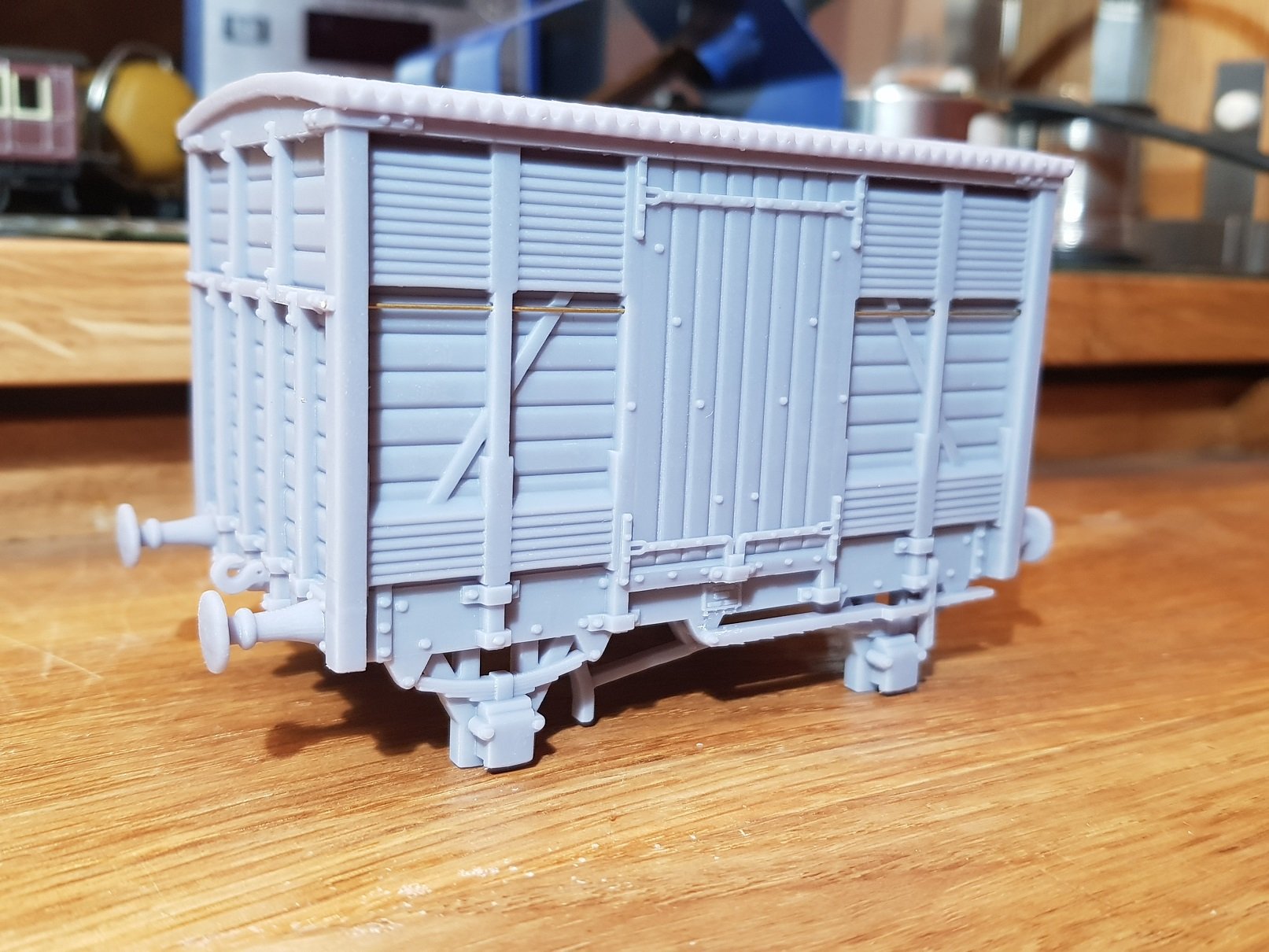
Quick update to this post to show how the 2mm and 7mm versions of this model printed: First up - 7mm And, its little brother....