David Holman
-
Posts
4,359 -
Joined
-
Last visited
-
Days Won
117
Content Type
Profiles
Forums
Events
Gallery
Blogs
Everything posted by David Holman
-
Interesting. Over many years and at least a dozen layouts, would say that a through layout needs more stock than a terminus to fiddle yard set up. The former needs more operators too - especially if there is a fiddle yard each end, rather than a continuous run where you can just let trains circulate. Fintonagh, my Clogher Valley layout, has just four trains and at shows, a sequence takes around 30-40 minutes to complete, depending on how much visitors want to talk to you. Incidentally, over 100+ shows, have found that, for me at least, there needs to be a balance between sequences that are interesting to operate, but not too complicated so that it becomes stressful. Overall therefore, half a dozen trains can be plenty to keep visitors amused, because the vast majority will only spend a few minutes in front of a layout. A couple of spare locos is always a good idea though, because at shows there is always a greater chance that things will go wrong. After all, not many folk operate trains at home for 6-8 hours on the bounce and that is another reason to avoid making operation too complex. Another factor with exhibiting is that the more stock you have, the longer it takes to set up before a show and likewise put everything away at the end. I can get Fintonagh set up in about 45 minutes and back in the car afterwards in half that. Then there's the issue of moving everything too and from the car/van/trailer, including when it might be raining, or worse. I could go on, but if you can get hold of any of Iain Rice's books like Cameo Layouts, he goes into detail about all the things to consider. Exhibiting is good fun, but it's not easy!
-
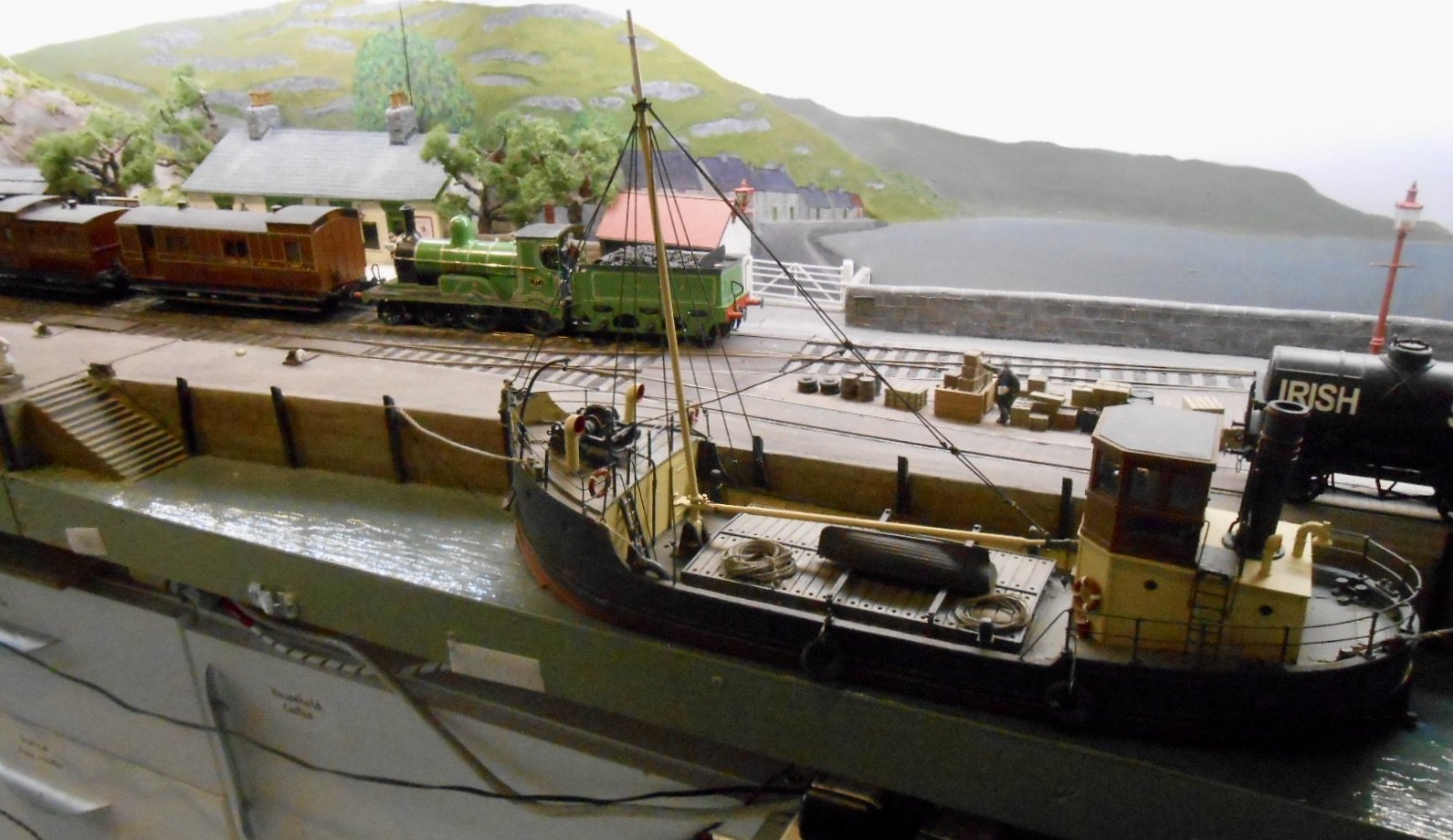
Given the site of the station, a fair bit of engineering would have been needed to make it into a through line. Would make an interesting model though! More than one person on this forum has pondered on the other line out of Sligo, namely the branch down to the quay. Have often thought it would have made a nice passenger line if extended up the coast a bit.
-
Looks ok to me.
-
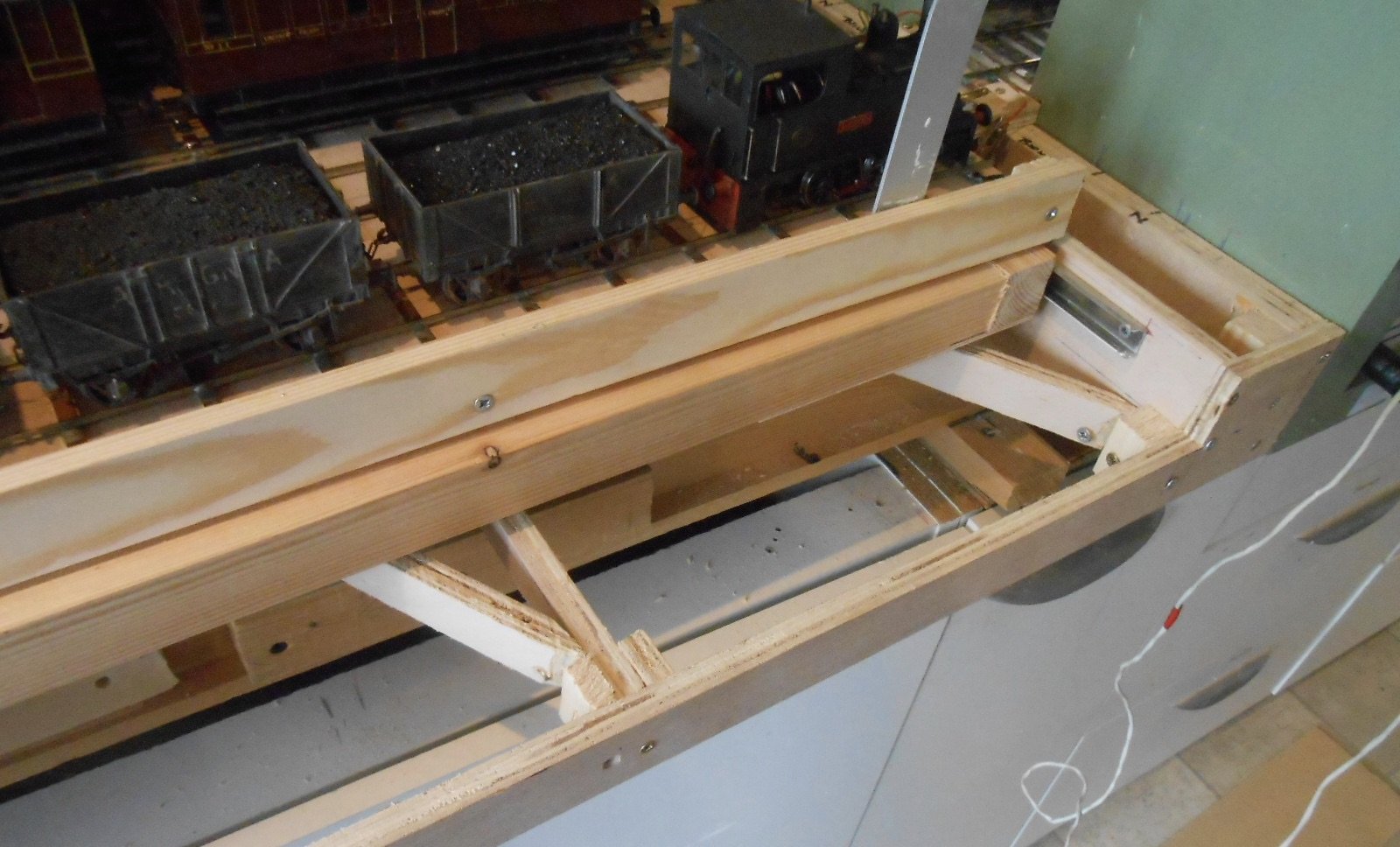
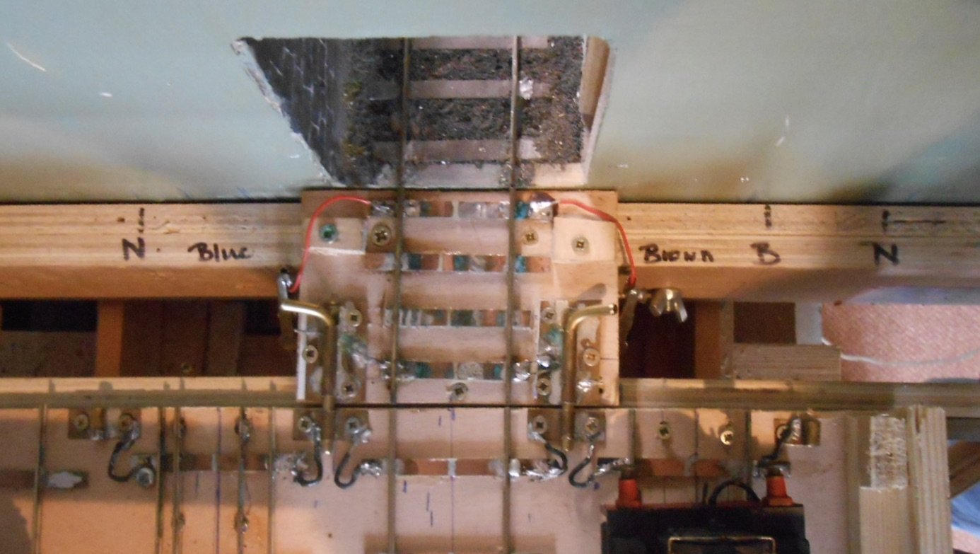
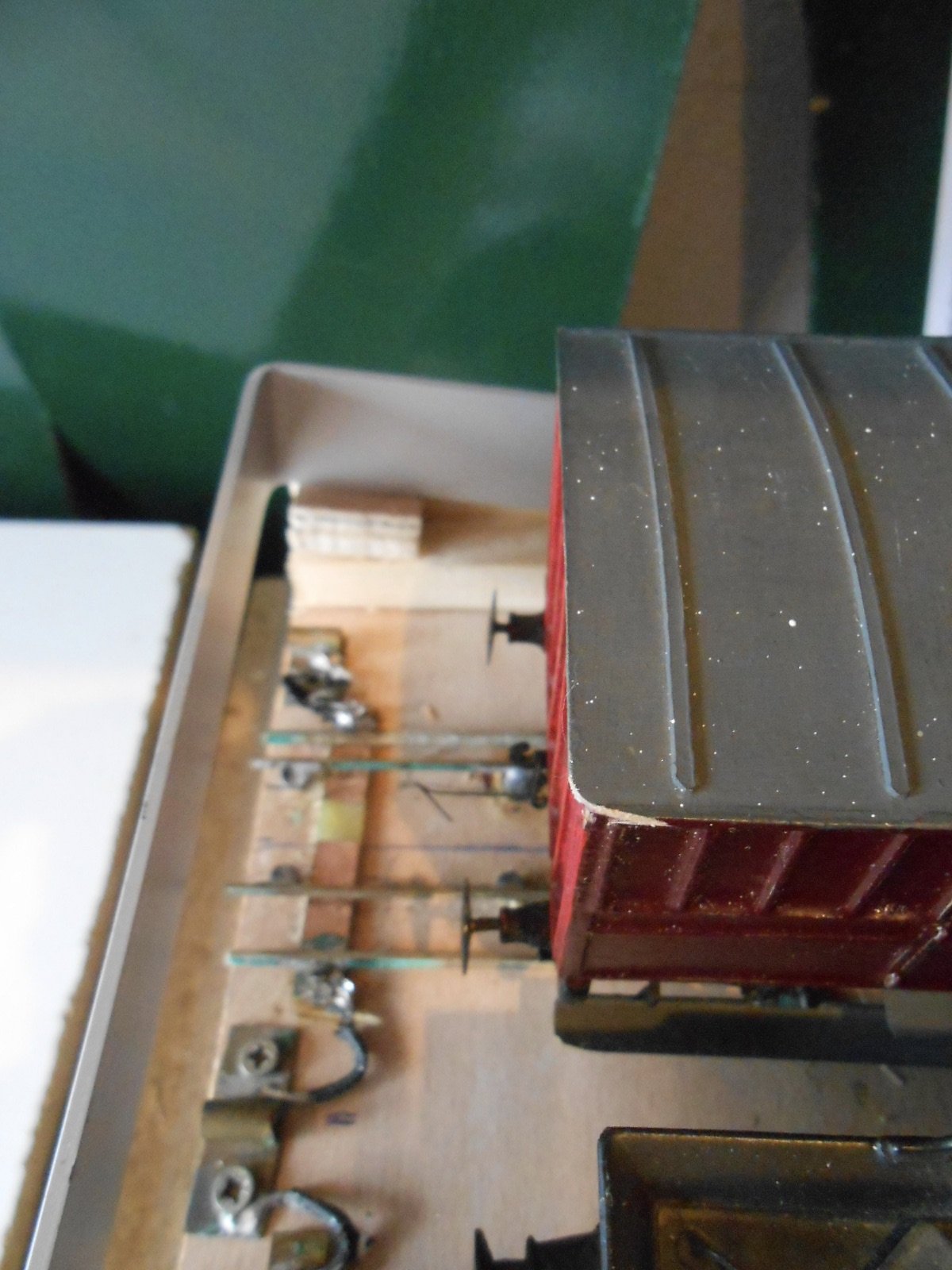
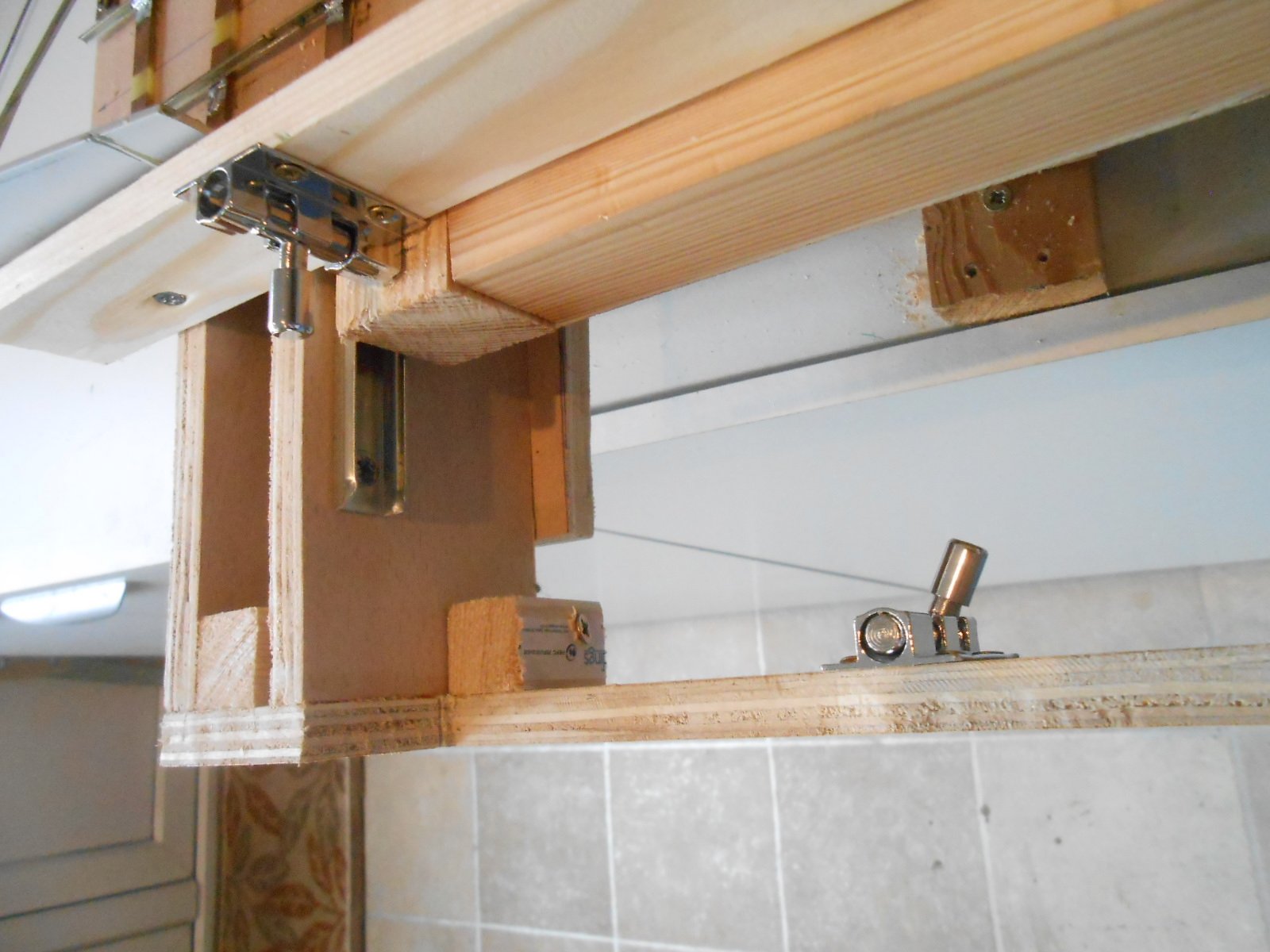
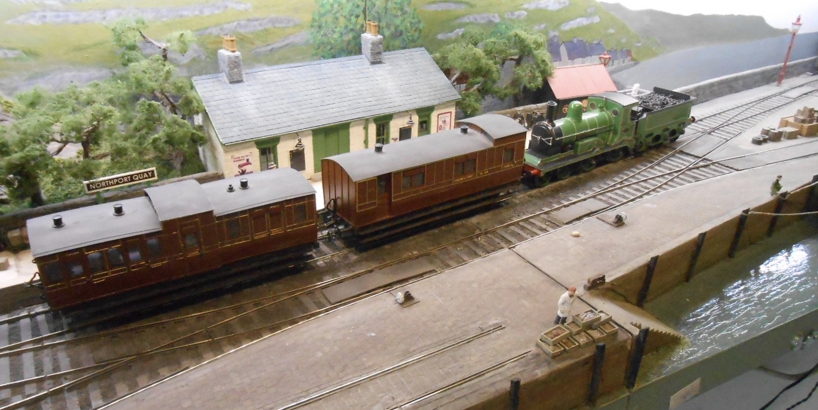
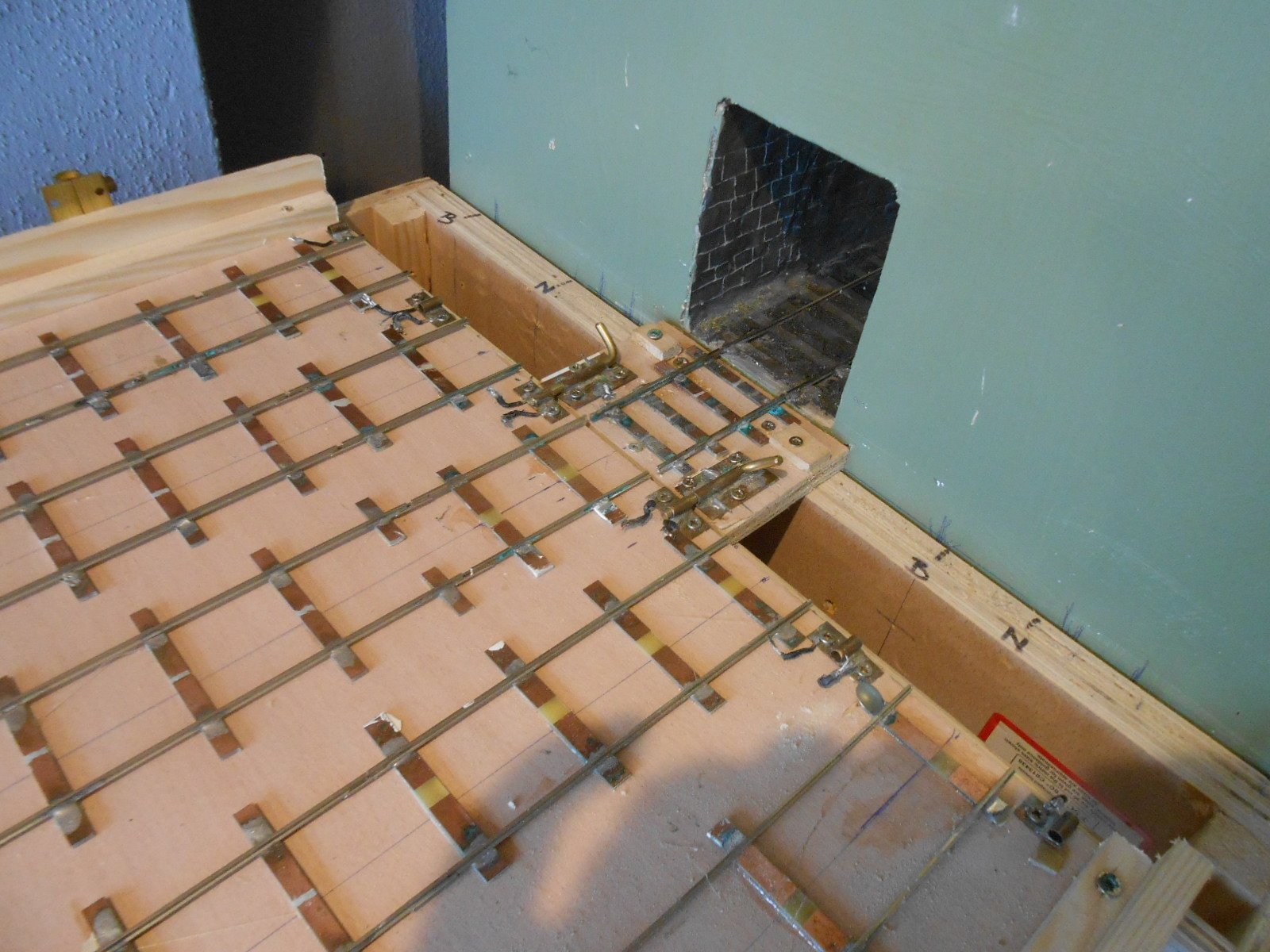
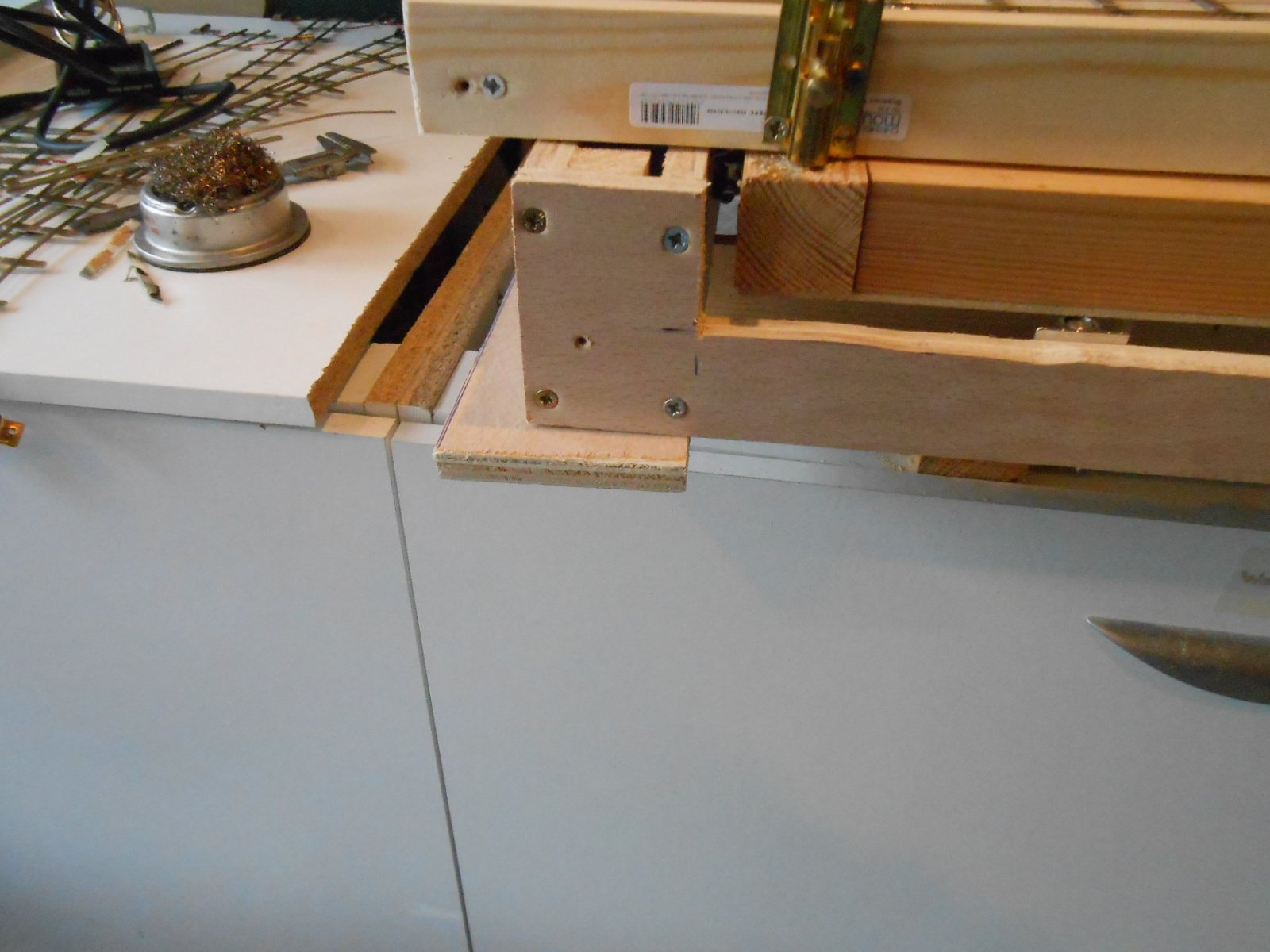
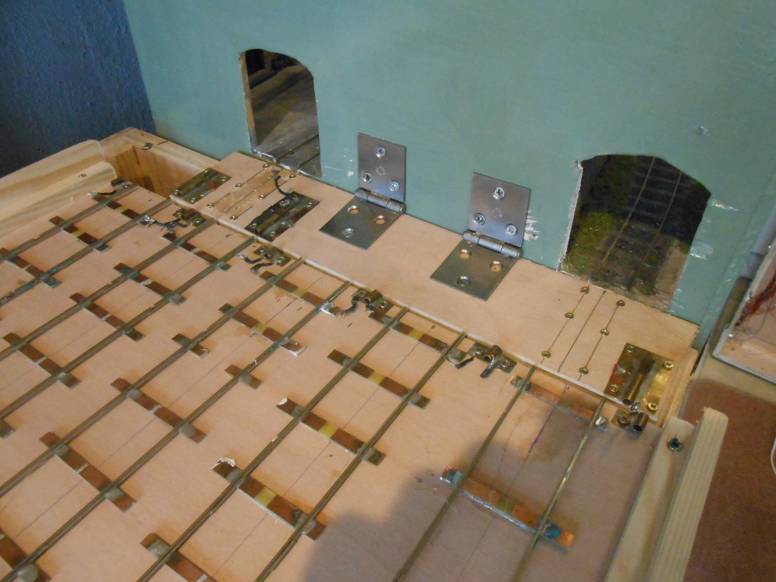
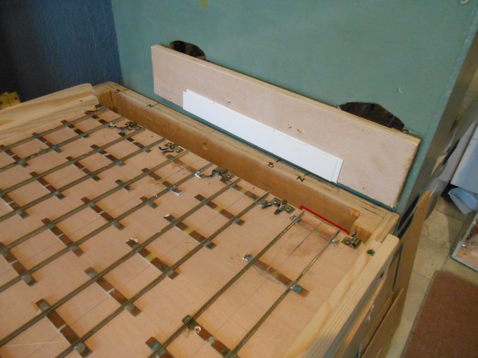
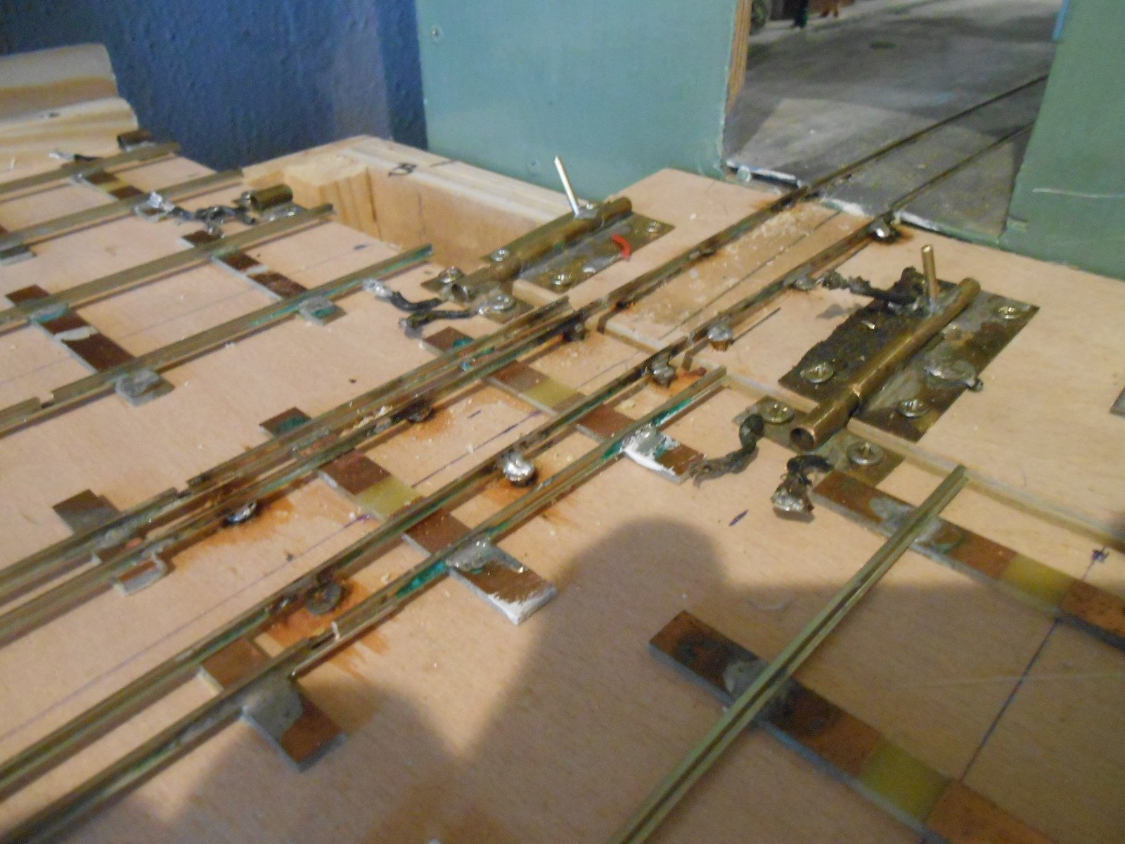
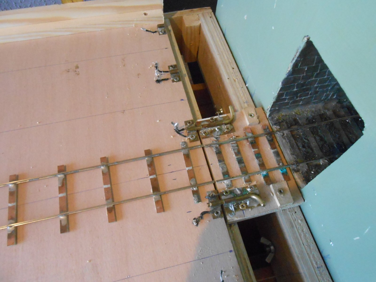
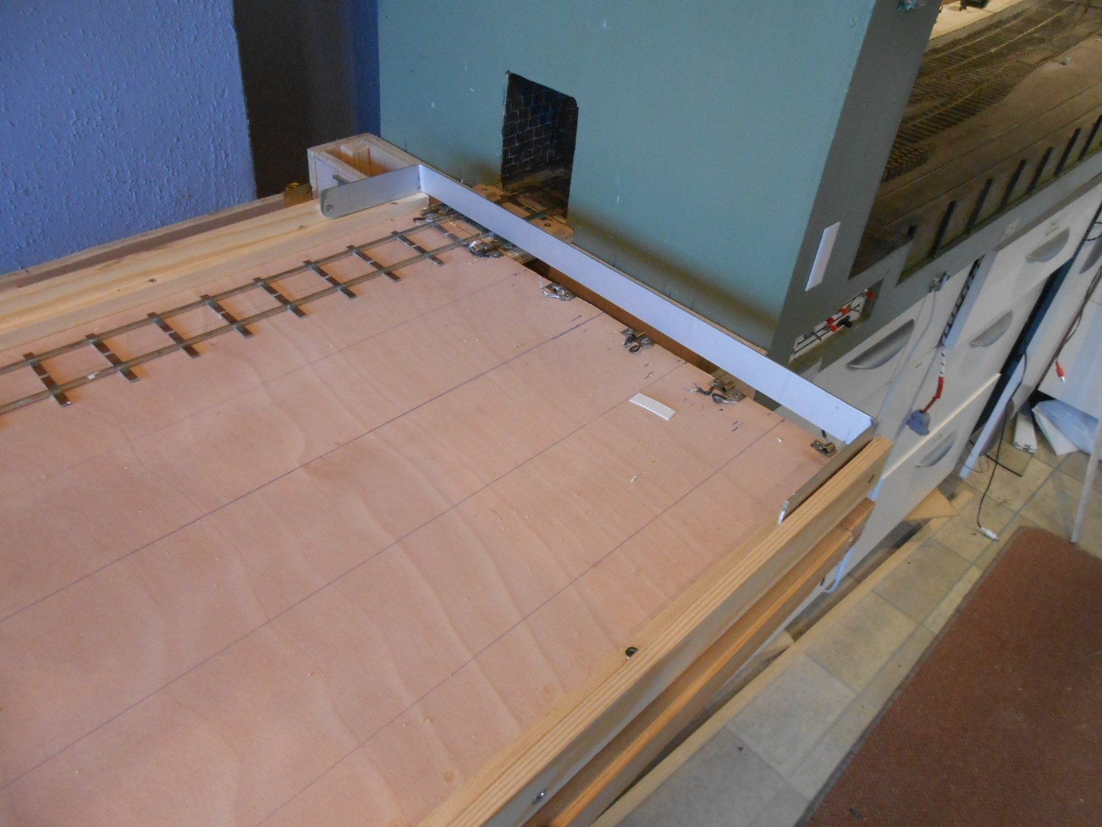
Finally got the new fiddle yard hooked up to NPQ today, enabling trains to be run for the first time in months! Just as well really, because the layout's next outing is the Chatham Show, at the end of July, which isn't that far away now. The main work was wiring in all the bolts - two wires from each one to the adjacent rails, meaning only one track is ever live. Power to the track comes from two wires from the layout, which each have a crocodile clip on them. These go on a screw each side of the short bridging track & a single wire from each screw goes to the rails, with another from the rails to each bolt. Safety next, with the hinged aluminium strip buffers at each end of the train table. Small blocks of plywood mean the buffers will clear the Alex Jackson couplings when lowered. The main frame of the fiddle yard was flexing a bit, so I cut some strips of 12mm ply and fitted these as diagonals between the intermediate frame pieces, which nicely triangulates things and adds some all important rigidity. Also replaced the oversized bolts, which ensure the table remains parallel to the frame when being slid from side to side. After that, it was time to put trains on the table and do a few test runs. Happily, all seems well, though care is of course needed when turning the table, once everything has been out & back - but then it was the same with the previous model. Some priming and painting now required, so everything matches the layout boards, plus I really must work out where to fit the all important coffee/tea cup holder.

- 257 replies
-
- 19
-

-

-
N Scale Ballywillan, Co Longford.
David Holman replied to Kevin Sweeney's topic in Irish Model Layouts
Fab. Well done! -
It was really sad to read of Ken's (KCME) passing today and looking back at some of his posts didn't make it any better. We have lost a rare and remarkable talent. Recently, we have also learned that Patrick's wonderful layout has run its last train and this has set me thinking. This Irish Railway Models Forum is a really valuable resource and hopefully Ken, Patrick and other's work will remain here, available to view for many years to come. However, as is the way of things, when individual posts no longer get updated, they eventually drop off the front page and fall down the order, not lost, but increasingly out of sight, so I have a proposal: Is it possible to set up a new category to cover such things? For example Ken didn't just have his work bench thread, he posted other topics too and wouldn't it be nice to put them all together under a single heading in a new category? Similarly, rather than just see Patrick's layout drop from the scene, would this also be a worthy move to preserve its interest? There must be other layouts that have similarly passed on, as it were. Another thought concerns esteemed modellers of the Irish scene, who have not been with us for quite a while - for example Drew Donaldson, Richard Chown, etc. While neither posted here, feel sure we could easily create an archive of their work. Technically, am thinking it would probably be down to the administrators to set up a new category and then find and migrate posts to appropriate sections - especially for folk no longer with us. An archive for old layouts could be cut and pasted by anyone still around, likewise any historical stuff. Seems like a decent idea to me, though there may be obstacles I haven't considered, but just wondered if there might be a way to honour the best of what we have here and Ken was certainly up there.
- 4 replies
-
- 10
-
-

-
Such sad news. Always interesting, innovative and just genuinely clever in his modelling. We are all richer for his contributions here and would have loved to meet him. RIP Ken.
-
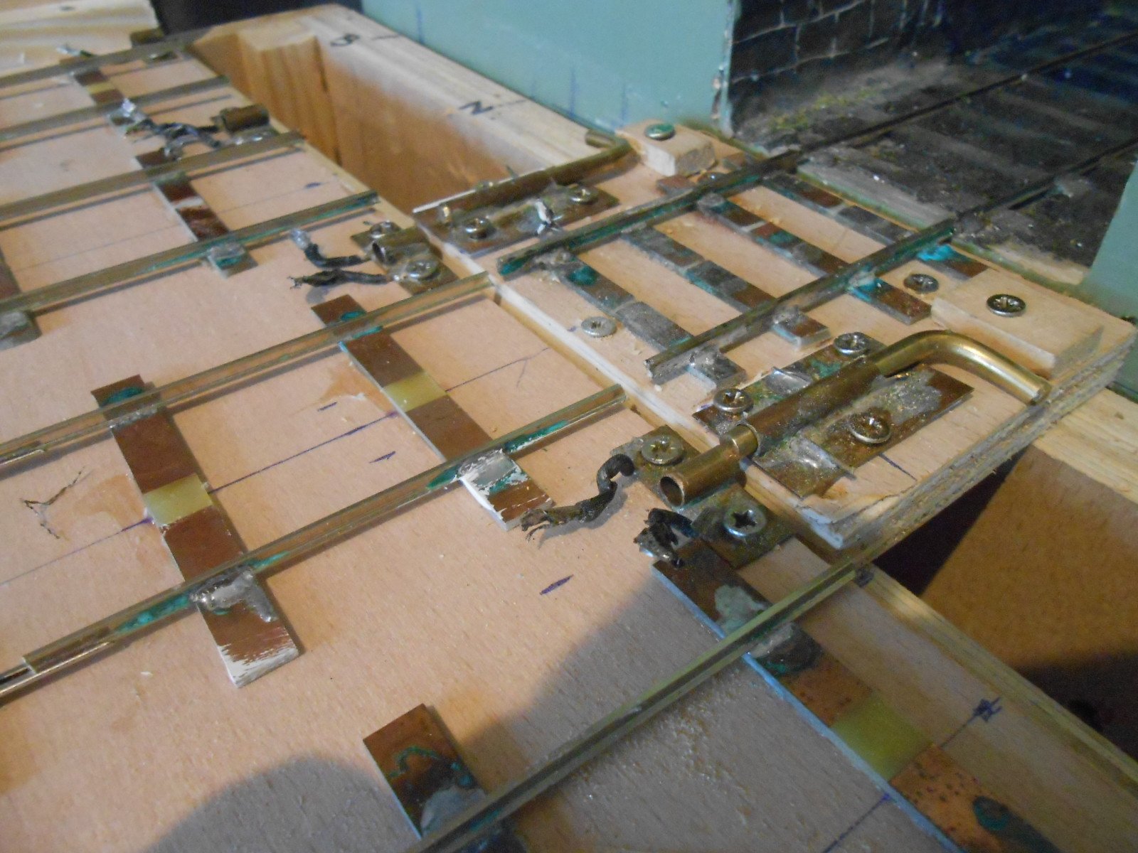
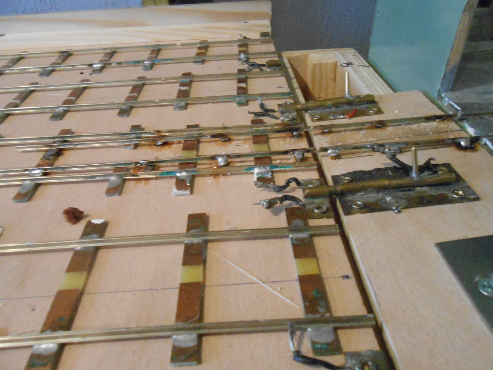
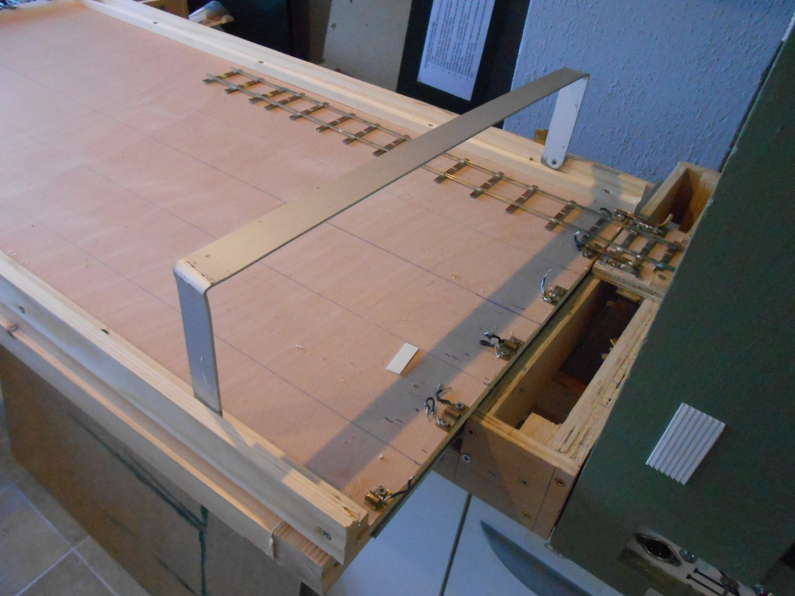
The fiddle yard's design has been, of necessity, somewhat organic - given it needs to serve two layouts, with different track exits. Getting track heights right at the two interfaces has been tricky. I used 12mm ply for the single, broad gauge track & [for once] careful measurement has meant that Code 100 rail and copper clad sleepers line up nicely with Northport Quay. The home made bolts line up the track table, though the ones on the 'bridge' have needed to be raised by one millimetre - not really surprising given that the track table uses 9mm ply. Another built in complication is that Fintonagh's boards are one centimetre deeper than NPQ's, so the fiddle yard requires a piece of plywood at the far end to level it up. However, fingers crossed, laying the track seems to have everything lining up nicely &, if necessary, the copper clad sleepers mean the rails can easily be adjusted. For Fintonagh, decided I needed a completely different interface, so when this layout goes to shows, the NPQ one will be unscrewed. After much thought, decided to make Fintonagh's hinged from the layout baseboard and wide enough to cover both layout exits. However, the different baseboard height, along with the fact it uses Code 83 rail, has meant a degree of jiggery pokery has been required. The exit from the layout is 3mm higher than the track table, so rather than use copper clad sleepers on the bridging section, I've used small screws and soldered the rail to these. Have also used screws for the first 15cm or so of the track table, before the rail eventually gets soldered to the broad gauge sleepers. This reduces the gradient between the two to about 1 in 75, compared to 1 in 25, though am yet to find out if this works or not. Have managed to salvage quite a bit of Code 83 from Fintonagh's turntable fiddle yard, but not enough for all of the new one. At least I'll be able to test it, once the wiring is completed, while another, unplanned, test occurred this afternoon when the new fiddle yard fell of the work bench onto the workshop floor. It seems ok, though not sure how the floor would have got on if it had been the old version!
-
Fantastic work, Roger.
-
Beagnach end: A Branchline terminus.
David Holman replied to Metrovik's topic in Irish Model Layouts
Back in the day, I believe it was common practice for an unfitted goods train to stop outside loop of a terminus station to ensure it was under control and minimise the possibility of a runaway smashing into the buffers. Not something I see done very often at exhibitions, but worth including for that extra bit of authenticity perhaps? -
Wonderful stuff! Many thanks, Roger.
-
And even then, compromises with the driving wheel spacing are required. On the prototype, they were almost touching!
-
Thanks Patrick - stunning to see the layout in its entirety.. As for those buildings, just exquisite.
-
Still need nearly twelve feet to model that...
-
12 years and over 450,000 views! Quite a ride, Patrick. Hope the moves go well and that it won't be too long before you start posting about a new project
-
Nice! Believe there is one due out in 7mm scale, so will be very interested to see if the wheels can be moved out to broad gauge.
-
Necessary evils, both!
-
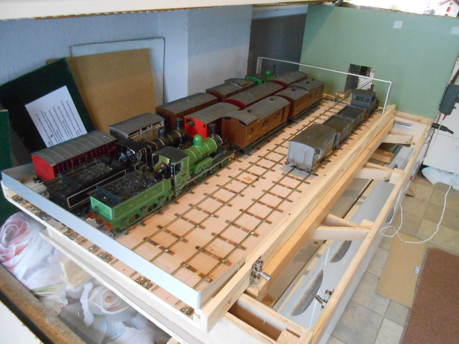
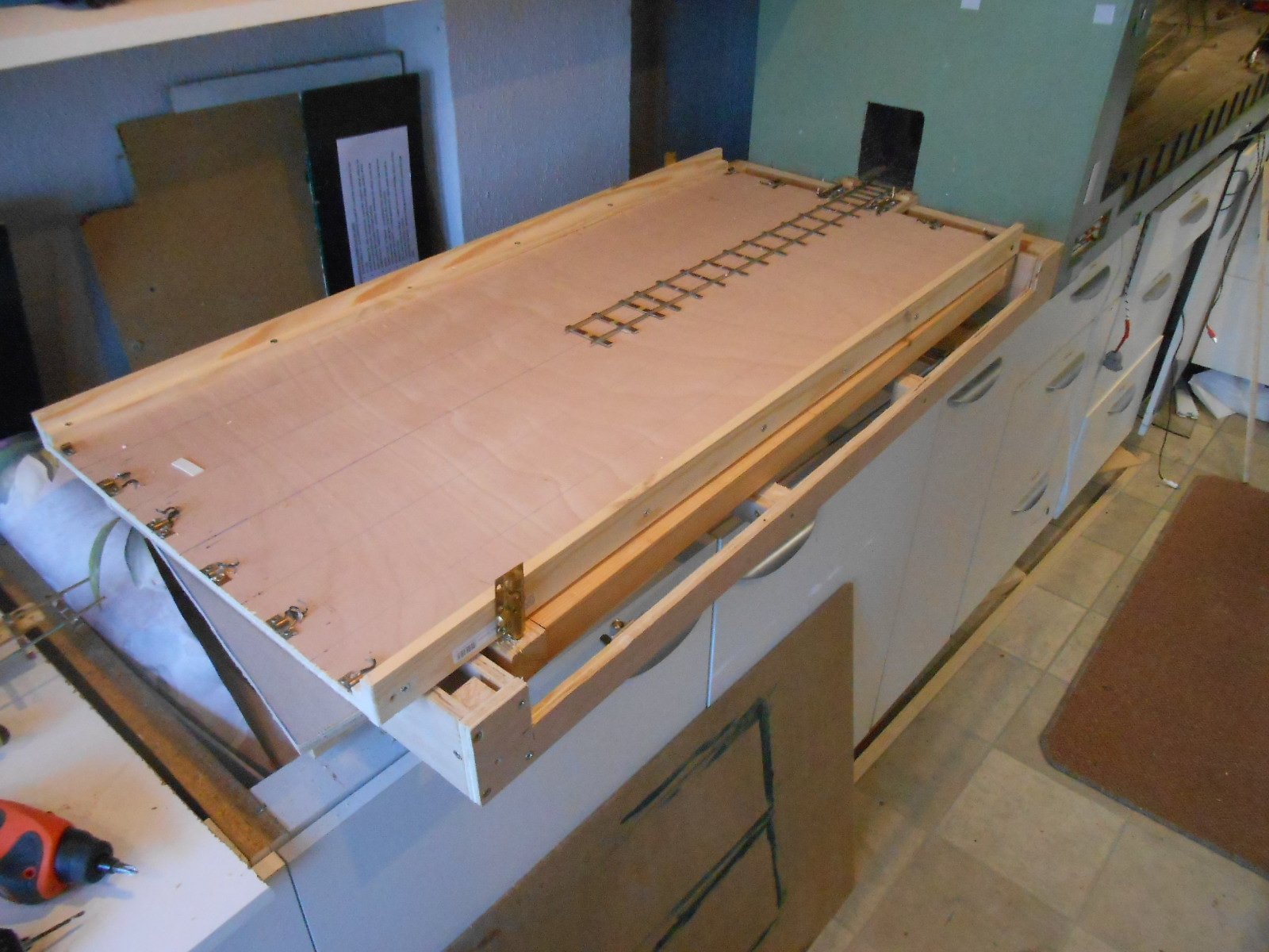
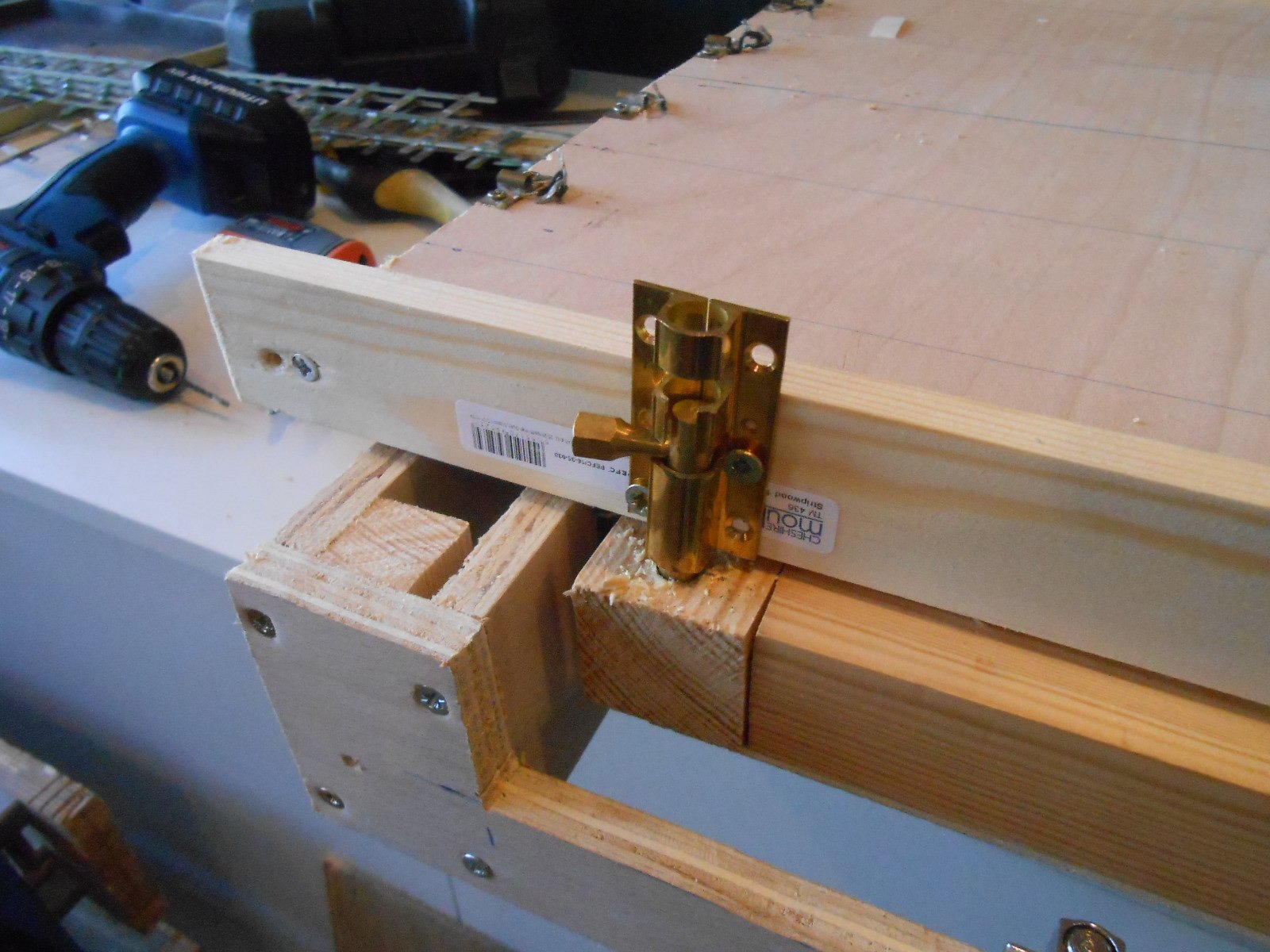
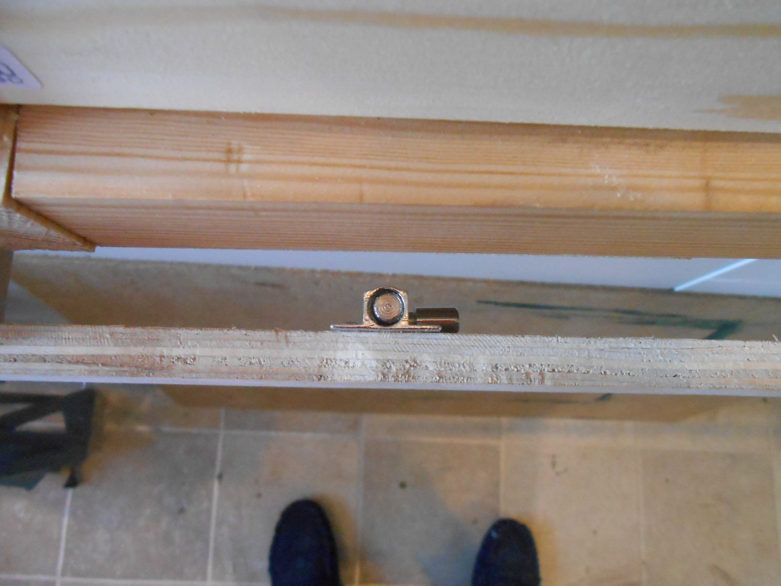
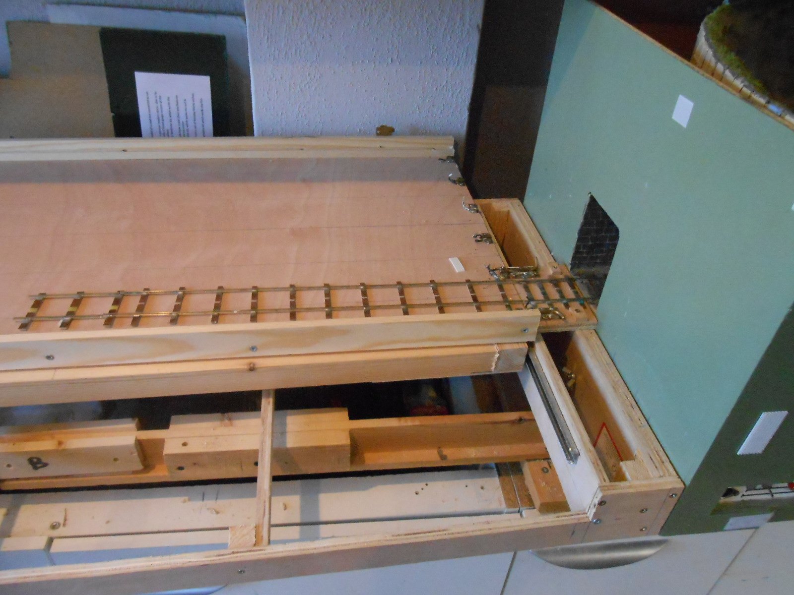
New Sliding & Rotating Fiddle Yard Having been repeatedly stymied by having to send off for materials on current projects have finally managed to get on with something for a change, though even here, it was not without its problems! The original Arigna Town fiddle yard has earned its keep over the years. Based on a design by the late Robin Fielding back in MRJ 199, it proved ideal in meaning entire trains could be turned without the need for any handling - a real boon at exhibitions and still a talking point too. The only downside was that it was very heavy. I cut it down quite a bit to use with Northport Quay, making it both shorter and narrower, but it still weighed too much. I also wanted a fiddle yard that would work with Fintonagh in its Swilly/Donegal reimagining, so a brand new version was the only answer. There are three main parts to a fiddle yard like this: the frame, the sliding table and then the rotating track table. I made the frame from 12mm plywood. The ends are 90mm deep and 500mm wide. The sides are a long U shape [1000mm], with the cut away section accommodating the sliding table. The latter sits on two way drawer runners, which are screwed to more 12mm ply. Just like last time, I somehow got one way runners at first, which don't work at all and had to send off for replacements. Note to self - read the Amazon description more carefully in future! Everything needs to be as square as possible, so I used 25mm square softwood to reinforce the corners, with a couple of cross braces and everything screwed and glued together. The sliding table bit was built in situ. I fixed the drawer runners to two pieces of 31mm square softwood, which form the ends of the table and then fixed these to each inner ends of the main frame. Two longer pieces of 31mm wood were cut to make the sides and these were aligned and held in place with rectangles of 3mm ply across the underside of each end. Like the main frame, the sliding table is completely open, to save weight, though it also has a couple of cross braces on which sits a Lazy Susan [10cm cake turntable]. The height of this needed to be measured very carefully, so that, once fitted, the track table would exactly match up with the track leading from the layout. On the original model, the track table was a pieces of 12mm MDF - again, very heavy. This time I've used 9mm plywood, braced with 12mm and 40 x 12mm softwood along each edge. Several additional items are needed: A piece of 12mm plywood forms the link to the layout. This has a piece of 36.75mm track on it, together with two home made bolts [brass rod, tube and plate] which both align with each of the five tracks on the table and carry power from the layout itself. A separate piece of 12mm ply will used to carry the two 21mm gauge tracks from Fintonagh. These are on a different alignment so the two must be interchangeable. The alignment sections for the bolts on the track table are similarly home made. When the track is fitted, Code 83 rails [21mm gauge] will be soldered in between the broad gauge, Code 100 rails, thereby enabling the new fiddle yard to work with both layouts. A spring connector will be fitted underneath the main frame to take the two track wires from the main layout. All fiddle yard tracks are isolated, unless connected via the alignment bolts A hinged barrier [aluminium strip] will be fitted each end to stop stock running off the ends A small bolt underneath is used to secure the sliding table for transport Two further small bolts [currently oversize in the pictures] are used to lock the track table in place when it is in sliding mode. Sliding the table from side to side enables all trains to enter/exit the layout. When they have all returned, the bolts are undone and the train table is pulled out beyond the entry track and then turned so that everything is ready to go out again. Hopefully, the pictures below will help make sense of the above. There is a fair bit of finishing off to do, not least laying the track, but it all works very smoothly and weighs far less than the original version, which has to be a very good thing. Though quite complicated to make, to me, this is by far the best type of fiddle yard I've used and this includes points, cassettes and full turntables.
-
Indeed! Have even found putting the offending article on a shelf/back in its box for a while only to return to it a few days later to find all is not as bad as it seems. In the meantime, do something nicer, as per this morning when I visited a local wild flower meadow to be in awe of thousands of wild orchids. Rule Number 1 - always stop while you are winning Rule Number 2 - NEVER think you can just do one more thing - it will always bite you later
-
Hand built track shouldn't be a problem, but, from my experience it certainly can be. Experts can argue that using gauges properly minimises the variables - and I guess it should, but somehow there always seems to be a lot of fettling required. I put it down to the fact that I only build track every few years and it means I just lose the knack - that's my excuse, anyway! Stock building occurs more regularly, so less of a problem - though the saga of my Barclay 4-6-0T rumbles on. Basically, anything that moves (and include electrics in that), will try to bite you! Life is complicated, which is why it is fun. Most of the time, anyway.
-
How do the uncouplers work? Presume they are tiny rare earth magnets, but are they just manual, as per three links? Am guessing the video tells all, but the site says it can't be found.
-
Sometimes, it can be nice to take time out and indulge in your creations - especially when they are as fine as this. Love the subtle co!ours.
-
7mm scale, broad gauge wagons? Tell us more.
-
The Ellis Clarke 7mm scale one is getting positive reviews - a bag of sand should get you one if you have the means...
-
As ever, well worth the wait!